


KP-53SV75C
Table of contents
 Loading...
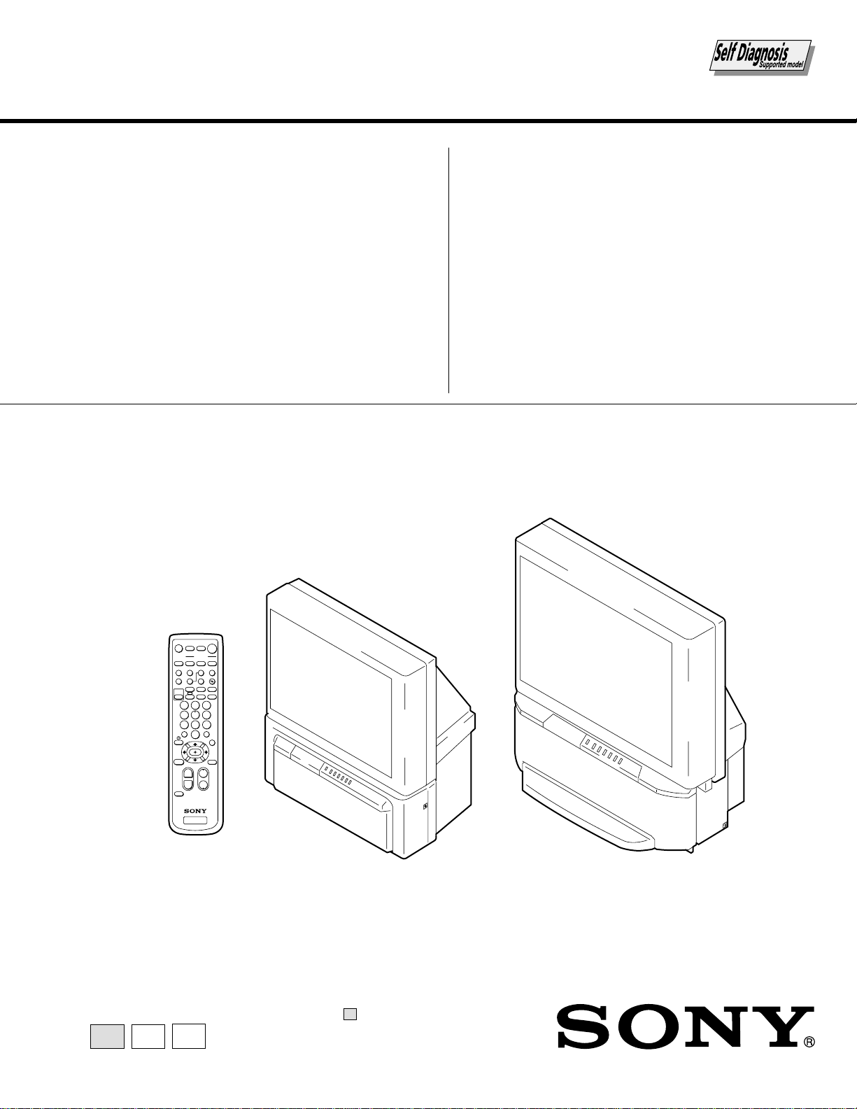
CHASSIS
SERVICE MANUAL
MODEL COMMANDER DEST. CHASSIS NO.
–––––– –––––––––––– ––––– –––––––––––
MODEL COMMANDER DEST. CHASSIS NO.
–––––– –––––––––––– ––––– –––––––––––
∗ Please file according to model size. .......
RA-3A
KP-43T75C RM-Y906 Chileean SCC-P52B-A
KP-43T75C RM-Y906 Peru SCC-P52B-A
KP-53SV75C RM-Y906 Chileean SCC-P52C-A
KP-53SV75C RM-Y906 Peru SCC-P52C-A
KP-61SV75C RM-Y906 Chileean SCC-P52A-A
KP-61SV75C RM-Y906 Peru SCC-P52A-A
43
COLOR REAR VIDEO PROJECTOR
53
KP-43T75C KP-53SV75C/61SV75C
RM-Y906
TV
2
5
8
0
1
4
7
3
6
9
ENTER
JUMP
GUIDE
INDEX
RESET
MENU
CODE SET
VOL CH
POWER
MUTING
FREEZE
AUDIO
ANT
TV/VIDEO
DISPLAYMTS/SAP
CC
PICTURE
MODE
POSITION ACTIVE
SWAP PIP
TV/VTR
SYSTEM
OFF
DVD/VTR SAT/CABLE
TV
DVD/
VTR
SAT/
CABLE
FUNCTION
SLEEP
m
N
M
xz
X
TV
61

– 2 –
KP-43T75C/53SV75C/61SV75C
RM-Y906RM-Y906
RM-Y906
SPECIFICATIONS
Projection system
3 picture tubes, 3 lenses, horizontal in-line system
Picture tube
7-inch high-brightness monochrome tubes (6.3 raster size),
with optical coupling and liquid cooling system
Projection lenses
High performance, large diameter hybrid lens F1.05
Television system
NTSC
Channel coverage
VHF: 2–13/UHF: 14 –69/CATV: 1 – 125
Antenna
75 ohm external terminal for VHF/UHF
Screen size (measured diagonally)
43 inches (KP-43T75C)
53 inches (KP-53SV75C)
61 inches (KP-61SV75C)
Inputs/outputs
VIDEO 1 IN
VIDEO 2 INPUT
S VIDEO IN (4-pin mini DIN):
Y: 1 Vp-p, 75-ohms unbalanced, sync negative
C: 0.286 Vp-p (Burst signal), 75 ohms
VIDEO (phono jack): 1 Vp-p, 75-ohms unbalanced,
sync negative
AUDIO (phono jacks): 500 mVrms (100% modulation),
Impedance: 47 kilohms
VIDEO 3 IN
S VIDEO IN (4-pin mini DIN):
Y: 1 Vp-p, 75-ohms unbalanced, sync negative
C: 0.286 Vp-p (Burst signal), 75 ohms
VIDEO (phono jack): 1 Vp-p, 75-ohms unbalanced,
sync negative
Y: 1 Vp-p, 75 ohms, sync negative
P
B: 0.7 Vp-p, 75 ohms
P
R: 0.7 Vp-p, 75 ohms
AUDIO (phono jacks): 500 mVrms (100% modulation),
Impedance: 47 kilohms
MONITOR OUT
VIDEO (phono jack): 1 Vp-p, 75-ohms unbalanced,
sync negative
AUDIO (phono jacks): 500 mVrms (100% modulation),
Impedance: 470 ohms
AUDIO (VAR/FIX) OUT (phono jacks): 500 mVrms
(100% modulation), Impedance: 470 ohms
CONTROL S OUT: minijack
Speaker
66 mm (2
5
/8”) × 2, 160 mm (6
3
/8”) × 2 (KP-53SV75C/
61SV75C)
100 mm (4”) × 2 (KP-43T75C)
Speaker output
17W × 2
Power requirement
110-220 V AC, 50/60 Hz
Power consumption
In use (Max.): 160 W
In standby: 1 W
Dimensions (W/H/D)
965 × 1,058 × 510 mm (38 × 41
5
/8 × 20
1
/8 inches)
(KP-43T75C)
1,216 × 1,417 × 632 mm (47
7
/8 × 55
3
/4 × 24
7
/8 inches)
(KP-53SV75C)
1,370 × 1,560 × 670 mm (54 × 61
3
/8 × 26
3
/8 inches)
(KP-61SV75C)
Mass
65 kg (143 lbs 5 oz) (KP-43T75C)
77 kg (169 lbs 12 oz) (KP-53SV75C)
94 kg (207 lbs 4 oz) (KP-61SV75C)
Supplied accessories
Remote control RM-Y906 (1)
Batteries (2) size AA (R6)
Optional accessories
Connecting cables
RK-G34, RK-74A, RK-G69HG, VMC-10HG,
VMC-720M, VMC-810S/820S, YC-15V/30V
U/V mixer EAC-66
Design and specifications are subject to change without notice.
– 3 –
KP-43T75C/53SV75C/61SV75C
RM-Y906RM-Y906RM-Y906
SELF DIAGNOSIS FUNCTION
* : 000 the range of values for number of operations is 000-255. For 256 or higher there is
no count up and the number remains at 255.
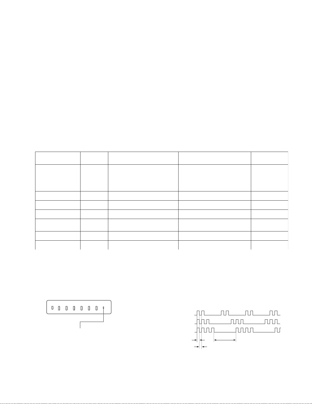
3. Blinking count display of TIMER/STANDBY indicator
< FRONT PANEL >
TIMER/STANDBY indicator
Lamp OFF :
3.0 seconds
Lamp ON : 0.3 seconds
Lamp OFF : 0.3 seconds
Release of TIMER/STANDBY indicator blinking.
• The TIMER/STANDBY indicator blinking display is released by turning OFF the power switch
on the TV main unit or removing the plug from the power.
* One blink is not used for self-diagnosis.
•EXAMPLE
<Diagnosis Items> <Number of Blinks>
• +B overcurrent 2 times
• +B overvoltage 3 times
• Vertical deflection stop 4 times
TV/VIDEO
FLASH FOCUS
VOLUME
POWER
TIMER/STAND BY
–+CHANNEL–+
1. Summary of Self-Diagnosis Function
• This device includes a self-diagnosis function.
• In case of abnormalities, the TIMER/STANDBY indicator automatically blinks. It is possible to predict the abnormality location
by the number of blinks. The Instruction Manual describes blinking of the TIMER/STANDBY indicator.
• If the symptom is not reproduced sometimes in case of a malfunction, there is recording of whether a malfunction was generated
or not. Operate the remote command to confirm the matter on the screen and to predict the location of the abnormality.
2. Diagnosis Items and Prediction of Malfunction Location
• When a malfunction occurs the TIMER/STANDBY indicator only blinks for one of the following diagnosis items. In case of two
or more malfunctions, the item which first occurred blinks. If the malfunctions occurred simultaneously, the item with the lower
blink count blinks first.
• The screen display displays the results regarding all the diagnosis items listed below. The display “ 0 ” means that no malfunc-
tions occurred.
metisisongaiD
YBDNATS/REMIT
retacidnI
sknilbforebmuN
noitcnuflamdesoppuSnoitidnoC
sisongaid-fleS
,yalpsidneercs
stluseR:metisisongaiD
NOtonrewoP•0
]metsySylppuSrewoPybdnatS[
.nepo106F
.nepo706R
tiucrictrohs106Q
]metsySylppuSrewoPniaM[
.nekorbera216Rdna106CI
tiucric-trohs106RDV
.rewopehtnonruttonnaC
.knilbt'nseodDEL
noitcetedPCOB+semit2.tiucrichcaenimetsysylppusrewopfotiucrictrohS
edomybdnatsehtotseoG
enilB+fotiucrictrohS
000PCOB+:2
noitcetedPVOB+semit3
.nepo87nip306T
.nepo276R
edomybdnatsehtotseoG
tiucricylppusrewopfonoitcnuflaM
000PVOB+:3
potsnoitcelfedlacitreVsemit4
.nekorbsi)tuoV(9051CI
.nekorbsi)reffuBesluPV(5051Q
oedivnehtdnaA,yllatnozirohenilenootseogretsaR
.detumsilangis
000potSV:4
noitcetedytilamronbatuooediVsemit5
draobCnisrehtodna167,237,507Q,tuooediV
.tiucric
)draobA(022,912,812Q
,sdnoces03.xorppasknilbDELYBDNATS/REMIT
.sisongaidflesehtrofsknilbnehtdna
000BKA:5
potsnoitcelfedlatnoziroHsemit6
.nepo615,515C
.nekorbsi)elgnuJCY(602CI
.raeppat'nseodretsaR000potSH:6
noitcetedytilamronbaoiduAsemit8
.nekorbsi).pmaoiduA(604CI
.nepo204,104SP
.tuotonsidnuosehT
edomybdnatsehtotseoG
000oiduA:8
– 4 –
KP-43T75C/53SV75C/61SV75C
RM-Y906RM-Y906
RM-Y906
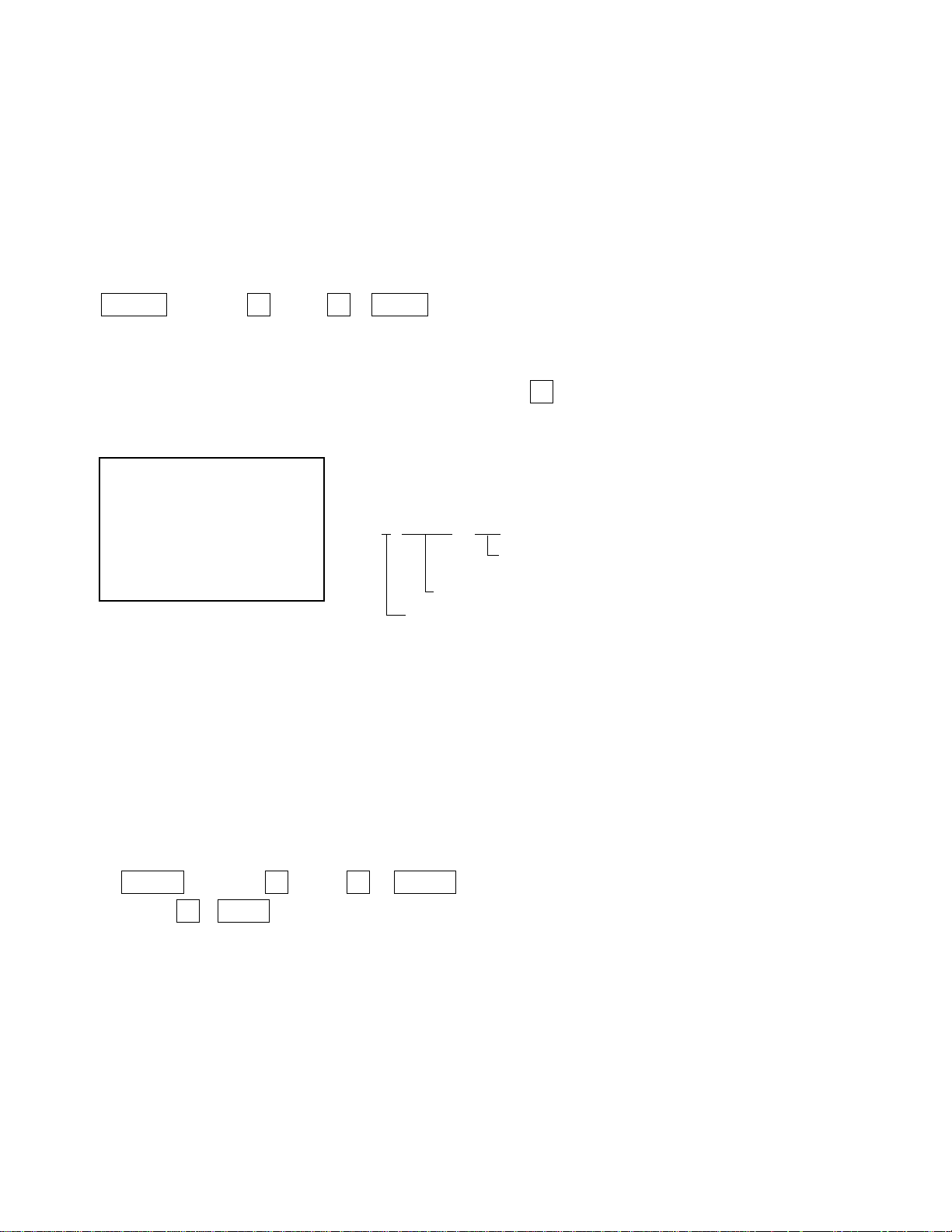
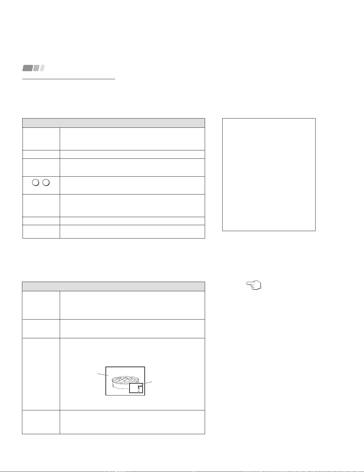
4. Self-diagnosis screen displays
• In cases of malfunctions where it is not possible to determine the symptom such as when the power goes off occasionally or when
the screen disappears occasionally, there is a screen display on whether the malfunction occurred or not in the past (and whether
the detection circuit operated or not) in order to allow confirmation.
<Screen Display Method>
• Quickly press the remote command button in the following order from the standby state.
Self Check
2 : +B OCP 000
2 : +B OCP 000
3 : +B OVP 000
4 : V Stop 000
5 : AKB 000
6 : H Stop 000
7 : HV 000
8 : Audio 000
101 : WDT 000
000 the range of values for number of
operations is 000-255.
For 256 or higher there is no count up
and the number remains at 255.
Diagnosis
Results
÷
Self-diagnosis screen display
5. Self-Diagnosis Screen Display
• The results display is not automatically cleared. In case of repairs and after repairs, check the self-diagnosis screen and be sure
to return the results display to “ 0 ”.
• If the results display is not returned to “ 0 ” it will not be possible to judge a new malfunction after completing repairs.
<Method of Clearing Results Display>
<Method of Ending Self Diagnosis Screen>
• When ending the self-diagnosis screen completely, turn the power switch OFF on the remote commander or the main unit.
˘
Be aware that this differs from the method of
entering the service mode (volume + ).
DISPLAY b Channel 5 b VOL – b POWER
1. Power off (Set to the standby mode)
2. DISPLAY b Channel 5 b VOL + b POWER (Service Mode)
3. Channel 8 b ENTER (Test reset = Factory preset condition)
– 5 –
KP-43T75C/53SV75C/61SV75C
RM-Y906RM-Y906RM-Y906
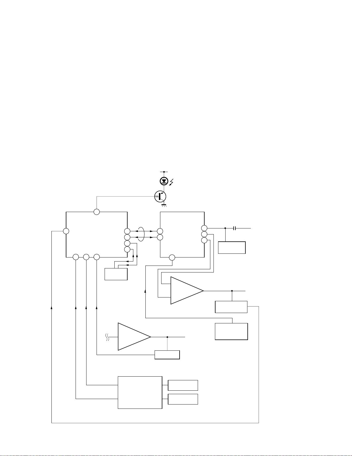
6. Self-diagnosis function operation
OCP Low B and +B line detect DET SHORT, and shut-down POWER ON RELAY.
Reset by turning power on/off.
In case of +B is loaded approx. 1.3A or more, microcomputer detects it via IC651.
OVP In case of +B becomes approx. 150V or more, POWER ON RELAY shuts down and microcomputer detects it via IC651.
Reset by turning power on/off just the same as OCP.
V Stop In case of microcomputer detects 2 seconds or more interval of V Pulse, Reference Pulse turns off by turning off the picture
signal in YC Jungle IC (IC206).
After the picture signal turns off, V Pulse is regenerated 2 seconds or more, the picture signal turns on.
AKB IK detection. Makes LED blinking in case of microcomputer doesn’t detect IK returns of IC206 CXA2147Q 30 seconds or more.
H Stop In case of HV becomes 33kV or more, IC502 detects it and shut-down H Drive Pulse.
Microcomputer receives H Stop data from IC206 and makes LED blinking.
Audio In case of DC component overlaps the output of Audio Amp., microcomputer detects it and makes LED blinking.
Microcomputer forces to shut down the power.
Self-diagnosis block diagram
55
8
20 21 22
49
47
50
3
27
34
35
43
5. AKB
5. AKB
3. OVP
2. OCP
4. V.STOP (V Pulse)
Audio
IC002
µProcessor
IC206
CXA2147
YCJ
Q006
D1201
TIMER/STANDBY
IC004
EEPROM
IC502
HV Detector
Q1505
V Pulse Buffer
IC651
OVP Buffer
OCP Buffer
C Board
DC Detect
IC1509
V Drive
IC406
Audio AMP
6. H STOP
6. HV STOP
BUS
4
48
OVP DETECT
OCP DETECT

KP-43T75C/53SV75C/61SV75C
RM-Y906RM-Y906
RM-Y906
– 6 –
(CAUTION)
SHORT CIRCUIT THE ANODE OF THE PICTURE TUBE AND THE
ANODE CAP TO THE METAL CHASSIS, CRT SHIELD, OR CAR-
BON PAINTED ON THE CRT, AFTER REMOVING THE ANODE.
WARNING!!
AN ISOLATION TRANSFORMER SHOULD BE USED DURING
ANY SERVICE TO AVOID POSSIBLE SHOCK HAZARD, BE-
CAUSE OF LIVE CHASSIS.
THE CHASSIS OF THIS RECElVER IS DIRECTLY CONNECTED
TO THE AC POWER LINE.
TABLE OF CONTENTS
Section Title Page
–––––– –––– ––––
Section Title Page
–––––– –––– ––––
SELF DIAGNOSIS FUNCTION ............................................ 3
1. GENERAL
Remote Control ....................................................................... 7
Precautions .............................................................................. 8
Installing and Connecting the Projection TV .......................... 8
Basic Set Up .......................................................................... 12
Using Your New Projection TV ............................................ 14
Adjusting Your SET UP (menus) .......................................... 16
Operating Video Equipment .................................................. 22
Operating a Cable Box .......................................................... 23
Troubleshooting .................................................................... 23
2. DISASSEMBLY
2-1. Rear Board Removal ................................................. 25
2-2. Chassis Assy Removal .............................................. 25
2-3. Service Position ......................................................... 25
2-4. HA Board and
HB Board Removal (KP-53SV75C) ......................... 25
2-5. HA,HB and FB Board Removal (KP-43T75C)......... 26
2-6. Mirror Cover Removal .............................................. 26
2-7. Beznet Assy Removal................................................ 26
2-8. HC Board and S Board Removal .............................. 26
2-9. A, G and FA Boards Removal ................................... 27
2-10. Picture Tube Removal ............................................... 27
2-11. High-Voltage Cable Installation and Removal .......... 27
3. SET-UP ADJUSTMENTS
3-1. Screen Voltage Adjustment (Coarse Adjustment) ..... 28
3-2. Screen (G2) Adjustment (Fine Adjustment) .............. 28
3-3. Deflection York Tilt Adjustment ............................... 28
3-4. Focus Lens Adjustment ............................................. 28
3-5. Focus VR Adjustment ............................................... 29
3-6. 2-Pole Magnet Adjustment (Green, Red) .................. 29
3-7. 4-Pole Magnet Adjustment........................................ 29
3-8. Defocus Adjustment (Blue) ....................................... 29
3-9. Electrical Adjustment by Remote Commander......... 30
3-10. Registration Adjustment(PJE) ................................... 35
3-11. Auto Registration Error Code List ............................ 38
4. SAFETY RELATED ADJUSTMENTS
4-1. HV Regulation Circuit Check and Adjustment ......... 39
4-2. HV Hold Down Circuit Operation and Adjustment .. 39
4-3. +B Max Voltage Confirmation .................................. 40
4-4. +B OVP Confirmation............................................... 40
5. CIRCUIT ADJUSTMENTS
5-1. TV Input Sub Contrast Adjustment
(VPNT-SCON) .......................................................... 41
5-2. VIDEO Input Sub-HUE and Sub-Color Adjustment
(VPTR-SHUE, SCOL) .............................................. 41
5-3. Component input Sub-HUE and Sub-Color
Adjustment (DAC-UVSH, UVSC) ........................... 41
5-4. P&P Sub Contrast Adjustment (SC-SYDR) ............. 41
5-5. Sub-HUE, Sub-Color and Main Contrast
Adjustment (MC-MYDR, MSHU, MSCL,
SC-SSHU,SSCL) ...................................................... 42
5-6. BAR DISPLAY Position Adjustment
(OP-DISP) ................................................................ 42
5-7. PIP Position Adjustment (PI-PIPH, PIPV)................ 42
6. DIAGRAMS
6-1. Block Diagram (1) ..................................................... 43
Block Diagram (2) ..................................................... 45
Block Diagram (3) ..................................................... 51
Block Diagram (4) ..................................................... 55
Block Diagram (5) ..................................................... 58
6-2. Frame Schematic Diagram ........................................ 61
6-3. Circuit Boards Location ............................................ 64
6-4. Printed Wiring Boards and Schematic Diagrams ...... 64
• A (1/3)Board ........................................................... 65
• A (2/3)Board ........................................................... 69
• A (3/3)Board ........................................................... 73
• G Board ................................................................... 81
• CG Board ................................................................ 88
• CR Board ................................................................ 89
• CB Board ................................................................ 89
• HA Board ................................................................ 91
• HC Board ................................................................ 91
• HB Board ................................................................ 92
• FA Board ................................................................. 93
6-5. Semiconductors ......................................................... 94
7. EXPLODED VIEWS
7-1. Cover (KP-43T75C) .................................................. 96
7-2. Cover (Except KP-43T75C) ...................................... 97
7-3. Chassis (KP-43T75C) ............................................... 98
7-4. Chassis (Except KP-43T75C) ................................... 99
7-5. Picture Tube ............................................................ 100
8. ELECTRICAL PARTS LIST ................................. 101
SAFETY-RELATED COMPONENT WARNING!!
COMPONENTS IDENTIFIED BY SHADING AND MARK ! ON THE
SCHEMATIC DIAGRAMS, EXPLODED VIEWS AND IN THE
PARTS LIST ARE CRITICAL TO SAFE OPERATION. REPLACE
THESECOMPONENTS WITH SONY PARTS WHOSE PART NUM-
BERS APPEAR AS SHOWN IN THIS MANUAL OR IN SUPPLE-
MENTS PUBLISHED BY SONY. CIRCUIT ADJUSTMENTS THAT
ARE CRITICAL TO SAFEOPERATION ARE IDENTIFIED IN THIS
MANUAL. FOLLOW THESE PROCEDURES WHENEVER CRITI-
CAL COMPONENTS ARE REPLACED OR IMPROPER OPERA-
TION IS SUSPECTED.
– 7 –
SECTION 1
GENERAL
The operating instructions mentioned here are partial abstracts from the
Operating Instructions Manual. The page numbers of the Operating
Instruction Manual remain as in the manual. (Part no : 4-076-754-11)
In the instructions that follow,
we will refer to the buttons on
your remote control.
Keep this flap unfolded and
use this page for reference.
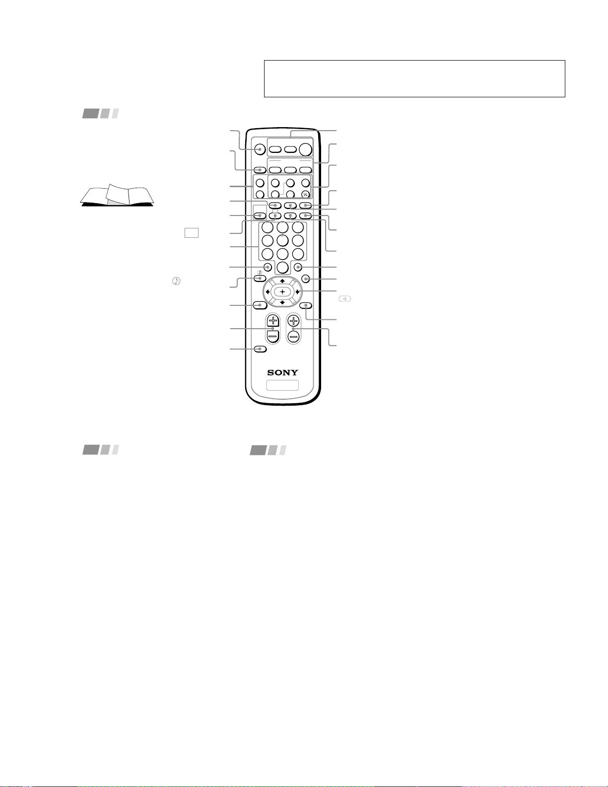
Getting to know the buttons on the
remote control
Names of the buttons on the remote control are
presented in different colors to represent the
available functions.
Button color
Transparent .... Press to select the component
you want to control; e.g. VTR
(VCR)/MDP/DVD Player,
CABLE, or projection TV.
Green ............... Buttons relevant to power
operations, like turning the
projection TV, CABLE, or VTR
(VCR)/MDP/DVD Player on
or off
Label color
White ............... TV/VTR (VCR)/MDP/DVD
Player/CABLE operation
buttons
Yellow .............. PIP operation buttons
Blue .................. SAT operation buttons*
Green ............... S-Link operation buttons
Pink .................. DVD Player operation buttons
For a detailed explanation of most buttons, see
“Watching the TV” on page 14.
Remote Control
MENU
(page 19)
POWER*
(pages 14, 31,
32)
FUNCTION*
(pages 14, 31,
32)
TV/VIDEO
(pages 15, 17)
ANT
(page 16)
MUTING
(page 14)
DISPLAY
(page 15)
VCR/DVD/MDP
operation buttons
(page 31)
CC
(page 16)
JUMP
(page 15)
PIP operation
buttons
(page 17)
MTS/SAP
(pages 16, 21)
ENTER
(page 14)
GUIDE*
V/v/B/b and
buttons
(page 19)
CH +/–
(page 14)
SYSTEM OFF
(page 16)
PICTURE MODE
(pages 14, 20)
0 – 9 buttons
(page 14)
(pages 16, 21)
/
INDEX*
RESET
(pages 17, 20, 21)
VOL +/–
(page 14)
CODE SET
(pages 30, 32)
SLEEP
(page 16)
* The blue-labeled SAT/CABLE
(POWER), SAT/CABLE
(FUNCTION), INDEX and
GUIDE buttons cannot operate
a satellite receiver (SAT) in
Argentine and Chile even if it is
connected to the projection TV.
TV
2
5
8
0
1
4
7
3
6
9
ENTER
JUMP
GUIDE
INDEX
RESET
MENU
CODE SET
VOL CH
POWER
MUTING
FREEZE
AUDIO
ANT
TV/VIDEO
DISPLAYMTS/SAP
CC
PICTURE
MODE
POSITION ACTIVE
SWAP PIP
TV/VTR
SYSTEM
OFF
DVD/VTR SAT/CABLE
TV
DVD/
VTR
SAT/
CABLE
FUNCTION
SLEEP
m
N
M
xz
X
TV
We recommend that you carefully review the
contents of the following four sections in the
order provided to ensure that you fully
understand the operation of your new
projection TV.
1
Installing and Connecting the
Projection TV
This section guides you through your
initial set up. It shows you how to install
your projection TV, to connect your new
components and to connect to the
antenna and cable.
2
Basic Set Up
This section teaches you the basic skills
needed to operate your new projection
TV, including Auto Set Up. It shows you
how to operate the remote control’s
special functions.
3
Using Your New Projection TV
This section shows you how to begin
using your new projection TV. It shows
you how to use your remote control’s
features.
Thank you for purchasing the Sony Color
Rear Video Projection TV.
This manual is for models KP-43T75A, KP-
43T75C, KP-53SV75A, KP-53SV75C and KP-
61SV75C.
Model KP-53SV75A is used for illustration
purposes.
The features you will enjoy include:
• FLASH FOCUS, allowing you to adjust
convergence automatically.
• Picture-in-Picture (PIP), allowing you to
view another TV channel, video or cable
image as a window picture.
• Favorite Channel, allowing you to
view and choose from eight of your
favorite channels
• Y/P
B
/P
R
inputs for DVD Player
connections.
• Three AUDIO/VIDEO/S VIDEO inputs.
Welcome!
1
Using This Manual
4
Adjusting Your Set Up (menus)
This section teaches you how to access
on-screen menus and adjust your
projection TV’s settings.
Instructions in this manual are written for the remote
control. Similar controls may be found on the projection
TV console.
– 8 –
2
Installing and Connecting the Projection TV (continued)
Safety
• Operate the projection TV only on 110-
220 V AC.
• The plug is designed, for safety purposes,
to fit into the wall outlet only one way. If
you are unable to insert the plug fully
into the outlet, contact Sony Authorized
Service Center.
• If any liquid or solid object should fall
inside the cabinet, unplug the projection
TV immediately and have it checked by
Sony Authorized Service Center before
operating it further.
• If you will not be using the projection TV
for several days, disconnect the power by
pulling the plug itself. Never pull on the
cord.
Precautions
Note on cleaning
Clean the cabinet of the projection TV with a
dry soft cloth. To remove dust from the
screen, wipe it gently with a soft cloth.
Stubborn stains may be removed with a cloth
slightly dampened with solution of mild
soap and warm water. Never use strong
solvents such as thinner or benzine for
cleaning.
If the picture becomes dark after using the
projection TV for a long period of time, it
may be necessary to clean the inside of the
projection TV. Consult qualified service
personnel.
Installing
• To prevent internal heat buildup, do not
block the ventilation openings.
• Do not install the projection TV in a hot
or humid place, or in a place subject to
excessive dust or mechanical vibration.
• Avoid operating the projection TV at
temperatures below 5° C (41° F).
• If the projection TV is transported
directly from a cold to a warm location,
or if the room temperature changes
suddenly, the picture may be blurred or
show poor color. In this case, please wait
a few hours to let the moisture evaporate
before turning on the projection TV.
• To obtain the best picture, do not expose
the screen to direct illumination or direct
sunlight. It is recommended to use spot
lighting directed down from the ceiling
or to cover the windows that face the
screen with opaque drapery. It is
desirable to install the projection TV in a
room where the floor and walls are not of
a reflective material.
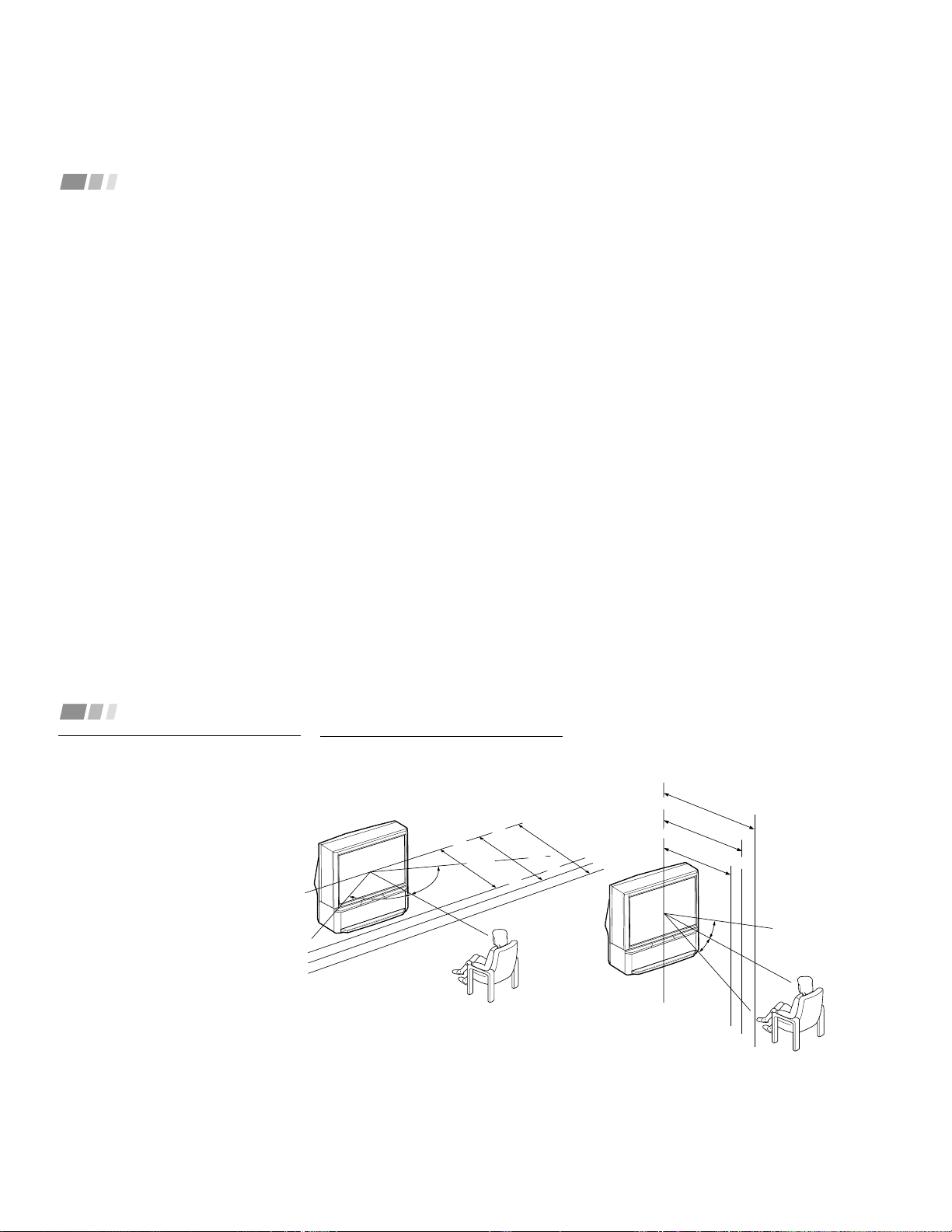
3
Installing and Connecting the Projection TV
Recommended viewing area
(Vertical)
Carrying Your Projection TV
Carrying the projection TV requires three or
more people.
For KP-53SV75A/53SV75C/61SV75C
The projection TV has been equipped with
casters for easy movement on a hard surface.
Please move your projection TV using the
casters.
Installing the Projection TV
Recommended viewing area
(Horizontal)
60°
60°
60°
min. 1.5m (approx. 5 ft.)
43"
min. 2.1m (approx. 7 ft.)
53"
min. 2.4m (approx. 8 ft.)
61"
20°
min. 2.1m (approx. 7 ft.)
53"
min. 2.4m (approx. 8 ft.)
61"
min. 1.5m (approx. 5 ft.)
43"
20°
– 9 –
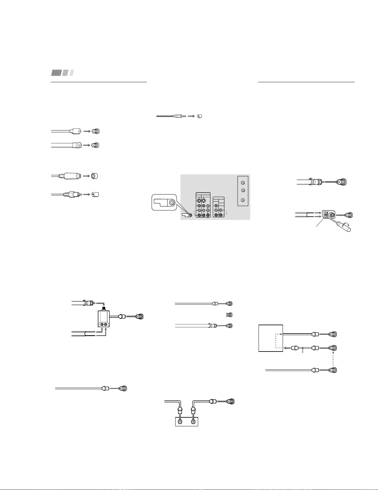
4
Installing and Connecting the Projection TV (continued)
Connector Types
You may find it necessary to use some of the
following connector types during set up.
Coaxial cable
Standard TV cable and antenna cable
S Video cable
High quality video cable for enhanced
picture quality
Audio/Video cable
Video - Yellow
Audio (Left) - White
Audio (Right) - Red
Some DVD Players are equipped with the
following three video connectors.
Y - Green
P
B
(C
B
, C
b
or B–Y) - Blue
P
R
(C
R
, C
r
or R–Y) - Red
Plug Type
Screw-on Type
Screw into connection.
Push into connection.
Align guides and
push into connection.
Push into connection.
CONTROL S cable
Sony cable for CONTROL S connection. This
feature is exclusive to Sony products and
allow greater control of all Sony equipment.
About the CONTROL S OUT jack
To control other Sony equipment with the
projection TV’s remote control, connect the
CONTROL S IN jack of the equipment to the
CONTROL S OUT jack on the projection TV
with the CONTROL S cable.
(Rear of
projection TV)
VHF/UHF
300-ohm twin
lead cable
75-ohm
coaxial cable
Push into connection.
(Rear of
projection TV)
VHF/UHF
Making Connections
Connecting directly to a cable or
an antenna
The connection you choose will depend on
the cable found in your home. Newer homes
will be equipped with standard coaxial cable
(see
A
); older homes will probably have 300 -
ohm twin lead cable (see
B
); still other
homes may contain both (see
C
).
Use 75-ohm coaxial cable for improved
picture quality (see
A
).
A
• VHF only
or
• VHF/UHF
or
• Cable
B
• VHF only
or
• UHF only
or
• VHF/UHF
(Rear of projection TV)
S VIDEO
CONTROL S
OUT
VIDEO
AUDIO
L
R
VIDEO
VHF/UHF
AUX
(MONO)
IN
VIDEO 1 VIDEO 3
OUT
MONITOR AUDIO
(VAR/FIX)
TO
CONVERTER
Y
P
B
P
R
R
L
(MONO)
AUDIO
COMPONENT
CONTROL S
OUT
Antenna connector
5
C
• VHF
and
• UHF
Cable or antenna
This is the simplest connection. Connection is
made directly from the cable or antenna to
the projection TV.
Cable and antenna
You may find it convenient to use the
following set up if your cable provider does
not feature local channels that you are able to
receive using an antenna.
Antenna cable
VHF/UHF
Select Cable or ANT mode by pressing ANT
on the remote control.
Connecting a cable box
Some pay cable TV systems use scrambled or
encoded signals that require a cable box* to
view all channels.
Also, set “Cable” to “Sí” in the Ajuste de
canal menu (page 25).
(Rear of projection TV)
VHF/UHF
Coaxial cable
(Rear of projection TV)
AUX
Coaxial cable
(No connection “TO
CONVERTER” in this case)
TO CONVERTER
Cable box and cable
Some pay cable TV systems use scrambled or
encoded signals requiring a cable box* only for
certain channels (e.g. HBO, CNN, etc.)
For this set up, you can switch between
scrambled channels (through your cable
box), and normal (CATV) channels by
pressing ANT on your remote control.
Notes:
• You may be able to program your Sony
remote control to operate your cable box.
(see “Operating a Cable Box” on page 32)
• During PIP or Canal favorito viewing, the
AUX input can only be viewed in the
main picture.
*Cable box
Coaxial cable
OUT
IN
(Rear of projection TV)
VHF/UHF
*Cable box
VHF/UHF
(Rear of projection TV)
AUX
CATV cable
(unscrambled channels)
Scrambled
channels
TO CONVERTER
(Signal)
75-ohm coaxial cable
(not supplied)
75-ohm coaxial cable
EAC-66 U/V mixer
(not supplied)
300-ohm twin lead cable
(Rear of
projection TV)
VHF/UHF
– 10 –
6
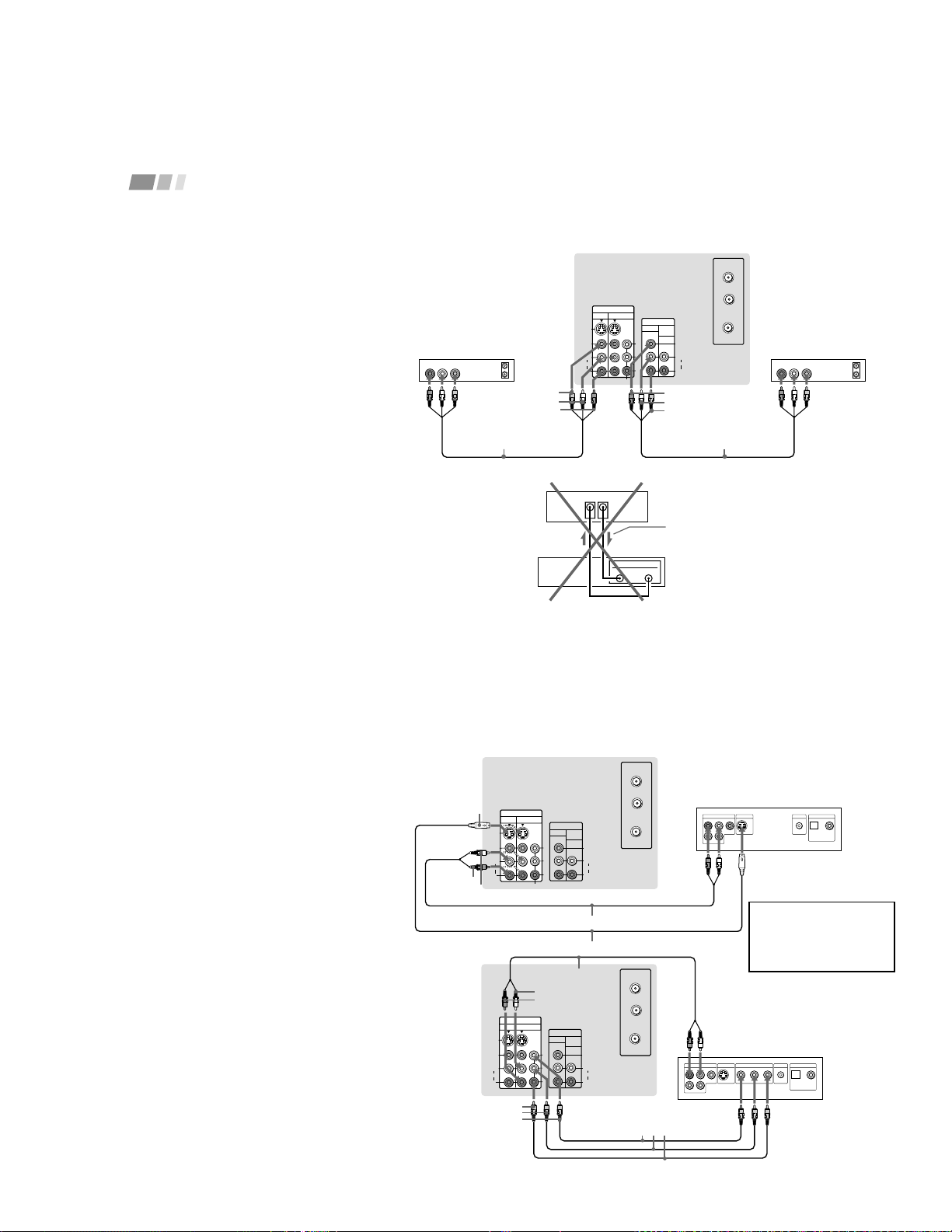
Installing and Connecting the Projection TV (continued)
Connecting a cable TV system/
antenna to a VCR
1
Attach the coaxial cable from the
incoming cable connection or antenna to
VHF/UHF IN on the VCR.
2
Using a coaxial cable, connect VHF/UHF
OUT on the VCR to VHF/UHF on the
projection TV.
3
Using AUDIO and S VIDEO* cables,
connect AUDIO and S VIDEO OUT on the
VCR to AUDIO and S VIDEO IN on the
projection TV (White-AUDIO Left, Red-
AUDIO Right**).
Connecting a VCR and projection
TV to a cable box
1
Connect the single (input) jack of the
splitter to the incoming cable connection,
and connect the other two (output) jacks
(using the coaxial cable) to IN on the cable
box and VHF/UHF on the projection TV.
2
Using a coaxial cable, connect OUT on the
cable box to VHF/UHF IN on the VCR.
3
Using AUDIO and S VIDEO* cables,
connect AUDIO and S VIDEO OUT on the
VCR to AUDIO and S VIDEO IN on the
projection TV (White-AUDIO Left, Red-
AUDIO Right**).
Disconnect all power sources before making any connections.
(Rear of projection TV)
(Rear of projection TV)
VMC-810S/820S
(not supplied)
YC-15V/30V
(not supplied)
2
1
Cable/
Antenna
Coaxial cable
AUDIO-L
AUDIO-R
VIDEO
S VIDEO
VMC-810S/820S
(not supplied)
YC-15V/30V
(not supplied)
AUDIO-L
AUDIO-R
VIDEO
S VIDEO
Cable/
Antenna
Splitter (not supplied)
Cable box
1
Coaxial cable
2
VCR
VCR
S VIDEO
VIDEO
AUDIO
L
R
VIDEO
VHF/UHF
AUX
(MONO)
IN
VIDEO 1 VIDEO 3
OUT
MONITOR AUDIO
(VAR/FIX)
TO
CONVERTER
Y
P
B
P
R
R
L
(MONO)
AUDIO
COMPONENT
LINE
OUT
OUT
IN
AUDIO R AUDIO L VIDEO
S VIDEO
VHF/UHF
LINE
IN
3
S VIDEO
VIDEO
AUDIO
L
R
VIDEO
VHF/UHF
AUX
(MONO)
IN
VIDEO 1 VIDEO 3
OUT
MONITOR AUDIO
(VAR/FIX)
TO
CONVERTER
Y
P
B
P
R
R
L
(MONO)
AUDIO
COMPONENT
LINE
OUT
OUT
IN
AUDIO R AUDIO L VIDEO
S VIDEO
VHF/UHF
LINE
IN
OUT
IN
3
7
Disconnect all power sources before making any connections.
Note:
• To view scrambled channels through the
cable box, select the video input which the
cable box is connected to by pressing TV/
VIDEO.
* If your VCR is not equipped with S VIDEO, use
a VIDEO cable (yellow) instead of the S VIDEO
cable.
** If you are connecting a monaural VCR, connect
only the single audio output to the left (MONO)
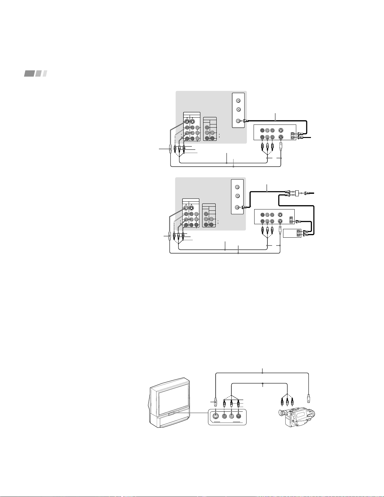
input on the projection TV.
Connecting a camcorder
Use this connection to view a picture directly
from your camcorder.
1
Using AUDIO and S VIDEO* cables,
connect AUDIO and S VIDEO OUT on
the camcorder to AUDIO and S VIDEO
IN inside the drop-down panel on the
front of the projection TV (White-AUDIO
Left, Red-AUDIO Right**).
2
Press VIDEO 2 to select the video inputs
from a camcorder.
* If your camcorder is not equipped with S
VIDEO, use a VIDEO cable (yellow) instead of
the S VIDEO cable.
** If you are connecting a monaural camcorder,
connect only the single audio output to the left
(MONO) input on the projection TV.
S VIDEO
VIDEO
L
(MONO)
R
AUDIO
VIDEO 2 INPUT
(Front of projection TV)
Camcorder
VMC-810S/820S
(not supplied)
YC-15V/30V (not supplied)
VIDEO
AUDIO-L
AUDIO-R
S VIDEO
Audio/
video
outputs
S VIDEO
OUT
– 11 –
8
Installing and Connecting the Projection TV (continued)
S VIDEO
VIDEO
AUDIO
L
R
VIDEO
VHF/UHF
AUX
(MONO)
IN
VIDEO 1 VIDEO 3
OUT
MONITOR AUDIO
(VAR/FIX)
TO
CONVERTER
Y
P
B
P
R
R
L
(MONO)
AUDIO
COMPONENT
AUDIO R AUDIO L VIDEO
LINE
OUT
OUT
IN
AUDIO R AUDIO L VIDEO
LINE
IN
OUT
IN
Disconnect all power sources before making any connections.
(Rear of projectionTV)
Indicates direction
of signal
Connecting two VCRs for tape
editing
By connecting a second VCR to MONITOR
OUT, you can record a program being played
by the primary VCR to the second VCR or
perform tape editing and dubbing.
1
Connect the VCR intended for playback
using the connection instructions on page
6 of this manual.
2
Using an AUDIO/VIDEO cable, connect
AUDIO and VIDEO IN on the VCR
intended for recording to AUDIO and
VIDEO OUT of MONITOR OUT on the
projection TV.
Notes:
• Do not change the input signal while
editing through MONITOR OUT.
• When connecting a single VCR to the
projection TV: if VCR LINE OUT is
connected to VIDEO IN on the projection
TV, do not connect MONITOR OUT on
the projection TV to the VCR LINE
INPUT (see right). Doing so will cause
program interference and other viewing
problems.
VIDEO
AUDIO-L
AUDIO-R
(Rear of projection TV)
VCR (for recording)
1
2
VMC-810S/820S
(not supplied)
VCR (for playback)
VMC-810S/820S
(not supplied)
LINE
OUT
IN
MONITOR
OUT
VIDEO IN
VCR
AUDIO-L
VIDEO
AUDIO-R
9
S VIDEO
VIDEO
AUDIO
L
R
VIDEO
VHF/UHF
AUX
(MONO)
IN
VIDEO 1 VIDEO 3
OUT
MONITOR AUDIO
(VAR/FIX)
TO
CONVERTER
Y
P
B
P
R
R
L
(MONO)
AUDIO
COMPONENT
LINE OUT
S VIDEO OUT
S-LINK
DIGITAL OUT
R–AUDIO 1–L VIDEO
OPTICAL COAXIAL
S VIDEO
VIDEO
AUDIO
L
R
VIDEO
VHF/UHF
AUX
(MONO)
IN
VIDEO 1 VIDEO 3
OUT
MONITOR AUDIO
(VAR/FIX)
TO
CONVERTER
Y
P
B
P
R
R
L
(MONO)
AUDIO
COMPONENT
LINE OUT
S VIDEO OUT
S-LINK
DIGITAL OUT
R–AUDIO 1–LVIDEO
OPTICAL COAXIAL
R-YYB-Y
COMPONENT VIDEO OUT
Disconnect all power sources before making any connections.
Connecting a DVD Player (Upper
illustration)
Using an AUDIO and S VIDEO cables,
connect AUDIO and S VIDEO IN on the
projection TV to AUDIO and S VIDEO OUT
on the DVD Player (White-AUDIO Left, Red-
AUDIO Right).
Connecting a DVD Player with
component video output
connectors (Lower illustration)
1
Using an AUDIO cable, connect AUDIO of
LINE OUT on the DVD Player to AUDIO of
VIDEO 3 IN on the projection TV (White-
AUDIO Left, Red-AUDIO Right).
2
Using three yellow VIDEO cables,
connect Y, P
B
, and P
R
of COMPONENT
VIDEO OUT on the DVD Player to Y, P
B
,
and P
R
of VIDEO 3 IN on the projection
TV.
Note:
• Some DVD Player terminals may be labeled
differently. If so, connect as follows:
Connect Y (green) to Y.
Connect P
B
(blue) to C
B
, C
b
or B-Y.
Connect P
R
(red) to C
R
, C
r
or R-Y.
AUDIO-L
DVD
YC-15V/30V (not supplied)
(Rear of projection TV)
Audio/S video
outputs
AUDIO-R
S VIDEO
RK-74A (not supplied)
AUDIO-R
DVD
(Rear of
projection
TV)
Connect the DVD Player
directly to the projection TV.
Connecting the DVD Player
through other video
equipment will cause
unwanted picture noise.
P
R
P
B
Y
VMC-10HG
(not supplied)
RK-74A (not supplied)
AUDIO-L
– 12 –
10
Installing and Connecting the Projection TV (continued)
(Rear of projection TV)
RK-74A
(not supplied)
Line inputs
AUDIO-L
(white)
Stereo amplifier
AUDIO-R
(red)
S VIDEO
CONTROL S
OUT
VIDEO
AUDIO
L
R
VIDEO
(MONO)
IN
VIDEO 1 VIDEO 3
OUT
MONITOR AUDIO
(VAR/FIX)
Y
R
L
(MONO)
AUDIO
COMPONENT
HRD
Disconnect all power sources before making any connections.
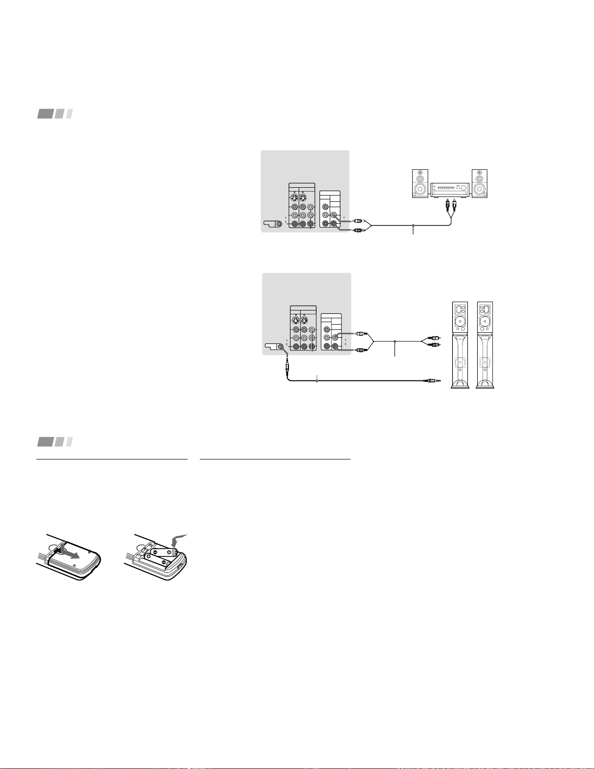
Connecting an audio system (Upper
illustration)
For more dynamic sound, connect an audio system to
the projection TV.
1
Using an AUDIO cable, connect AUDIO (VAR/FIX)
OUT on the projection TV to one of the unused Line
inputs (e.g. Tape-2, AUX1, etc.) on the stereo.
2
Set the stereo to the chosen Line input and use the
Audio menu to set the audio output and switch the
TV’s speakers off. (see “Salida de audio” and
“Parlantes” on page 22)
Note:
• You can adjust VOLUME, “Graves,” “Agudos,”
“Balance,” “MTS/SAP” and “Efecto” with the
supplied remote control. The control items except
VOLUME can be adjusted only when “Salida de
audio” is set to “Variable” in the Audio menu. (see
“Salida de audio” on page 22)
Connecting a Sony SAVA series speaker
system (Lower illustration)
Use this connection to control the speaker’s Dolby Pro
Logic surround system and super woofer mode with the
remote control. (see “Control SAVA SP ” on page 22)
1
Using the AUDIO cable supplied with the speaker to
AUDIO (VAR/FIX) OUT on the projection TV.
2
Using the CONTROL S cable, connect CONTROL S
IN on the speaker to CONTROL S OUT on the
projection TV.
(Rear of projection TV)
AUDIO-L
(white)
AUDIO-R (red)
Audio cord supplied
with the speakers
CONTROL S IN
RK-G34, etc. (not supplied)
1 IN L
1 IN R
2
SAVA series
speaker system
1
CONTROL S
OUT
S VIDEO
CONTROL S
OUT
VIDEO
AUDIO
L
R
VIDEO
(MONO)
IN
VIDEO 1 VIDEO 3
OUT
MONITOR AUDIO
(VAR/FIX)
Y
P
B
P
R
R
L
(MONO)
AUDIO
COMPONENT
11
Using the Remote Control
Inserting the batteries
Insert two size AA (R6) batteries (supplied)
by matching the + and – on the batteries to
the diagram inside the remote control’s
battery compartment.
Basic Set Up
Notes:
• Remove the batteries to avoid damage
from possible battery leakage whenever
you anticipate that the remote control
will not be used for an extended period.
• Handle the remote control with care.
Avoid dropping it, getting it wet, or
placing it in direct sunlight, near a heater
or where the humidity is high.
• Your remote control can be programmed to
operate most video equipment.
(see “Operating Video Equipment” on
page 30)
(continued)
Notes:
• Before you perform AUTO SET UP again,
make sure that the input from ANT (not
AUX) is selected by pressing ANT until
“AUX” does not appear next to the
channel number.
• Perform this function during the day,
with the antenna and/or cable properly
connected, to ensure that all available
channels will be broadcasting and
receivable.
• When you perform AUTO SET UP, all the
settings in the Video, and Audio menus
are reset to the factory settings.
Setting Up the Projection TV
Automatically
The AUTO SET UP feature will allow you to
set the on-screen language and set all
receivable channels.
The AUTO SET UP feature does not apply for
installations that use a cable box for all channel
selection.
You can also set up the projection TV manually.
(see “Using the Ajuste de canal Menu” on pages
24 and 25)
– 13 –
12
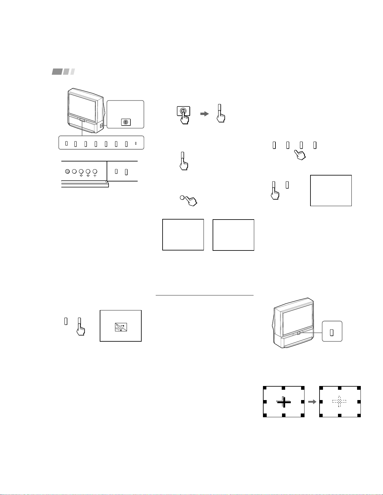
2 Press POWER on the projection TV.
The TIMER/STANDBY indicator
lights in green.
For KP-43T75C/53SV75C/61SV75C
only
Press POWER on the projector TV.
2
Press SET UP inside the drop-down
panel.
The AUTO SET UP screen appears.
VOLUME
– +
VOLUME
– +
CHANNEL
– +
No :
Auto Programación?
¿Continuar
S í :
[CH– ]
[CH+]
POWER
Auto Set Up :
Españ ol :
English :
Franç ais :
[VOL– ]
[CH– ]
[CH+]
[VOL+]
Oprima
[
SET UP
]
para
salir.
Primero conecte el
cable/antena.
POWER
MAIN POWER
Basic Set Up (continued)
1
Turn on the projector TV.
For KP-43T75A/53SV75A only
1 Depress MAIN POWER on the right
side of the porjection TV.
The projection TV enters standby mode
and the TIMER/STANDBY indicator
lights in red.
TV/VIDEO
FLASH FOCUS
MENUSET UP
TV/VIDEO
FLASH FOCUS
VOLUME
POWER
TIMER/STAND BY
– +
CHANNEL
– +
MAIN POWER
KP-43T75A/
53SV75A
only
Inside the drop-down panel
Right side
Front panel
Auto Set Up :
Españ ol :
English :
Portuguê s :
[VOL– ]
[CH– ]
[CH+]
[VOL+]
Oprima
[
SET UP
]
para
salir.
Primero conecte el
cable/antena.
SET UP
KP-43T75A/53SV75A
only
KP-43T75C/53SV75C/
61SV75C only
3
Press CHANNEL +, CHANNEL – or
VOLUME + to select the desired on-
screen language: English, Español or
Português (KP-43T75A/53SV75A), or
English, Español or Français (KP-
43T75C/53SV75C/61SV75C).
The screen will change to reflect your
choice.
4
Press VOLUME – to continue.
13
5
Press CHANNEL + to preset channels
automatically.
“Auto Programación” appears and the
projection TV starts scanning and
presetting channels automatically. While
scanning, the received channel will be
displayed on the sub screen. When all the
receivable channels are stored, the lowest
numbered channel is displayed.
To perform AUTO SET UP again
Press SET UP inside the drop-down panel on
the projection TV and perform steps 3-5 on
pages 12 and 13.
Press SET UP again to exit.
CHANNEL
– +
Adjusting the Convergence
Automatically (FLASH FOCUS)
The projection tube image appears on the
screen in three layers (red, green and blue). If
they do not converge, the color is poor and
the picture blurs.
Before you use your projection TV, be sure to
adjust the convergence.
The FLASH FOCUS feature allows you to
adjust the convergence automatically.
Tips
z
• It is recommended to perform FLASH FOCUS about
30 minutes after the projection TV is first turned on.
• You can also perform FLASH FOCUS using the
Ajustes menu on page 29.
Press FLASH FOCUS.
The cross pattern appears and FLASH
FOCUS begins to work. The adjustment is
completed when the cross pattern becomes
white.
Note:
• FLASH FOCUS is canceled if you
perform any other function while FLASH
FOCUS is working.
Auto Programación
FLASH FOCUS
– 14 –
14
Using Your New Projection TV (continued)
MAIN POWER
(on the right side
of the projection
TV)
TV (FUNCTION)
TV POWER
CH +/–
VOL +/–
MUTING
Switches the projection TV on and off.
Activates the remote control for use with the projection TV.
Turns the projection TV on and off. If a video input indication (e.g., VIDEO 1,
VIDEO 2) appears on the screen, press TV/VIDEO until a channel number
appears.
Use for direct channel selection. Press 0-9 to select a channel (for example,
to select channel 10, press 1 and 0). The channel will change after 2
seconds, or you can press ENTER for immediate selection.
Press to scan through the channels (+ up or – down).
Speed Surf
1 Press and hold CH + or – to change the channel number rapidly.
2 Release to display the desired channel.
Press to adjust the volume (+ up or – down).
Press to mute the sound. “Suprimir el sonido” will appear on the screen and
will dim three seconds later. To restore sound, press again or press VOL +.
Watching the TV
Many TV features can be accessed directly
through the remote control. The following
chart will explain the function of some
buttons found on your remote control.
Using the White Labeled Buttons for Projection TV Operations
and ENTER
0 9
-
PICTURE MODE
Press PICTURE MODE repeatedly to directly
choose one of five different video modes that
best suits the program you are watching.
Vívido: Select for enhanced picture contrast
and sharpness.
Estándar: Select to display a standard
picture for normal viewing environments.
Películas: Select to display a finely detailed
picture for low light environments.
Personal 1, Personal 2: Select to customize
the “Ajuste de imagen” of the Video menu
according to your personal preference.
When you select “Películas,” “Personal 1” or
“Personal 2,” you can also perform the “Ajuste
de imagen” (such as “Brillo,” “Color,” etc.) to
suit your taste. For details, see “Modo” on page
20.
15
TV/VIDEO
JUMP
FREEZE
(yellow labeled
button)
DISPLAY
Press repeatedly to scroll through available video inputs:
TV, VIDEO 1, VIDEO 2 and VIDEO 3.
If you select “Omitir” as a “Etiqueta de video” in the Ajustes menu, your
projection TV will skip the video input you selected. (see “Etiqueta de video”
on page 29)
Press to alternate or
jump
back and forth between two channels. The
projection TV will jump between the current channel and the last channel
selected using the 0-9 buttons.
This is useful when you need to copy down information that appears on the
TV’s screen.
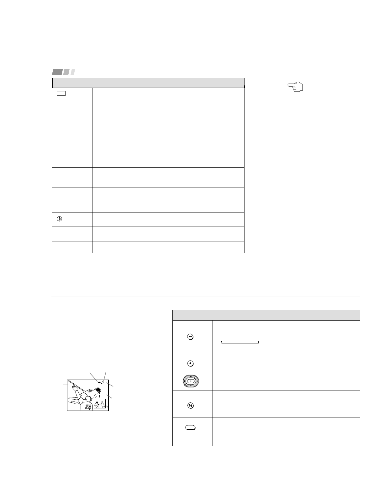
Press to
freeze
the desired picture. The frozen picture is displayed in the
window picture while viewing the normal picture of the current channel in the
main picture.
To change the location of the window picture, press V, v, B or b.
Press FREEZE again to display the normal picture.
Press to display the channel number, current time, channel caption (if set),
and MTS/SAP mode (if SAP is selected). The SAP indication disappears and
the other indications dim three seconds later.
To turn the display off, press DISPLAY again.
Using the White Labeled Buttons for Projection TV Operations
Frozen picture
Normal motion
picture
REFER TO THE
ILLUSTRATION OF THE
REMOTE CONTROL ON THE
INSIDE FRONT COVER OF
THIS MANUAL AS YOU
REVIEW THIS CHART
(continued)
6
Receta
harina - - - - 2
azúcar - - 1/2
sal- - - - - - 1/2
mantequilla - 1
– 15 –
16
Using Your New Projection TV (continued)
CC
SLEEP
ANT
(AUX input)
MTS/SAP
TV/VTR
SYSTEM OFF
Press repeatedly to scroll through available displays:
XDS (Extended Data Service)
Displays a network name, program name, program type, program length,
program description, call letters and time of the show if the broadcaster
offers this service.
Caption Vision
Displayed on the screen if the broadcaster offers this service. (see
“Caption Vision” on page 28)
No display
“Off” appears and the display is canceled.
Press repeatedly until the projection TV displays the approximate time in
minutes (30, 60, or 90) that you want the projection TV to remain on before
shutting off automatically.
Cancel by pressing until “Sleep Off” appears.
Press to change between the VHF/UHF input and the AUX input. (for
detailed connection information, see “Cable and antenna” or “Cable box and
cable” on page 5)
Press to scroll through the Multi-channel TV Sound (MTS) options:
Estéreo, SAP and Mono (KP-43T75A/53SV75A) ; Estéreo, SAP, Mono
and SAP auto (KP-43T75C/53SV75C/61SV75C).
(see “MTS/SAP” on page 21)
Press to select an audio option:
Simulado, ,No, BBE and Surround. (see “Efecto” on page 21)
Press when you are finished using a VCR and you want to switch to the TV
input. The VCR power will remain on.
Press to turn off the projection TV and all other Sony equipment.
Using the White Labeled Buttons for Projection TV Operations
REFER TO THE
ILLUSTRATION OF THE
REMOTE CONTROL ON THE
INSIDE FRONT COVER OF
THIS MANUAL AS YOU
REVIEW THIS CHART
17
The Picture-in-Picture (PIP) feature allows
you to view two channels simultaneously,
one in the full size “main” picture and one in
a smaller “window” picture.
You can move the window picture to any
location on the screen.
* It will dim in about 3 seconds.
Tip
z
If you press RESET in PIP mode, the window picture
will move to the bottom right (factory-preset location).
6
10
(white labeled
button)
Press to display a window picture.
Each time you press this button, the picture size will change
(1/9 n1/16 nno display).
To close the window picture, press PIP repeatedly until it disappears.
Press POSITION repeatedly to change the location of the window picture
(counterclockwise) around the main picture.
You can also change the location by pressing the V, v, B or b button.
The window picture moves in the direction of the arrow indicated on the
pressed button.
Press to select either the main or window picture in order to change the
TV channel or video source using the white labeled buttons below. The
symbol “b” (or “B”) will appear to indicate which picture’s channel or input
mode can be changed.
Press repeatedly to scroll through the available video inputs for the
picture on which the symbol “b” (or “B”) is displayed. (see “TV/VIDEO” on
page 15)
Watching Two Programs at One Time — PIP
Using the Yellow Labeled Buttons for PIP Operations
Main
picture
The symbol “≥”
indicates which
picture's sound is being
received.
TV channel or input-
source mode for the
main picture* (yellow-
green-colored)
TV channel or input-
source mode for the
window picture*
(white-colored)
Window
picture
The symbol “b” or “B”
indicates which picture's
TV channel or input
source can be changed.
TV/VIDEO
PIP
POSITION
ACTIVE
or
– 16 –
18
Using Your New Projection TV (continued)
(white labeled button)
(white labeled
button)
Press to select the TV channel on which the symbol “b” is
displayed. (for details, see “Watching the TV” on page 14)
Speed Surf
1 Press and hold CH + or – to change the channel number rapidly.
2 Release to display the desired channel.
Press to change between the VHF/UHF input and the AUX input for the picture on
which the symbol “b” (or “B”) is displayed.
Press to alternate sound between the main picture and the window picture. The
symbol “
” will appear for a few seconds to indicate which picture’s sound is being
received.
This is useful when you need to copy down information of the main picture.
Press to freeze the desired scene in the main picture. The frozen picture is displayed
in the window picture while viewing the normal picture in the main picture. The
window picture size is automatically changed to 1/9 if it was 1/16.
Press again to resume normal PIP viewing.
Press to switch the audio and video of the main picture and the window picture.
Each time you press SWAP, the picture and sound of the two will be exchanged.
Using the Yellow Labeled Buttons for PIP Operations
Note:
• If one of the pictures received through
PIP is snowy, the entire screen may
become unstable. In this case, erase the
snowy channel. (see “Canal omitir/
agregar” on page 25)
REFER TO THE
ILLUSTRATION OF THE
REMOTE CONTROL ON THE
INSIDE FRONT COVER OF
THIS MANUAL AS YOU
REVIEW THIS CHART
CH
or or
0 9
-
JUMP
and ENTER
ANT
AUDIO
FREEZE
SWAP
19
Some adjustment menus may require
further operations. For details, see each
menu option.
To return to the previous screen (except
for the slider adjustment menus), choose
“ ” at the bottom of the menu and press
or B.
6
Once you have completed all menu
corrections, press MENU to exit the menu
screens.
To exit from the menus at any
time
Press MENU.
Tip
z
You can also use the MENU, / and buttons
inside the front drop-down panel of the projection TV
for the menu selection.
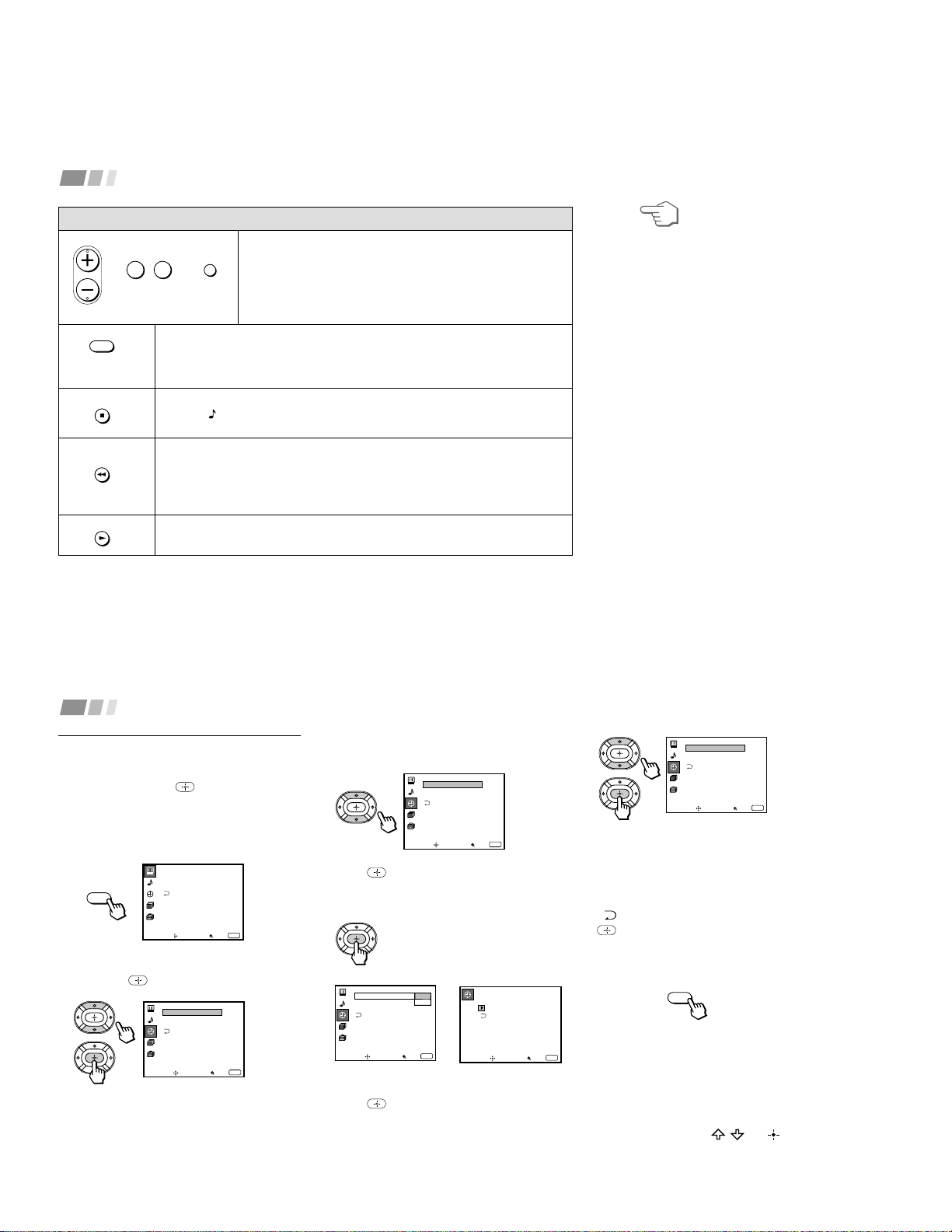
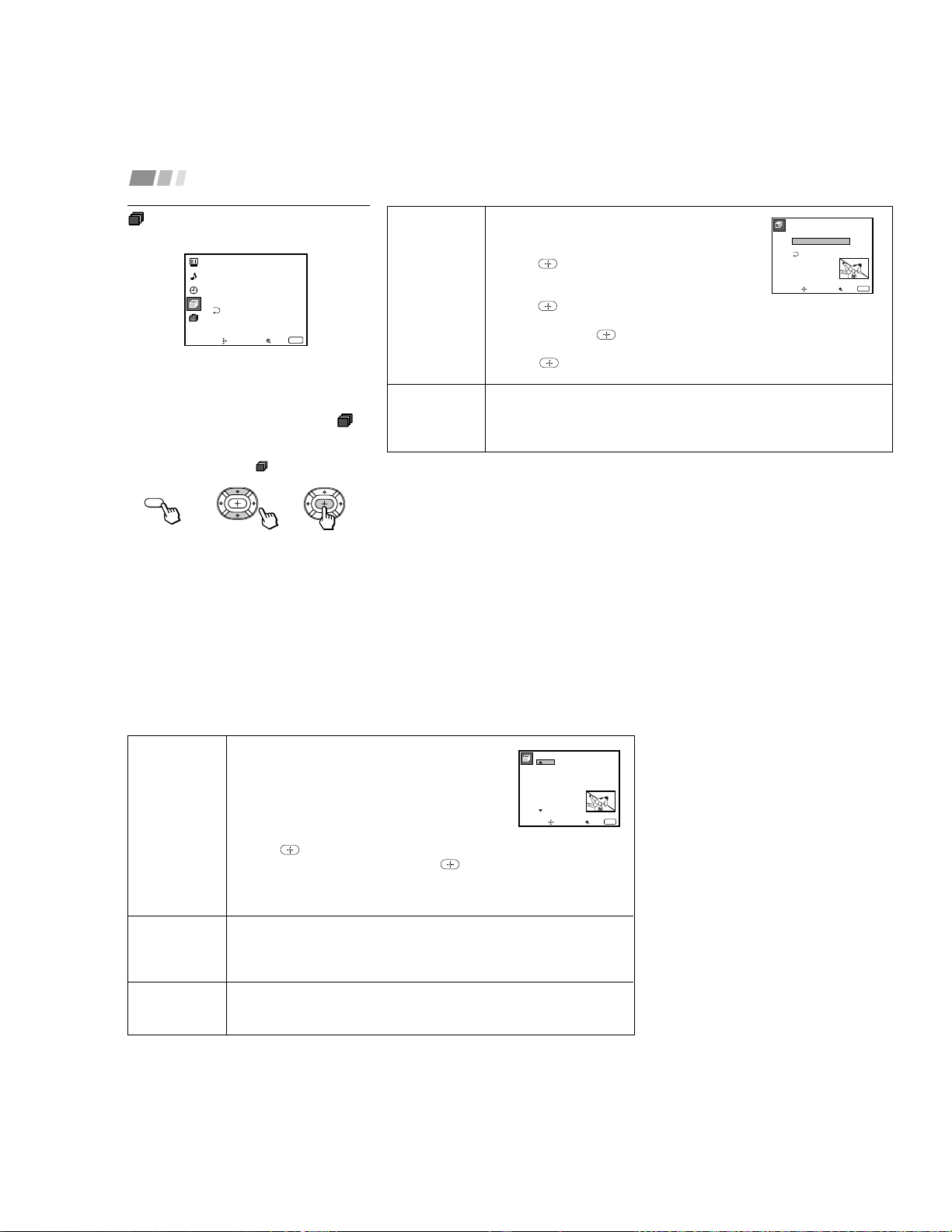
Learning Menu Selection
Use the MENU button to access a menu and
use the V, v, B, b and buttons to alter the
settings. Use the following example to learn
how to modify settings.
1
Press the MENU button.
The main menu appears.
2
Press V or v to highlight the desired menu
and press to activate it.
You may also press b to activate your
selection.
3
Press V or v to highlight the desired
option.
4
Press .
Options for your selection (Pop-up menu
or Adjusting menu) will be displayed.
5
Press V or v to make your selection and
press to activate it.
The previous screen will reappear.
Pop-up menu Adjusting menu
MENU
MENU
Adjusting Your SET UP (menus)
Video
Modo: Ví vido
Ajuste de imagen
Trinitone: Alto
Mover Seleccionar
Salir
MENU
ch
Reloj
Hora de verano: Sí
Fijar hora actual
Cronó metro
----- : - AM-
ch
Mover Seleccionar
Salir
MENU
Reloj
Hora de verano: Sí
Fijar hora actual
Cronó metro
----- : - AM-
ch
Mover Seleccionar
Salir
MENU
Reloj
Hora de verano: No
Fijar hora actual
Cronó metro
----- : - AM-
ch
Mover Seleccionar
Salir
MENU
Reloj
Hora de verano: Sí
Fijar hora actual No
Cronó metro
----- : - AM-
ch
Mover Seleccionar
Salir
MENU
Fijar hora actual
–––
––: – AM–
Mover Seleccionar
Salir
MENU
– 17 –
20
Adjusting Your SET UP (menus) (continued)
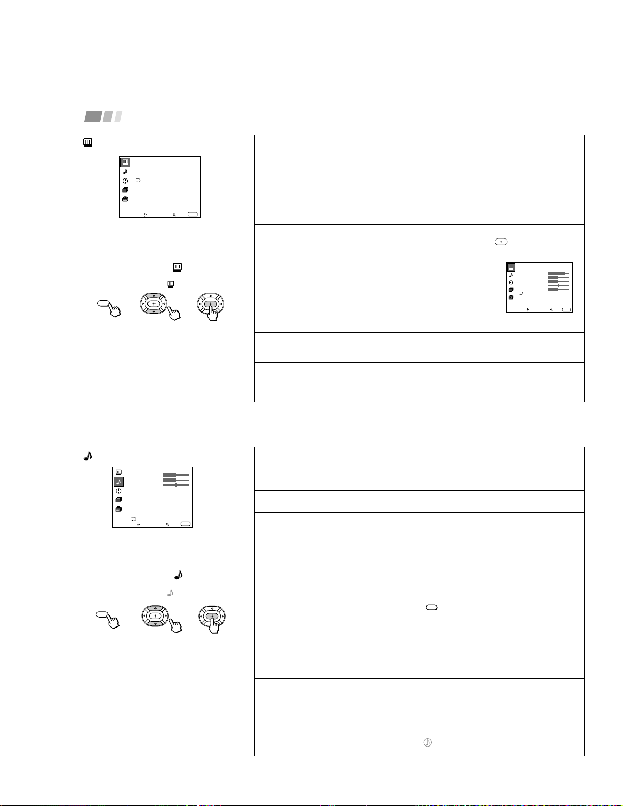
Modo
Customized
picture viewing
Ajuste de imagen
Picture adjustment
Trinitone
White intensity
adjustment
Reduccion de
ruldo
Nose reduction
You can choose one of five different video modes that best suits the program you
are watching. You can also perform the “Ajuste de imagen” (such as “Brillo,”
“Color,” etc.) for “Películas,” “Personal 1” or “Personal 2” to suit your taste.
Vívido: Select for enhanced picture contrast and sharpness.
Estándar: Select to display a standard picture for normal viewing
environments.
Películas: Select to display a finely detailed picture for low light environments.
Personal 1, Personal 2: Select to customize the “Ajuste de imagen” of the
Video menu according to your personal preference.
Press PICTURE MODE on the remote control for direct selection of a “Modo
”
setting.
First select “Películas,” “Personal 1” or “Personal 2” from “Modo,” then highlight
the desired option using the V or v button and press
to display the adjusting
slider of the selected option.
Contraste: Adjust slider right (up) to increase picture
contrast; left (down) to decrease it.
Brillo: Adjust slider right (up) to brighten the
picture; left (down) to darken it.
Color: Adjust slider right (up) to increase color
intensity; left (down) to decrease it.
Tinte: Adjust slider right (up) to increase the green
tones; left (down) to increase the red tones.
Nitidez: Adjust slider right (up) to sharpen the
picture; left (down) to soften it.
Alto: Select to give the white colors a blueish tint.
Medio: Select to give the white colors a neutral tint.
Normal: Select to give the white colors a reddish tint.
“Reduccion de ruido” can only be set when the TV input is selected and “Modo”
of the Video menu is set to “Peliculas,” “Personal 1”or “Personal 2”.
Select Si toreduce picture noise.
Select No to cancel the feature.
To restore the factory settings
Press RESET on the remote control while the
Video menu is selected. To restore each
“Modo” to the factory setting, press RESET
after selecting the mode to be reset.
Using the Video Menu
For detailed information on using the remote
control to modify menu settings, refer to
“Learning Menu Selection” on page 19.
To select the Video menu:
Display
/
Highlight
/
Select
MENU
Video
Modo: Ví vido
Ajuste de imagen
Trinitone: Alto
Mover Seleccionar
Salir
MENU
ch
Personal 1
Contraste
Tinte
Color
Brillo
Nitidez
ch
MENU
Mover Seleccionar
Salir
21
Agudos
Sound adjustment
Graves
Sound adjustment
Balance
Sound adjustment
MTS/SAP
Enjoy stereo,
bilingual and mono
programs.
Auto Volumen
Adjust the sound
level.
Efecto
Customizes
surround sound
effects based on the
program’s audio
type.
Adjust slider right (up) to increase high pitched sounds.
Adjust slider left (down) to decrease high pitched sounds.
Adjust slider right (up) to increase low pitched sounds.
Adjust slider left (down) to decrease low pitched sounds.
Adjust slider right (up) to emphasize right speaker volume.
Adjust slider left (down) to emphasize left speaker volume.
When the sound is intermittent due to poor reception conditions, select “Estéreo”
or “SAP.”
Estéreo: Select for stereo reception when viewing a program broadcast in
stereo.
SAP: Select to listen to a bilingual broadcast. (non-SAP programs will be muted
when this feature is selected)
Mono: Select for mono reception. (use to reduce noise during stereo broadcasts)
SAP auto: Select to listen to SAP when a SAP program is broadcast and return
to stereo reception automatically for non-SAP programs. (KP-43T75C/
53V75C/61SV75C ONLY)
Quick MTS access: Press
MTS/SAP
on the remote control to cycle through the
“MTS/SAP” options as follows:
Estéreo
n
SAP
n
Mono (KP-43T75A/53V75A)
Estéreo
n
SAP
n
Mono
n
SAP auto (KP-43T75C/53SV75C/61SV75C)
Sí:
Sound output coming from TV speakers have the volume level equalized for all
channel audio inputs when broadcasts have different sound transmission levels.
No:Sound output coming from the TV speakers varies according to the received
channel.
“Efecto” can only be set when “Parlantes” is set to “Sí” or “No.”
Simulado: Adds a surround-like effect to mono programs.
Surround: Simulates sound with the atmosphere of a movie theater or a concert
hall for stereo programs.
BBE*: Centers the sound intensity to the front, creating an effect as if you were
seated in front of an orchestra.
No: Normal stereo or mono reception.
Quick Effect access:
Press on the remote control to cycle through the
“Efecto” options as follows: Simulado
n
Surround
n
BBE
n
No.
(continued)
Using the Audio Menu
For detailed information on using the remote
control to modify menu settings, refer to
“Learning Menu Selection” on page 19.
To select the Audio menu:
Display
/
Highlight
/
Select
To restore the factory settings
Press RESET on the remote control while the
Audio menu is selected.
* The BBE is manufactured by Sony Corporation
under license from BBE Sound, Inc. It is covered
by U.S. Patent No. 4,638,258 and No. 4,482,866.
The word “BBE” and the BBE symbol are the
trademarks of BBE Sound, Inc.
}
Sliders
MENU
Audio
Agudos
Graves
Balance
MTS/SAP:
Auto volumen:
Efecto:
Parlantes:
Salida de audio:Variable
Control SAVA SP
Mover Seleccionar
Salir
MENU
Esté reo
S í
S í
Surround
ch
– 18 –
22
Adjusting Your SET UP (menus) (continued)
Parlantes
Custom selection
of audio output
source
Salida de audio
Easy control of
volume adjustment
Control SAVA SP
Controls Sony
SAVA speaker’s
mode.
Sí: Select to listen to the sound from the projection TV speakers alone.
No: Select to turn off the projection TV speakers and listen to the
projection TV’s sound only through an external audio system’s speakers.
SAVA SP: Select to turn off the projection TV speakers and listen to the projection
TV’s sound only through the Sony SAVA series speaker system. You can
adjust volume, muting, “Modo surround,” and “Modo superwoofer” with the
projection TV’s remote control. (see “ Control SAVA SP” below)
“Salida de audio” can only be set when “Parlantes” is set to “No.”
Fijo: Sound output is held at a fixed level through the audio system.
Use the AV receiver’s remote control to adjust the volume.
Variable: Sound output varies according to the TV settings.
Useful when you want to use your remote control to control the output of a
separate audio system.
“Control SAVA SP” can only be set when Sony SAVA speaker system is
connected to the AUDIO (VAR/FIX) OUT connectors and “Parlantes” is set to
“SAVA SP.” (see “Parlantes” above)
You can also adjust the SAVA speaker’s volume using VOL +/– of the projection
TV’s remote control.
Modo surround: Select to activate the SAVA Speaker’s surround mode.
Modo superwoofer: Select to activate the SAVA Speaker’s super woofer mode.
23
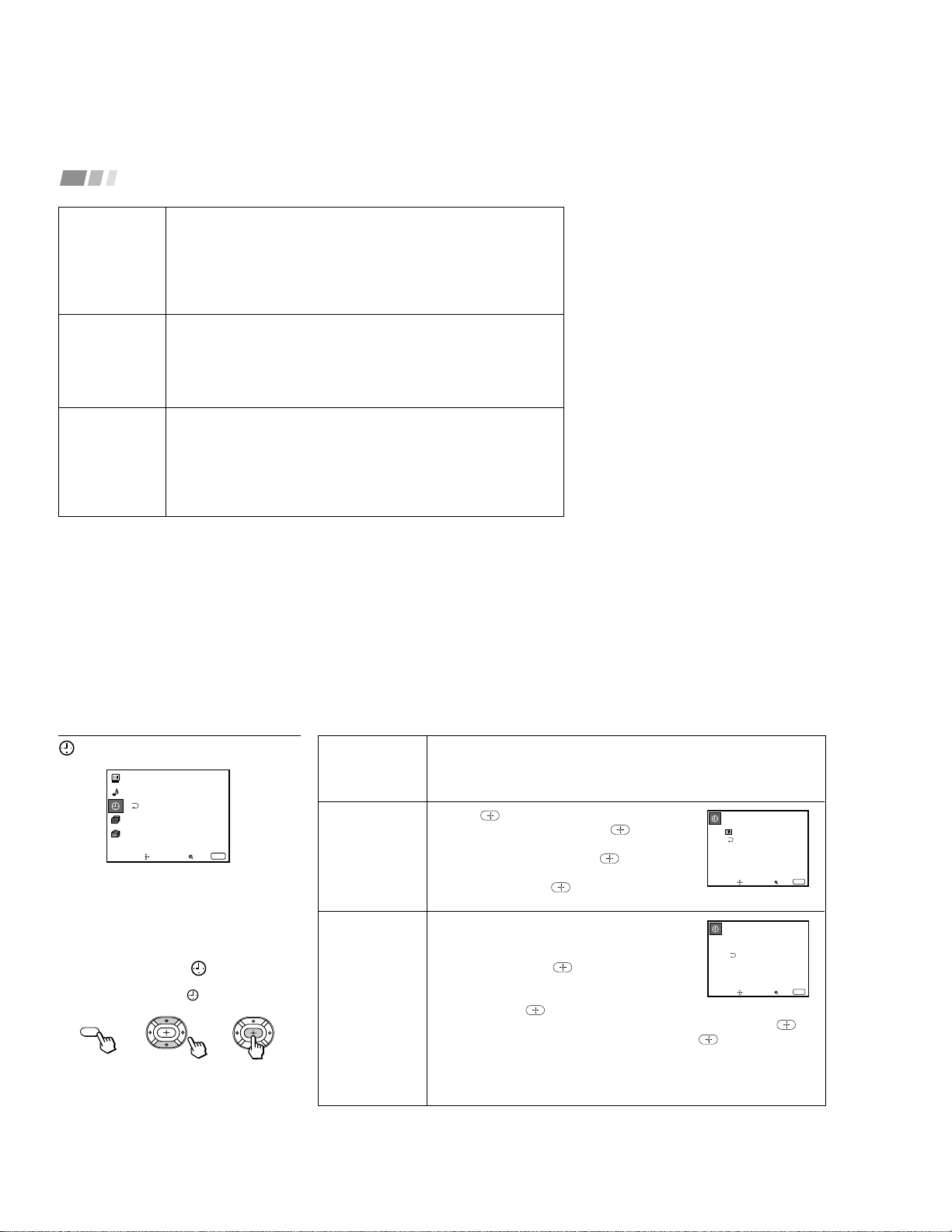
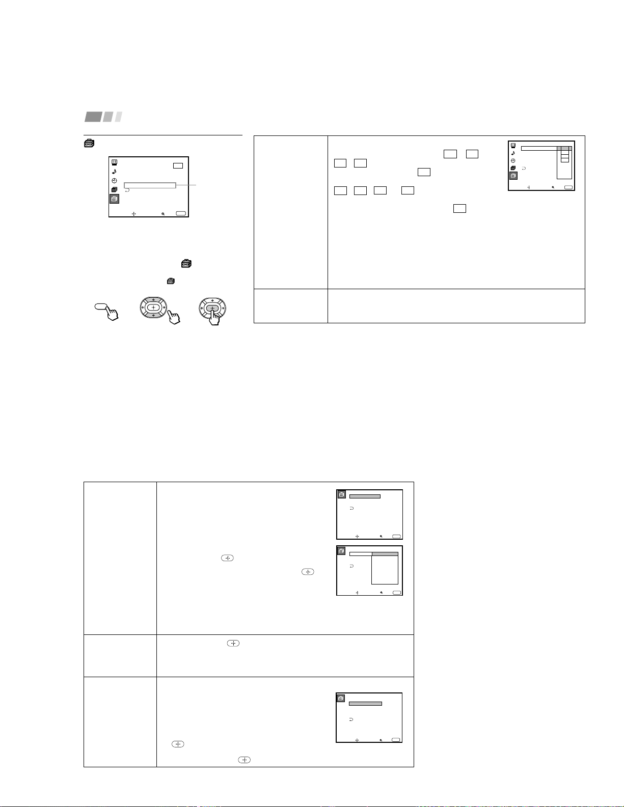
Hora de verano
Automatically
adjusts the time.
Fijar hora actual
Necessary for the
Timer.
Cronómetro
Wake up or
scheduled viewing.
Using the Reloj Menu
After setting the clock you can use the timer
to turn the projection TV on and off.
For detailed information on using the remote
control to modify menu settings, refer to
“Learning Menu Selection” on page 19.
To select the Reloj menu:
Display
/
Highlight
/
Select
Tip
z
• Set daylight saving time before setting the clock.
Any loss of power will cause these settings to be
erased.
• To maintain clock and timer settiongs, MAIN
POWER must be leht in ON position. (KP-
43T75A/53SV75A only)
Spring: Select Sí to compensate for Daylight Saving Time.
The current time automatically moves ahead one hour.
Fall: Select No at the end of Daylight Saving Time.
The current time moves back one hour.
1 Press
, then press V or v until the current day
(Sun-Sat) is displayed, and press
.
2 Press V or v until the current hour (1-12) and
AM/PM is displayed, and press
.
3 Press V or v until the current minute (00-59) is
displayed, and press
.
The clock has now started. Press MENU to exit.
1 Press V or v until the desired day or range of days
(Every Sun-Sat, Every Mon-Fri, Sunday, Monday, ...
Saturday, Every Sunday, ... Every Saturday) is
displayed, and press
.
2 Press V or v until the time (hours and minutes) that
you want the projection TV to remain on is displayed,
and then press
.
3 Press V or v to set the time duration (maximum of 6 hours) and press
.
4 Press V or v to select the desired channel and press
.
The timer is now set. The TIMER/STAND BY indicator on your projection TV
will be lit (For KP-43T75A/53SV75A, the indicator will be orange).
Press MENU to exit. To cancel your timer setting, press RESET while in the
Cronómetro window. Performing Auto programación will erase all “Reloj” settings.
MENU
Reloj
Hora de verano: Sí
Fijar hora actual
Cronó metro
----- : -AM-
ch
Mover Seleccionar
Salir
MENU
Fijar hora actual
–––
––: – AM–
Mover Seleccionar
Salir
MENU
Cronó metro
––––––
––: –– AM
–
hch
–––
Dom
12:00AM
Mover Seleccionar
Salir
MENU
– 19 –
24
Adjusting Your SET UP (menus) (continued)
ch
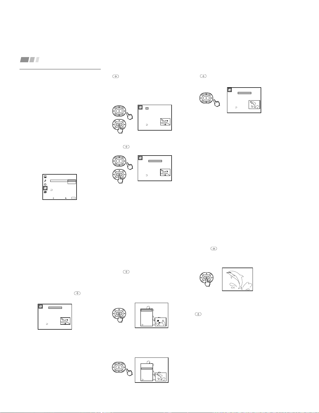
Using the Ajustes de canal
Menu
For detailed information on using the remote
control to modify menu settings, refer to
“Learning Menu Selection” on page 19.
To select the Ajustes de canal
ch
menu:
Display
/
Highlight
ch
/
Select
Nombre del
canal
Easy recognition
of the channel
you are watching
Canal favorito
User’s favorite
channels
You can add a caption for up to 32 channels of VHF/
UHF input.
With the “Nombre del canal” window open:
1 Press
and then press V or v to select the desired
channel. You can view the channel that is selected
with the Nombre del canal menu in the sub screen.
2 Press .
3 Press V or v to display the first letter or number of the
caption and press
to select it.
Repeat until up to five digits are selected.
4 Press
.
To erase a caption, press RESET.
The Canal favorito feature enables easy access to the eight channels that you
preset (or the last channel that you were watching).
(for details on how to set up this feature, see “Setting and Selecting Canal favorito”
on page 26)
MENU
Ajuste de canal
Canal favorito :Auto
Canal omitir/agregar
Nombre del canal
Auto programació n
Cable: Sí
ch
Mover Seleccionar
Salir
MENU
Nombre del canal
Nombre: – ––––
Canal: –––
Mover Seleccionar
Salir
MENU
25
Canal omitir/
agregar
Skips unnecessary
channels.
Auto
programación
Automatic
channel presetting
Cable
Cable system
setting
After AUTO SET UP, you can erase unnecessary
channels from the channel preset memory.
With the “Canal omitir/agregar” window open:
1 Press V or v to select the desired channel. You can
view the channel that is selected with the Canal
omitir/agregar menu in the sub screen. You can also
use CH +/– or 0–9 and ENTER buttons.
2 Press
.
3 Press V or v to select omitir, and press
.
The selected channel will be erased.
If you want to re-enter the skipped channel, follow the steps above and select
agregar.
Select Sí to signal the projection TV to automatically program all receivable
channels. When all the receivable channels are stored, the lowest numbered
channel is displayed.
Select No to cancel Auto programación.
Select Sí if your projection TV is connected to a cable system.
Select No if your projection TV is connected to an antenna.
Canal omitir/agregar
Seleccione el canal
2:
3:
4:
5:
6:
7:
8:
1:
9:
omitir
omitir
agregar
agregar
agregar
agregar
agregar
agregar
agregar
ch
Mover Seleccionar
Salir
MENU
– 20 –
26
Adjusting Your SET UP (menus) (continued)
2
Press V or v to select “Manual” and press
.
The Canal favorito menu will appear. If
you set Nombre del canal names, they
will also be displayed. (see “Nombre del
canal” on page 24)
3
Press V or v to select a position (1–8), and
press
.
Setting and Selecting Canal
favorito
The Canal favorito feature of your projection
TV enables easy access to the eight channels
that you preset (or the last channel that you
were watching).
Your Canal favorito options can be set
automatically or manually.
The factory setting for “Canal favorito” is
“Auto.”
When “Canal favorito” is set to “Auto,” the
last eight channels selected with the 0–9
buttons will be set as Canal favorito options.
If you want to input your own selections as
Canal favorito settings, set to “Manual.”
Setting Canal favorito manually
1
Select “Canal favorito” from the Ajuste
de canal menu. (see page 24)
Ajuste de canal
Canal omitir/agregar
Nombre del canal
Auto programació n
Cable: Sí
Manual
Canal favorito: Auto
ch
Mover Seleccionar
Salir
MENU
Canal favorito
Seleccione la posición
2.
3.
4.
5.
6.
7.
8.
1.
2
10
20
30
40
50
100
1
SPTN
CNN
ch
Canal favorito
Seleccione el canal
2.
3.
4.
5.
6.
7.
8.
1.
2
10
20
30
40
50
100
1
SPTN
CNN
ch
4
Press V or v to select a channel and press
.
You have now selected a favorite channel.
5
Use V and v to program other favorite
channels. (Follow steps 3 and 4.)
6
Press MENU when you have finished.
Your favorite channels are now ready for
use.
Canal favorito
Seleccione el canal
2.
3.
4.
5.
6.
7.
8.
1.
8
10
20
30
40
50
100
1
SPTN
CNN
ch
27
3
Press to select the channel.
The selected channel will be displayed for
normal viewing.
To cancel the favorite channel menu before
selecting a channel, press V or v to select
“Salir” at the bottom of the menu and press
.
Changing Canal favorito choices
You have the option of returning to the Canal
favorito screen to adjust any of your favorite
channel choices.
Simply proceed as described in “Setting
Canal favorito manually” (skip step 2 if
“Manual” is already selected).
When you reach step 3, select the position
you want to change and press . Press V or
v to select a new channel.
Press MENU when you are done.
Using Canal favorito
You can use the Canal favorito feature to
directly select the channel you want to
watch.
1
Press once.
The favorite channel menu and a window
picture will be superimposed over the
current channel. The window picture
displays the channel selected from the
menu.
2
Press V or v to select the channel that you
wish to view from the menu.
The picture of the selected channel will be
displayed in the window picture.
2.
3.
4.
5.
6.
7.
8.
1.
2
10
20
30
40
50
100
6
SPTN
ch
Canal favorito
Seleccione el canal
2
10
20
30
40
50
100
Salir
1 CNN
SPTN
2
10
20
30
40
50
100
Salir
1 CNN
SPTN
– 21 –
28
Adjusting Your SET UP (menus) (continued)
Caption Vision
Television closed
caption display
Lenguaje
Preferred language
Some programs are broadcast with Caption Vision.
To display “Caption Vision,” select CC 1, CC 2,
CC 3, CC 4, TEXT1, TEXT2, TEXT3 or TEXT4 from
the menu. Then press the CC button until “Caption
Vision” is displayed.
CC 1, CC 2, CC 3 or CC 4 displays a printed
version of the dialogue or sound effects of a
program. (The mode should be set to CC 1 for most
programs.) TEXT1, TEXT2, TEXT3, or TEXT4
displays network/station information presented using
either half or the whole screen.
Notes:
• Poor reception of TV programs can cause errors in Caption Vision and XDS.
Captions may appear with a white box or other errors instead of the intended
text.
• XDS, Caption Vision, and the status display cannot be used at the same time.
Select from available languages to display all menus in your language of choice:
English, Español and Português for the KP-43T75A/53SV75A
English, Español and Français for the KP-43T75C/53SV75C/61SV75C
Using the Ajustes Menu
For detailed information on using the remote
control to modify menu settings, refer to
“Learning Menu Selection” on page 19.
To select the Ajustes menu:
Display
/
Highlight
/
Select
MENU
Ajustes
Caption Vision: CC1
Lenguaje: Españ ol
Etiqueta de video
Flash Focus: No
ch
Mover Seleccionar
Salir
MENU
Sistema de color
KP-43T75A/
53SV75A only
Sistema de color
Lenguaje:
Ajustes
Etiqueta de video
Flash Focus: No
Caption Vision
:
CC2
CC1
CC3
CC4
Text1
Text2
Text3
Text4
ch
MENU
Mover Seleccionar
Salir
29
Etiqueta de video
Easy recognition of
connected
equipment
(e.g. DVD, VHS,
etc.)
Flash Focus
Automatic
convergence
adjustment
Sistema de color
Select the TV
color system.
(KP-43T75A/
53SV75A only)
This feature allows you to label each input mode so
that you can easily identify the connected equipment
(e.g. you can label VIDEO 1 IN as VHS).
With the “Etiqueta de video” window open:
1 Press V or v to select the input mode you want to
label and press
.
2 Press V or v to select the label and press
.
Etiqueta de video Options:
VIDEO 1: VIDEO 1, VHS, 8mm, Beta, LD, DVD, AV RECEIVER, Omitir
VIDEO 2/3: VIDEO 2/VIDEO 3, VHS, 8mm, Beta, LD, DVD, Omitir
If you select “Omitir,” your projection TV will skip this connection when you scan
through video sources using the TV/VIDEO button.
Select Sí and press to start Flash Focus adjustment. When the adjustment
is completed, the cross pattern on the screen becomes white. (for details, see
page 13)
Select No to cancel Flash Focus.
This feature allows you to set the TV color system for each input mode.
Normally set it to “Auto.”
If the picture does not appear clearly, set the color
system to “PAL-N” manually.
With the “Sistema de color” window open:
1 Press V or v to select the input mode and press
.
2 Press V or v to select the TV color system (Auto n PAL-M n PAL-N
n NTSC) and press
.
Etiqueta de video
VIDEO1
VIDEO2
VIDEO3
VIDEO1:
VIDEO2:
VIDEO3:
MENU
Mover Seleccionar
Salir
MENU
Mover Seleccionar
Salir
Etiqueta de video
VIDEO1:
VIDEO2:
VIDEO3:
Video1
VHS
8mm
Beta
LD
DVD
AV RECEIVER
Omitir
Sistema de color
Auto
Auto
Auto
Auto
TV:
VIDEO1:
VIDEO2:
VIDEO3:
Mover Seleccionar
Salir
MENU
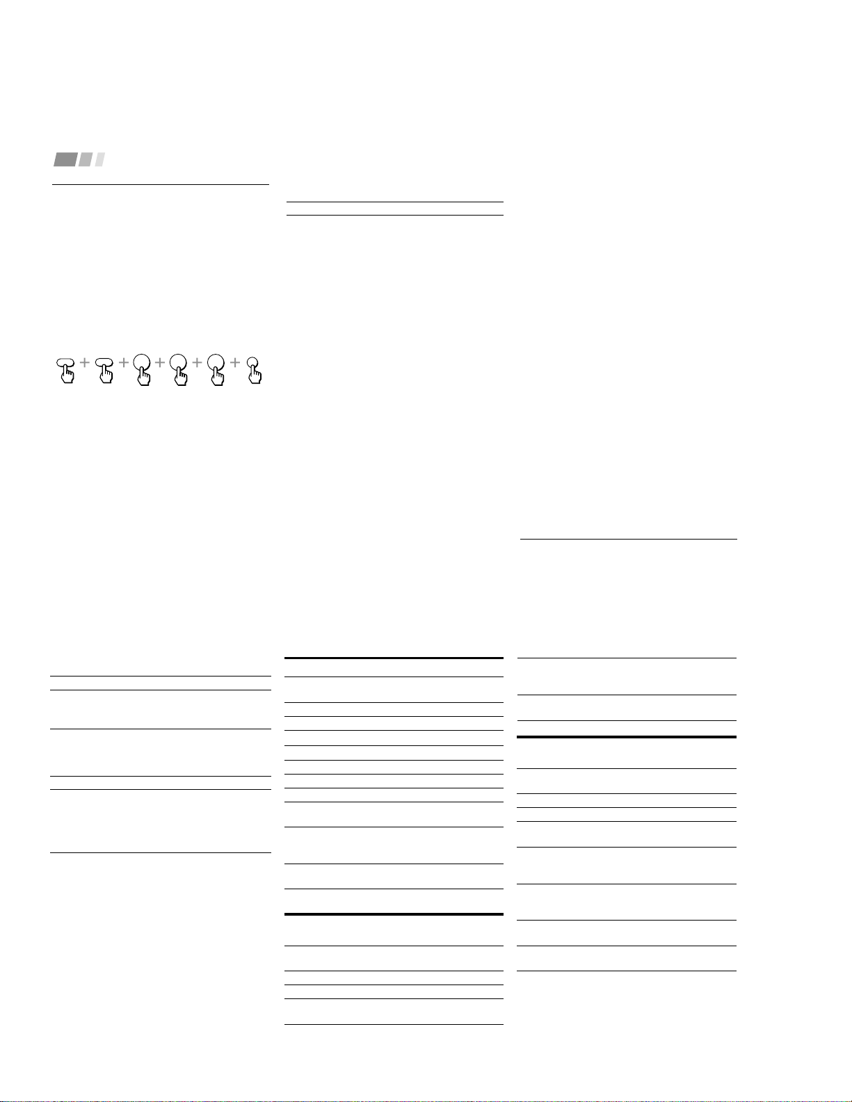
– 22 –
30
Adjusting Your SET UP (menus) (continued)
VCR manufacturer code numbers
Manufacturer Code
Sony (VHS VCR) 301
Sony (8mm VCR) 302
Sony (Beta, ED Beta, VCRs) 303
Aiwa 338
Admiral (M. Ward) 327
Audio Dynamic 314, 337
Bell & Howell (M. Ward) 330
Broksonic 319, 317
Canon 309, 308
Citizen 332
Craig 302, 332
Curtis Mathis 304, 338, 309
Daewoo 341, 312, 309
DBX 314, 336, 337
Dimensia 304
Emerson 319, 320, 316, 317, 318, 341
Fisher 330, 335
Funai 338
General Electric 329, 304, 309
Go Video 340, 339, 322
Goldstar 332
Hitachi 306, 304, 305, 338
Instant Replay 309, 308
JC Penney 309, 305, 304, 330, 314, 336, 337
JVC 314, 336, 337
Kenwood 314, 336, 332, 337
LXI (Sears) 332, 305, 330, 335, 338
Magnavox 308, 309, 310
Marantz 314, 336, 337
Marta 332
Memorex 309, 335
Operating Video Equipment
Setting the Manufacturer's
Code
You can use the supplied remote control to
operate Sony or non-Sony video equipment
that has an infrared sensor.
Press CODE SET, DVD/VTR (FUNCTION),
and the 0-9 buttons to enter the
manufacturer’s code number (see the
following chart), then press ENTER.
For example, to operate a Sony 8mm VCR:
If the remote control doesn’t work
• See the tips on page 32.
Minolta 305, 304
Mitsubishi/MGA 323, 324, 325, 326
Multitech 325, 338, 321
NEC 314, 336, 337
Olympic 309, 308
Optimus 327
Panasonic 308, 309, 306, 307
Pentax 305, 304
Philco 308, 309
Philips 308, 309, 310
Pioneer 308
Quasar 308, 309, 306
RCA/PROSCAN 304, 305, 308, 309, 311,
329, 312, 313, 310
Realistic 309, 330, 328, 335, 324, 338
Sansui 314
Samsung 322, 313, 321
Sanyo 330, 335
Scott 312, 313, 321, 335, 323, 324, 325, 326
Sharp 327, 328
Signature 2000 (M. Ward) 338, 327
Sylvania 308, 309, 338, 310
Symphonic 338
SV2000 338
Tashiro 332
Tatung 314, 336, 337
Teac 314, 336, 338, 337
Technics 309, 308
Teknica 338
Toshiba 312, 311
Wards 327, 328, 335, 331, 332
Yamaha 330, 314, 336, 337
Zenith 331
2
3
0
CODE SET
ENTER
DVD/VTR
FUNCTION
31
MDP manufacturer code numbers
Manufacturer Code
Sony 701
Panasonic 704, 710
Mistubishi 702
DVD Player manufacturer code
numbers
Manufacturer Code
Sony 751
Panasonic 753
Pioneer 752
RCA 755
Toshiba 754
Tips
z
• In some rare cases, you may not be able to operate
your non-Sony video equipment with the supplied
remote control. In this case, please use the
equipment's own remote control.
• When you remove the batteries, the code number may
revert to the factory setting.
To operate video equipment
1
Press DVD/VTR (FUNCTION).
2
Use the VCR/DVD/MDP operation
buttons indicated in the following tables.
Operating an MDP using the remote
control
To turn On/Off
To play
To stop
To pause
Operating a VCR using the remote control
To turn On/Off
To select a channel
To change channels
To record
To play
To stop
To fast forward
To rewind the tape
To pause
To search the
picture forward or
backward
To change input
mode
Press DVD/VTR (POWER).
[Green Button]
Press the 0 – 9 buttons.
Press CH +/–.
Press ( while pressing r.
Press (.
Press p.
Press ).
Press 0.
Press P. Press again to
resume normal playback.
Press ) or 0 during
playback. Release to
resume normal playback.
Press TV/VTR.
Press DVD/VTR (POWER).
[Green Button]
Press (.
Press p.
Press P. Press again to
resume normal playback.
Operating a DVD Player using the remote
control
To turn On/Off
To play
To stop
To pause
To step through
different tracks of
an audio disc
To step through
different chapters
of a video disc
To select tracks
directly
To display the
menu (Set up)
Press DVD/VTR (POWER).
[Green Button]
Press (.
Press p.
Press P. Press again to
resume normal playback.
Press ) to step forward or
0 to step backward.
Press CH + to step forward
or CH – to step backward.
Press 0-9 buttons.
Press MENU.
Press ) or 0 during
playback. Release to resume
normal playback.
Press CH +/–.
To search the picture
forward or backward
To search a chapter
forward or backward
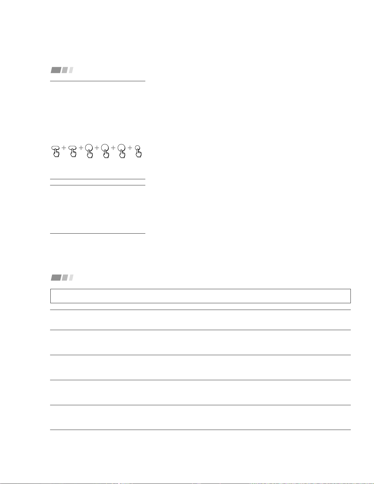
– 23 –
32
Adjusting Your SET UP (menus) (continued)
Setting the Manufacturer's
Code
You can program the supplied remote
control to operate a cable box.
Press CODE SET, SAT/CABLE
(FUNCTION)*, and the 0-9 buttons to enter
the manufacturer’s code number (see the
following chart), then press ENTER.
For example, to operate a Pioneer cable box:
Manufacturer code numbers
(cable box)
Manufacturer
Hamlin/Regal
Jerrold/G.I
Oak
Panasonic
Pioneer
Scientific Atlanta
Tocom
Zenith
Code
222, 223, 224, 225, 226
201, 202, 203, 204, 205,
222, 206, 207, 208, 218
227, 228, 229
219, 220, 221
214, 215
209, 210, 211
216, 217
212, 213
Operating a Cable Box
4
2
1
CODE SET
ENTER
SAT/CABLE
FUNCTION
Tips z
• If more than one code number is listed, try entering
them one by one until you come to the correct code
for your equipment.
• If you enter a new code number, the code number
you previously entered at that setting is erased.
• In some rare cases, you may not be able to operate
your equipment with the supplied remote control. In
this case, use the equipment’s own remote control
unit.
• Whenever you remove the batteries — to replace
them, for example — if too much time is taken, the
code numbers may revert to the factory setting and
must be reset.
To operate the cable box
1
Press SAT/CABLE (POWER)* [Green
Button] to turn on/off the cable box.
2
Press SAT/CABLE (FUNCTION)*.
3
For other operations, refer to the
operating instructions that come with the
equipment.
* The SAT/CABLE (POWER) and SAT/CABLE
(FUNCTION) buttons cannot operate a
satellite receiver (SAT) in Argentine and Chile
even if it is connected to the projection TV.
If the remote control doesn’t work
• Try repeating the set up procedures using
the other codes listed for your equipment.
To operate the projection TV
Press TV (FUNCTION). Then use the
projection TV control buttons to control the
projection TV.
33
The picture turns off and the
TIMER/STAND BY indicator on the
front panel flashes (self-diagnosis
function)
No picture (screen not lit), no
sound
Remote control does not
operate
Dark, poor or no picture
(screen lit), good sound
Good picture, no sound
Troubleshooting
• The projection TV is equipped with a self-diagnosis function. If there is a problem with your projection TV, the TIMER/STAND BY indicator on the front
panel will flash repeatedly. Counting the number of flashes helps you inform qualified Sony Authorized Service Center of the projection TV’s condition.
• Press POWER on the projection TV to turn it off, then inform qualified Sony Authorized Service Center of the number of flashes.
• Make sure the power cord is plugged in.
• Operate with the buttons on both the projection TV and the remote control.
• Check to see if the TV/VIDEO setting is correct: when watching TV, set to TV, and when watching video tapes, set to VIDEO 1, 2, or 3.
• Try another channel.
It could be station trouble.
• Perform AUTO SET UP again using the SET UP button to return to the factory preset condition. (see “To perform AUTO SET UP again” on page 13)
• Batteries could be weak. Replace the batteries.
• Press TV (FUNCTION) when operating your projection TV.
• Make sure the projection TV’s power cord is connected securely to the wall outlet.
• Locate the projection TV at least 3-4 feet away from fluorescent lights.
• Check the polarity of the batteries.
• Adjust “Contraste” in the Video menu. (see “Ajuste de imagen” on page 20)
• Adjust “Brillo” in the Video menu. (see “Ajuste de imagen” on page 20)
• Check antenna/cable connections.
• Perform AUTO SET UP again using the SET UP button to return to the factory preset condition. (see “To perform AUTO SET UP again” on page 13)
• Adjust the convergence again using the FLASH FOCUS button. (see “Adjusting the Convergence Automatically (FLASH FOCUS)” on page 13)
• Press MUTING so that “Suprimir el sonido” disappears from the screen. (see “MUTING” on page 14)
• Check the MTS/SAP setting in the Audio menu. (see “MTS/SAP” on page 21)
• Make sure “Parlantes” is set to “Sí” in the Audio menu. (see “Parlantes” on page 22)
• Perform AUTO SET UP again using the SET UP button to return to the factory preset condition. (see “To perform AUTO SET UP again” on page 13)
• Set the appropriate TV color system in the Ajustes menu. (see “Sistema de color” on page 29)
If, after reading the following instructions, you have additional questions related to the use of your Sony projection TV, please contact your nearest Sony
Authorized Service Center.
(continued)

– 24 –
34
Cannot receive upper channels
(UHF) when using an antenna
No color
Only snow and noise appear on
the screen
Dotted lines or stripes
TV is fixed to one channel
Double images or ghosts
Cannot operate the menu
Cannot receive any channels
when using cable TV
Cannot gain enough volume when
using a cable box
Canal favorito does not display
your choices
Some video sources do not
appear when you press TV/VIDEO
Recording through MONITOR OUT
does not function properly when
recording in PIP mode
Cannot play shooting games
• Make sure “Cable” is “No” in the Ajuste de canal menu. (see “Cable” on page 25)
• Use “Auto programación” to add receivable channels that are not presently in the TV’s memory. (see “Auto programación” on page 25)
• Adjust “Color” in the Video menu. (see “Ajuste de imagen” on page 20)
• Black and white programs cannot be seen in color.
• Perform AUTO SET UP again using the SET UP button to return to the factory preset condition. (see “To perform AUTO SET UP again” on page 13)
• Set the appropriate TV color system in the Ajustes menu. (see “Sistema de color” on page 29)
• Check the “Cable” setting in the Ajuste de canal menu. (see “Cable” on page 25)
• Check the antenna/cable connections.
• Make sure the channel is broadcasting programs.
• Press ANT to change the input mode. (see “ANT” on page 16)
• Set the appropriate TV color system in the Ajustes menu. (see “Sistema de color” on page 29)
• Adjust the antenna.
• Keep the projection TV away from noise sources such as cars, neon signs or hair-dryers.
• Use “Auto programación” to add receivable channels that are not presently in TV’s memory. (see “Auto programación” on page 25)
• Use a highly directional outdoor antenna or a cable (when the problem is caused by reflections from nearby mountains or tall buildings).
• If the item you want to choose appears in gray, you cannot select it.
• Press the projection TV’s power button off and on again.
• Make sure “Cable” is “Sí” in the Ajuste de canal menu. (see “Cable” on page 25)
• Use “Auto programación” to add receivable channels that are not presently in the TV’s memory. (see “Auto programación” on page 25)
• Increase the volume at the cable box. Then press TV (FUNCTION) and adjust the projection TV’s volume.
• Verify that “Canal favorito” is set to “Manual” in the Ajuste de canal menu. (see “Setting Canal favorito manually” on page 26)
• Ensure that “Etiqueta de video” is not set to “Omitir.” (see “Etiqueta de video” on page 29)
• MONITOR OUT will not record both images in PIP. Only the main picture will be recorded.
• If you are recording the main picture and you switch to the sound of the sub picture using the AUDIO button, the main picture will be recorded with sound
from the other program.
• Some shooting games which involve pointing a light beam at the TV screen with an electronic gun or rifle cannot be used with this projection TV. For
details, see the instruction manual supplied with the video game software.
Troubleshooting (continued)
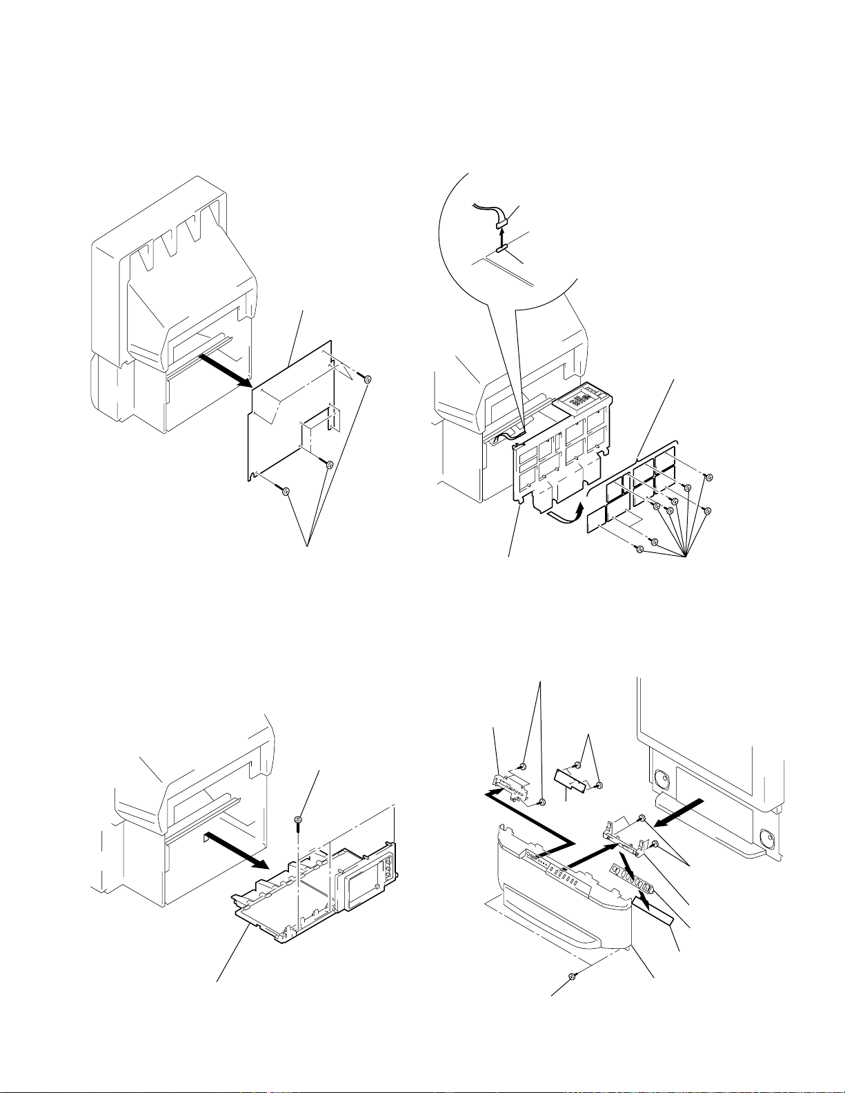
– 25 –
KP-43T75C/53SV75C/61SV75C
RM-Y906RM-Y906RM-Y906
SECTION 2
DISASSEMBLY
2-1. REAR BOARD REMOVAL 2-3. SERVICE POSITION
2-2. CHASSIS ASSY REMOVAL
2-4. HA BOARD AND HB BOARD REMOVAL
(EXCEPT KP-43T75C)
2 Rear board
1 Nine screws (Except KP-43T75C)
Eight screws (KP-43T75C)
(Screw(4x20), tapping)
1 Three screws
(Screw(4x20),tapping)
2 Chassis assy
1 Disconnect CN203
on A board.
From CG board CN1304.
(The extension cable is not
supplied because of the
countermeasure for radiation.)
G board
CN203
A board
2 Covers
Cut them off with a plier or the like
from chassis assembly in case of
checking printed circuit boards.
After checking, turn over the covers
and secure them with screws.
Screws
(+BVTP3x12)
Chassis assembly
8 Three screws
(+BVTP 3x12)
6 Four screws
(+BVTP 4x12)
2 Two screws
(+BVTP 4x12)
1 Two screws
(Screws (4x20), tapping)
9 HB board
7 HB bracket
Speaker grille assy
5 HA board
3 HA bracket
4 Multi button
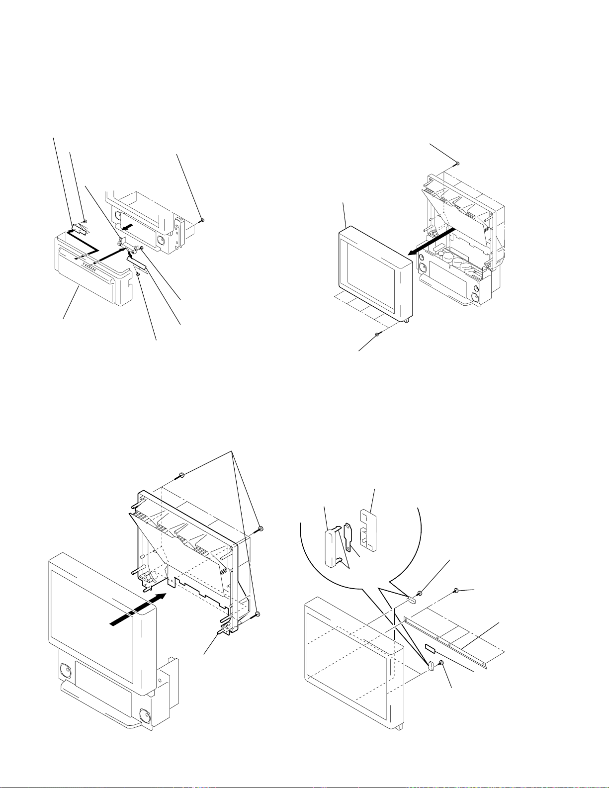
– 26 –
KP-43T75C/53SV75C/61SV75C
RM-Y906RM-Y906
RM-Y906
2-6. MIRROR COVER REMOVAL
2-7. BEZNET ASSY REMOVAL
2-8. HC BOARD AND S BOARD REMOVAL
2-5. HA AND HB BOARD REMOVAL
(KP-43T75C)
3 HC board
2 L screen holder
6 Clows
7 S board
Sensor
bracket (B)
4 Two screws
(+BVTP 4x12)
1 Two screws
(+BVTP 4x12)
5 Two screws
(+BVTP 4x12)
Sensor
bracket (A)
7 Three screws
(+BVTP 3x12)
3 Four screws
(+BVTP 3x12)
5 Three screws
(+BVTP 3x12)
1 Four screws
(Screws (4x20), tapping)
8 HB board
Panel ASSY, Control
6 HA board
4 HA bracket
2
1 Three screws
(KP-43T75C)
Five screws
(KP-53SV75C/61SV75C)
(Screws (4x20), tapping)
2 Eleven screws (KP-43T75C)
Fifteen screws (KP-53SV75C)
Fourteen screws (KP-61SV75C)
(Screws (4x20), tapping)
3 Beznet assy
1 Seventeen screws (KP-43T75C)
Nineteen screws (KP-53SV75C)
Twenty three screws (KP-61SV75C)
(Screw(4x20), tapping)
2 Mirror cover
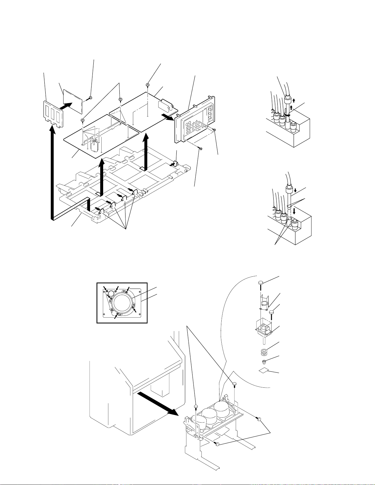
– 27 –
KP-43T75C/53SV75C/61SV75C
RM-Y906RM-Y906RM-Y906
2-9. A, G AND FA BOARDS REMOVAL 2-11. HIGH-VOLTAGE CABLE INSTALLATION
AND REMOVAL
7 Two screws
(+BVTP 3x12)
0 Screw
(+BVTP 3x12)
4 Eight screws
(+BVTP 3x12)
6 G board
!™ FA board
9 A board
3 Terminal board
8 Claw
5 Claws
Main bracket
!¡ FA board bracket
1 Two screws
(Screws (4x20), tapping)
2 Seven screws
(+BVTP 3x12)
2-10. PICTURE TUBE REMOVAL
4 Four screws
(Screw(4x20), tapping)
9 Four screws
(+BVTP 4x12)
0 Picture tube
Picture tube
8 Diflection yoke
2 Four screws
(Screw(4x20), tapping)
3
1 Four screws
(Screw(4x20), tapping)
7 Neck assy
6 CR board
5 Lens
Lens
CAUTION: Removing the arrow-marked
screws is strictly prohibited.
If removed, it may cause liquid spill.
(1) Removal
1 Rubber cap
2 HV cable
turn 90°
1 HV cable
Gutter
Hook
(2) Installation
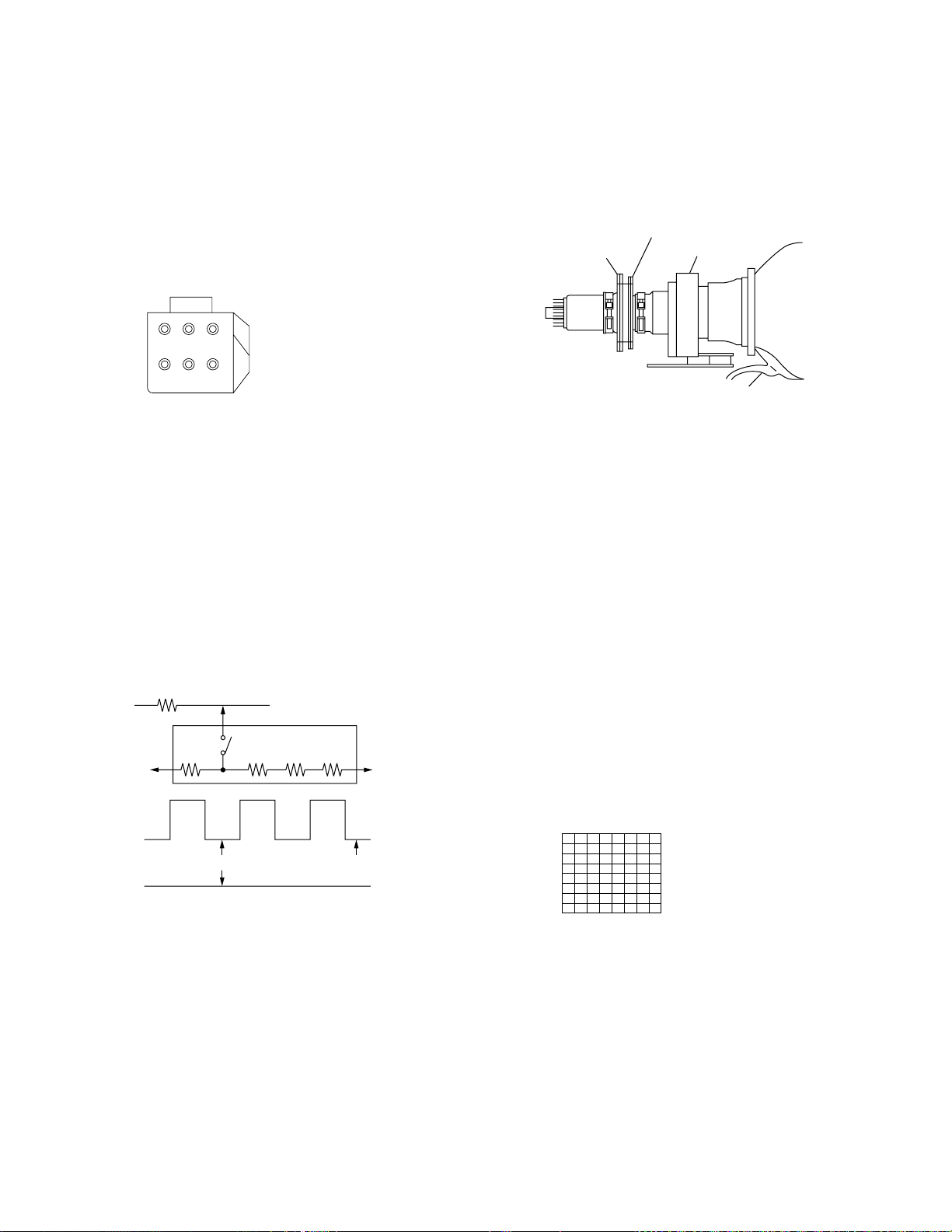
– 28 –
KP-43T75C/53SV75C/61SV75C
RM-Y906RM-Y906
RM-Y906
3-1. SCREEN VOLTAGE ADJUSTMENT
(COARSE ADJUSTMENT)
1. Receive the Monoscope signal.
2. Set 50% BRIGHTNESS and minimum PICTURE.
3. Turn the red VR on the FOCUS block all the way to the left
and then gradually turn it to the right until the point where you
can see the retrace line.
4. Next gradually turn it to the left to the position where the
retrace line disappears.
R G B
SCREEN
R G B
FOCUS
FOCUS block
Fig. 3-1
SECTION 3
SET-UP ADJUSTMENTS
175 ± 2V
G2 JIG
200V GND
3.3k 5.6k 5.6k 5.6k
SW
K
GND
pedestal level
Fig. 3-2
3-2. SCREEN (G2) ADJUSTMENT
(FINE ADJUSTMENT)
Fine Mode is recommended to set screen controls to their optimal
condition. It is necessary to build the simple jig, illustrated below,
using 3-watt resistors. Please note, that if the proper voltage is not
obtained with their listed values, resistors, then please increase or
decrease one of the values in the resistor network to obtain the
correct voltage.
1. Select VIDEO1 mode without signals.
2. Connect G2 JIG.
3. SW on JIG.
4. Connect an oscilloscope to the TP701(KR), TP732(KG) and
TP761(KB) of CR board, CG board and CB board.
5. Adjust R, G and B screen voltage to 168-172V with screen
VR on the Focus block.
3-4. FOCUS LENS ADJUSTMENT
In this adjustment, use the remote commander in the
service mode.
For details of the usage of the service mode and the remote
commander, please refer the item 3-9. ELECTRICAL
ADJUSTMENT BY REMOTE COMMANDER.
1. Loosen the lens screw.
2. Set to the service mode.
3. Receive the all-white signal.
4. Cover the both red and blue picture lenses with the lens caps
to show only the green color.
5. Set to PJE, and press 6 to display the test signal (crosshatch)“
on the screen.
6. Turn the green lens to adjust to the optimum focus point with
the test signal.
7. Tighten the lens screw.
8. Cover the both green and blue picture lenses with the lens caps
to show only the red color.
9. Set to PJE, and press 6 to display the test signal (crosshatch)“
on the screen.
10. Adjust red CRT lens just the same as green.
11. Cover the both green and red picture lenses with the lens caps
to show only the blue color.
12. Set to PJE, and press 6 to display the test signal (crosshatch)“
on the screen.
13. Adjust blue CRT lens just the same as green.
14. After adjusting the items 3-5. Focus VR Adjustment, 3-6. 2-
Pole Magnet Adjustment and 3-7. 4-Pole Magnet Adjustment,
adjust again to the optimum focus point.
*: Every time you press 6, the test signal changes to
“crosshatch+video signal” - “dots+video signal” -
“crosshach(black)” - “dots(black)” - off.
Note: Instead of items 4, 8 and 11, you can cut off the unnecessary
color beams by controlling the service mode VPNT 28 RON,
29 GON, and 30 BON.
Fig. 3-4
Test signal
3-3. DEFLECTION YOKE TILT ADJUSTMENT
1. Receive the Monoscope signal.
2. Set in service mode.
3. Cover the both red and blue picture lenses with the lens caps
to show only the green color.
4. Loosen the deflection yoke set screw and align the tilt of the
Deflection Yoke so that the bars at the center of the
monoscope pattern are horizontal.
5. After aligning the deflection yoke, fasten it securely to the
funnel-shaped portion (neck) of the CRT.
6. The tilt of the deflection yoke for red is aligned in the mode
Cover the both green and blue picture lenses with the lens caps
and the tilt of the deflection yoke for blue is aligned with in
Fig. 3-3
2-pole magnet
4-pole magnet
Deflection yoke
Anode cap
the mode Cover the both green and red picture lenses with the
lens caps is aligned the same as was done for green.
Note: Instead of items 3 and 6, you can cut off the unnecessary
color beams by controlling the service mode VPNT 28 RON,
29 GON, and 30 BON.
Loading...