


KP-48V75
Operating Instructions
Manual de instrucciones
Color Rear Video
Pr ojector
© 1998 by Sony Corporation
3-862-729-11 (1)
EN
ES
KP-48V75
KP-53V75
KP-53V75C
KP-61V75
IMPORTANT SAFETY INFORMATION:
Please read the important safety information on page 2
-EN
.
INFORMACION IMPORTANTE SOBRE SEGURIDAD:
Lea la información importante sobre seguridad de la página 2
-ES
.
CONSIGNES DE SECURITE IMPORTANTES:
Veuillez lire les informations concernant la sécurité à la page 2
-EN
.
2
-EN
WARNING
To prevent fire or shock hazard, do not
expose the unit to rain or moisture.
CAUTION
RISK OF ELECTRIC SHOCK
DO NOT OPEN
ATTENTION
RISQUE DE CHOC ELECTRIQUE,
NE PAS OUVRIR
PRECAUCION
RIESGO DE CHOQUE ELECTRICO
NO ADRIR
CAUTION : TO REDUCE THE RISK OF ELECTRIC SHOCK,
DO NOT REMOVE COVER
(
OR BACK
)
.
NO USER-SERVICEABLE PARTS INSIDE.
REFER SERVICING TO QUALIFIED SERVICE PERSONNEL.
This symbol is intended to alert the user to the
presence of uninsulated “dangerous voltage”
within the product’s enclosure that may be of
sufficient magnitude to constitute a risk of
electric shock to persons.
This symbol is intended to alert the user to the
presence of important operating and
maintenance (servicing) instructions in the
literature accompanying the appliance.
CAUTION
To prevent electric shock, do not use this polarized AC plug
with an extension cord, receptacle or other outlet unless the
blades can be fully inserted to prevent blade exposure.
CAUTION
When using TV games, computers, and similar products with
your projection TV, keep the brightness and contrast
functions at low settings. If a fixed (non-moving) pattern is
left on the screen for long periods of time at a high brightness
or contrast setting, the image can be permanently imprinted
onto the screen. These types of imprints are not covered by
your warranty because they are the result of misuse.
Note on Caption Vision
This television receiver provides display of television closed
captioning in accordance with §15.119 of the FCC rules.
Note on CATV system installer
This reminder is provided to call the CATV system installer’s
attention to Article 820-40 of the NEC that provides
guidelines for proper grounding and, in particular, specifies
that the cable ground shall be connected to the grounding
system of the building, as close to the point of cable entry as
practical.
Use of this television receiver for other than private viewing
of programs broadcast on UHF or VHF or transmitted by
cable companies for the use of the general public may require
authorization from the broadcaster, cable company and/or
program owner.
Note on convergence adjustment
Before you use your projection TV, make sure to adjust
convergence. For the procedure, see page 21.
NOTIFICATION
This equipment has been tested and found to comply with
the limits for a Class B digital device pursuant to Part 15 of
the FCC Rules. These limits are designed to provide
reasonable protection against harmful interference in a
residential installation. This equipment generates, uses, and
can radiate radio frequency energy and, if not installed and
used in accordance with the instructions, may cause harmful
inteference with radio communications. However, there is no
guarantee that interference will not occur in a particular
installation. If this equipment does cause harmful
interference to radio or television reception, which can be
determined by turning the equipment off and on, the user is
encouraged to try to correct the interference by one or more
of the following measures:
– Reorient or relocate the receiving antennas
– Increase the separation between the equipment and
receiver.
– Connect the equipment into an outlet on a circuit different
from that to which the receiver is connected.
– Consult the dealer or an experienced radio/TV technician
for help.
You are cautioned that any changes or modifications not
expressly approved in this manual could void your
authority to operate this equipment.
This document is for the remote control RM-Y903.
MODELS: KP-48V75/53V75/53V75C/61V75.
Please keep this notice with the instruction manual.
NO ABRIR
As an ENERGY STAR Partner, Sony
Corporation has determined that this
product meets the ENERGY STAR
guidelines for energy efficiency.
ATTENTION
Pour prévenir les chocs électriques, ne pas utiliser cette fiche
polarisée avec un prolongateur, une prise de courant ou une
autre sortie de courant, sauf si les lames peuvent être inserées
à fond sans en laisser aucune partie à decouvert.

3
-EN
EN
Table of contents
4 Welcome!
4 Precautions
Getting Started
5 Step 1: Installing the projection TV
6 Step 2: Hookup
20 Step 3: Setting up the remote control
21 Step 4: Setting up the projection TV automatically
(AUTO SET UP)
25 Changing the menu language
Operations
26 Watching the TV
28 Watching two programs at one time — PIP/P&P
(Twin View™)/CH INDEX
30 Freezing the picture (FREEZE)
30 Adjusting the picture (VIDEO)
31 Adjusting the color temperature (TRINITONE)
32 Selecting the video mode (VIDEO)
32 Adjusting the sound (AUDIO)
33 Using audio effect (EFFECT)
34 Selecting stereo or bilingual programs (MTS)
35 Setting the speaker switch (SPEAKER)
36 Setting audio out (AUDIO OUT)
36 Setting daylight saving time (DAYLIGHT SAVING)
37 Setting the clock (CURRENT TIME SET)
37 Setting the timer to turn the projection TV on and
off (ON/OFF TIMER)
38 Customizing the channel names (CHANNEL CAPTION)
39 Blocking out a channel (CHANNEL BLOCK)
40 Setting your favorite channels (FAVORITE CHANNEL)
41 Setting video labels (VIDEO LABEL)
42 Setting Caption Vision (CAPTION VISION)
42 Operating video equipment
45 Operating a cable box or DBS receiver
Additional Information
46 Troubleshooting
47 Specifications
48 Index to parts and controls
50 Index
The captions in parentheses indicate menu names.
Owner’s Record
The model and serial numbers are located at the rear of the
projection TV. Record these numbers in the spaces
provided below. Refer to them whenever you call upon
your Sony dealer regarding this product.
Model No.
Serial No.

4
-EN
Welcome!
Thank you for purchasing the Sony Color Rear Video
Projection TV. Here are some of the features you will
enjoy with your projection TV:
• Two tuner Picture-in-Picture (PIP) that allows you
to watch another TV channel, video or cable image
as a window or left picture.
• FAVORITE CHANNEL that allows you to view and
choose from eight of your favorite programs.
• CH INDEX that allows you to view and choose
from twelve programs.
• SAVA SPEAKER option on the AUDIO menu that
lets you utilize the Sony SAVA series speaker
system’s surround sound and super woofer mode
when you connect it to the projection TV.
• S-Link
TM
that allows you to automatically change
the TV’s input mode, turn on the VCR, and play a
tape by just pressing the VCR’s play button. This
feature is a design unique to Sony.
• Y/CB/CR input connectors that allow you to
connect a DVD player with component video
output connectors.
About this manual
The instructions in this manual are for models KP-
48V75, KP-53V75, KP-53V75C, and KP-61V75. Before
you start reading this manual, please check your model
number, located at the rear of the projection TV.
Model KP-53V75 is used for illustration purposes in
this manual. Any differences in operation are clearly
indicated in the text, for example “KP-48V75 only”.
The differences in specifications are indicated in the
text.
Instructions in this manual are based on use of the
remote control. You can also use the controls on the
projection TV if they have the same name as those on
the remote control.
Precautions
This projection TV operates on extremely high voltage.
To prevent fire or electric shock, please follow the
precautions below.
Safety
• Operate the projection TV on 120 V AC (220 V AC for
KP-53V75C) only.
• One blade of the plug is wider than the other for safety
purposes and will fit into the power outlet only one
way. If you are unable to insert the plug fully into the
outlet, contact your dealer.
• Should any liquid or solid object fall into the cabinet,
unplug the projection TV and have it checked by
qualified personnel before operating it further.
• Unplug the projection TV from the wall outlet if you
are not going to use it for several days or more. To
disconnect the cord, pull it out by the plug. Never
pull the cord itself.
For details concerning safety precautions, see the supplied
leaflet “IMPORTANT SAFEGUARDS”.
Note on cleaning
Clean the cabinet of the projection TV with a dry soft
cloth. To remove dust from the screen, wipe it gently
with a soft cloth using vertical strokes only. Stubborn
stains may be removed with a cloth slightly dampened
with solution of mild soap and warm water. Never use
strong solvents such as thinner or benzine for cleaning.
If the picture becomes dark after using the projection TV
for a long period of time, it may be necessary to clean the
inside of the projection TV. Consult qualified service
personnel.
Installing
• To prevent internal heat build-up, do not block the
ventilation openings.
• Do not install the projection TV in a hot or humid
place, or in a place subject to excessive dust or
mechanical vibration.
• Avoid operating the projection TV at temperatures
below 5°C (41°F).
• If the projection TV is transported directly from a cold
to a warm location, or if the room temperature has
changed suddenly, the picture may be blurred or show
poor color. This is because moisture has condensed on
the mirror or lenses inside. If this happens, let the
moisture evaporate before using the projection TV.
• To obtain the best picture, do not expose the screen to
direct illumination or direct sunlight. It is
recommended to use spot lighting directed down from
the ceiling or to cover the windows that face the screen
with opaque drapery. It is desirable to install the
projection TV in a room where the floor and walls are
not of reflecting material. If necessary, cover them
with dark carpeting or wall paper.
Getting Started
5
-EN
EN
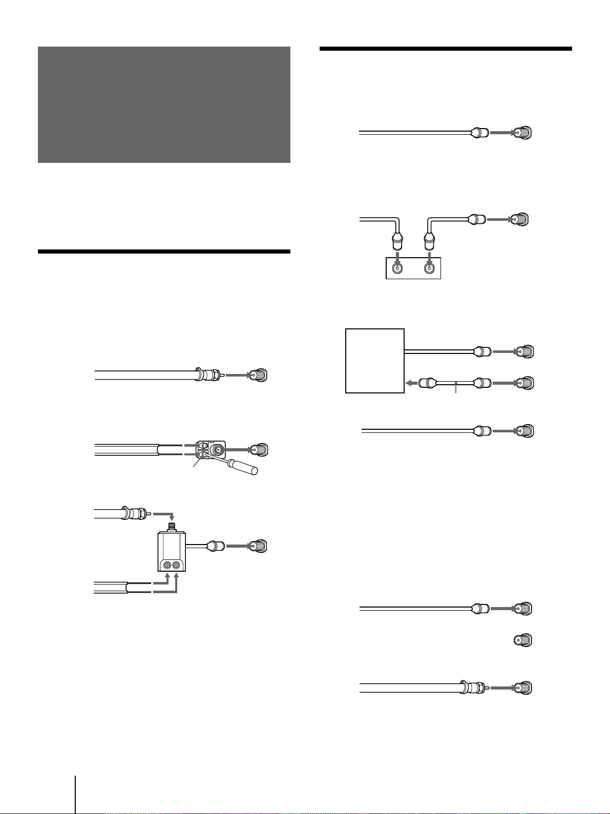
Carrying your projection TV
p KP-48V75/53V75/53V75C only
Be sure to grasp the areas indicated when carrying the
projection TV, and to use more than two people.
p KP-61V75 only
Carry your projection TV by the casters.
Preparing for your projection TV
Before you use your projection TV, adjust convergence.
For the procedure, see “Step 4: Setting up the projection
TV automatically (AUTO SET UP)” on page 21.
Getting Started
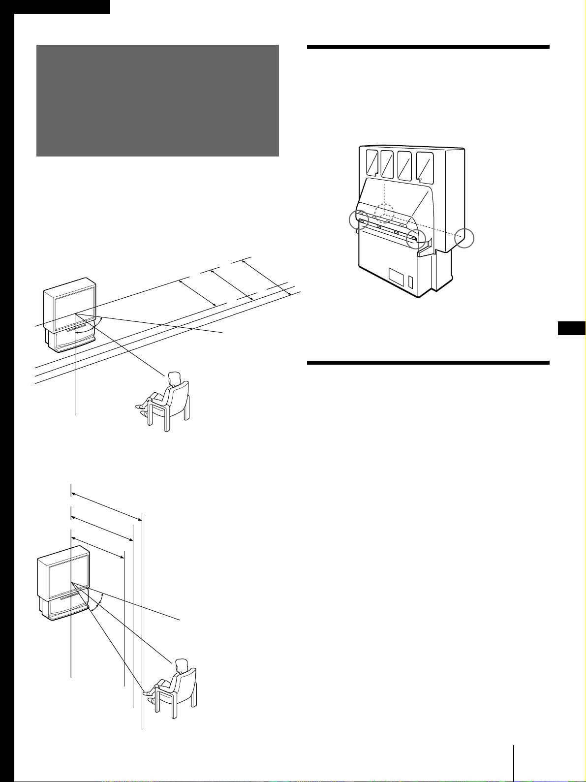
Step 1: Installing
the projection TV
For the best picture quality, install the projection TV
within the areas shown below.
Optimum viewing area (Horizontal)
Optimum viewing area (Vertical)
(Rear of projection TV)
min. 2.1m (approx. 7 ft.)
53"
min. 1.8m (approx. 6 ft.)
48"
min. 2.4m (approx. 8 ft.)
61"
60°
60°
60°
min. 2.1m (approx. 7 ft.)
53"
min. 1.8m (approx. 6 ft.)
48"
min. 2.4m (approx. 8 ft.)
61"
20°
20°
6
-EN
Getting Started
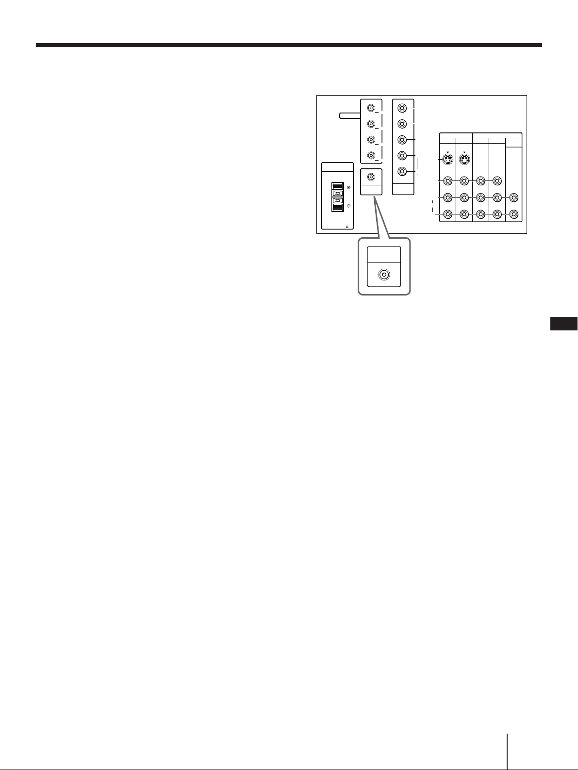
Step 2: Hookup
Connecting an antenna/cable TV
system without a VCR
To cable or antenna
Although you can use either an indoor or outdoor
antenna with your projection TV, we recommend that
you connect an outdoor antenna or a cable TV system
to get better picture quality.
Connecting an antenna
Connect your antenna cable to the VHF/UHF antenna
terminal. If you cannot connect your antenna cable
directly to the terminal, follow one of the instructions
below depending on your cable type.
To cable box and cable
Pay cable TV systems use scrambled or encoded signals
requiring a cable box* in addition to the normal cable
connection.
* The cable box will be supplied by the cable company.
Note
• You cannot watch the signal through an AUX connector as a
window picture.
To cable and antenna
Note
• Do not connect anything to the TO CONVERTER connector in
this case.
A
75-ohm coaxial cable
B
• VHF only
or
• UHF only
or
• VHF/UHF
C
Notes
• Most VHF/UHF combination antennas have a signal splitter.
Remove the splitter before attaching the appropriate connector.
• If you use the U/V mixer, snow and noise may appear in the
picture when viewing cable TV channels over 37.
EAC-66 U/V mixer
(not supplied)
• VHF
and
• UHF
75-ohm coaxial cable
300-ohm twin lead cable
300-ohm twin lead cable
Antenna connector
• VHF only
or
• VHF/UHF
or
• Cable
(Rear of projection TV)
VHF/UHF
(Rear of projection TV)
VHF/UHF
(Rear of projection TV)
VHF/UHF
Cable
To cable box
If your cable company requires you to connect a cable
box, make the connection as follows:
(Rear of projection TV)
VHF/UHF
(Rear of projection TV)
VHF/UHF
Cable
Cable box
IN OUT
CATV cable
75-ohm coaxial
cable (not supplied)
Cable box
TO
CONVERTER
VHF/UHF
(Rear of projection TV)
AUX
CATV cable
Antenna cable
TO
CONVERTER
VHF/UHF
(Rear of projection TV)
AUX
Getting Started
7
-EN
EN
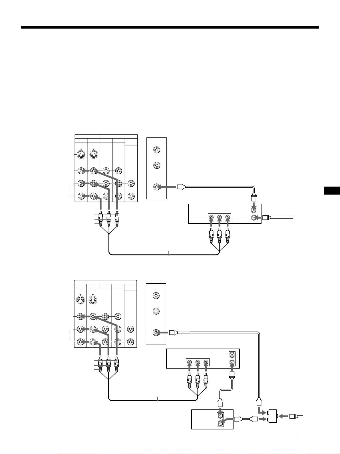
Connecting an antenna/cable TV system with a VCR
After making these connections, you will be able to do
the following:
• View the playback of video tapes
• Record one TV program while viewing another
program
• Watch two TV programs at once using PIP
For details on connection, see your VCR instruction
manual.
Before making the connection, disconnect the AC
power cords of the equipment to be connected.
To a conventional VCR
Note
• To connect a monaural VCR, connect the audio output of the
VCR to AUDIO-L (MONO) of VIDEO 1/3 IN on the projection
TV.
Without a cable box
VIDEO (yellow)
AUDIO-L (white)
AUDIO-R (red)
Splitter (not supplied)
Antenna
cable
VIDEO (yellow)
AUDIO-L (white)
AUDIO-R (red)
VMC-810S/820S
(not supplied)
Antenna cable
VHF/UHF
Antenna cable
Rear of projection TV
VCR
With a cable box
VCR
Antenna cable
Cable box
VMC-810S/820S
(not supplied)
VHF/UHF
Video
and
audio
outputs
VHF/UHF
input
Video and audio
outputs
VHF/UHF
input
VHF/UHF
output
VHF/UHF
output
AUX
TO
CONVERTER
VHF/UHF
AUDIO VIDEO
LINE
OUT
OUT
IN
IN
VIDEO 1 VIDEO 3
S VIDEO
VIDEO
L
R
AUDIO
(
MONO
)
OUT
TV
MONITOR AUDIO
(VAR/FIX)
OUT
IN
OUT
AUDIO VIDEO
LINE
OUT
IN
AUX
TO
CONVERTER
VHF/UHF
IN
VIDEO 1 VIDEO 3
S VIDEO
VIDEO
L
R
AUDIO
(
MONO
)
OUT
TV
MONITOR AUDIO
(VAR/FIX)
Rear of projection TV
8
-EN
Getting Started
Antenna cable
To an S video equipped VCR
If your VCR has an S VIDEO output connector, make
the following connections.
Whenever you connect the cable to the S VIDEO input
connector, the projection TV automatically receives S
video signals.
Without a cable box
With a cable box
S VIDEO
S VIDEO
Rear of projection TV
Note
• Video signals are composed of Y (luminance) and C (chroma)
signals. The S connection sends the two signals separately
preventing degradation, and gives better picture quality
compared to conventional connections.
RK-74A
(not supplied)
YC-15V/30V
(not supplied)
VCR
Antenna cable
Cable box
Splitter
(not supplied)
Antenna
cable
VHF/UHF
Antenna cable
YC-15V/30V
(not supplied)
RK-74A
(not supplied)
VHF/UHF
VCR
Audio
outputs
VHF/UHF
input
VHF/UHF
output
S video output
Audio
outputs
VHF/UHF
input
S video output
AUDIO-L (white)
AUDIO-R (red)
AUDIO-L (white)
AUDIO-R (red)
OUT
IN
AUDIO VIDEO S VIDEO
LINE
OUT
AUX
TO
CONVERTER
VHF/UHF
VIDEO 1 VIDEO 3
S VIDEO
VIDEO
L
R
AUDIO
(
MONO
)
TV
IN
OUT
MONITOR AUDIO
(VAR/FIX)
Rear of projection TV
AUX
TO
CONVERTER
VHF/UHF
AUDIO VIDEO S VIDEO
LINE
OUT
OUT
IN
OUT
IN
VIDEO 1 VIDEO 3
S VIDEO
VIDEO
L
R
AUDIO
(
MONO
)
TV
IN
OUT
MONITOR AUDIO
(VAR/FIX)
Getting Started
9
-EN
EN
Connecting a DBS receiver
For details on connection, see the instruction manual of
the DBS (Digital Broadcasting Satellites) receiver.
To a projection TV
VMC-810S/820S (not supplied)
VIDEO (yellow)
AUDIO-L (white)
AUDIO-R (red)
VHF/UHF
Cable or cable box
Antenna
Note
• You can use the S VIDEO connector or the composite video
connector for the video connection.
To a projection TV and VCR
DBS receiver
Satellite
antenna
input
Cable or cable box
DBS receiver
Antenna
VMC-810S/820S (not supplied)
VIDEO (yellow)
AUDIO-L (white)
AUDIO-R (red)
VCR
Satellite
antenna
input
VHF/
UHF OUT
F-type cable
(not supplied)
VHF/
UHF IN
Audio
outputs
Video
output
Audio
outputs
Video
output
Audio
inputs
Video
input
Audio
outputs
Video
output
AUX
TO
CONVERTER
VHF/UHF
S VIDEOAUDIO VIDEO
VHF/UHF
OUT
IN
LINE IN
LINE OUT
IN
VIDEO 1 VIDEO 3
S VIDEO
VIDEO
L
R
AUDIO
(
MONO
)
OUT
TV
MONITOR AUDIO
(VAR/FIX)
AUX
TO
CONVERTER
VHF/UHF
IN
VIDEO 1 VIDEO 3
S VIDEO
VIDEO
L
R
AUDIO
(
MONO
)
OUT
TV
MONITOR AUDIO
(VAR/FIX)
S VIDEOAUDIO VIDEO
VHF/UHF
OUT
IN
LINE IN
LINE OUT
S VIDEOAUDIO VIDEO
VHF/UHF
OUT
IN
LINE IN
LINE OUT
Rear of projection TV
Rear of projection TV
10
-EN
Getting Started
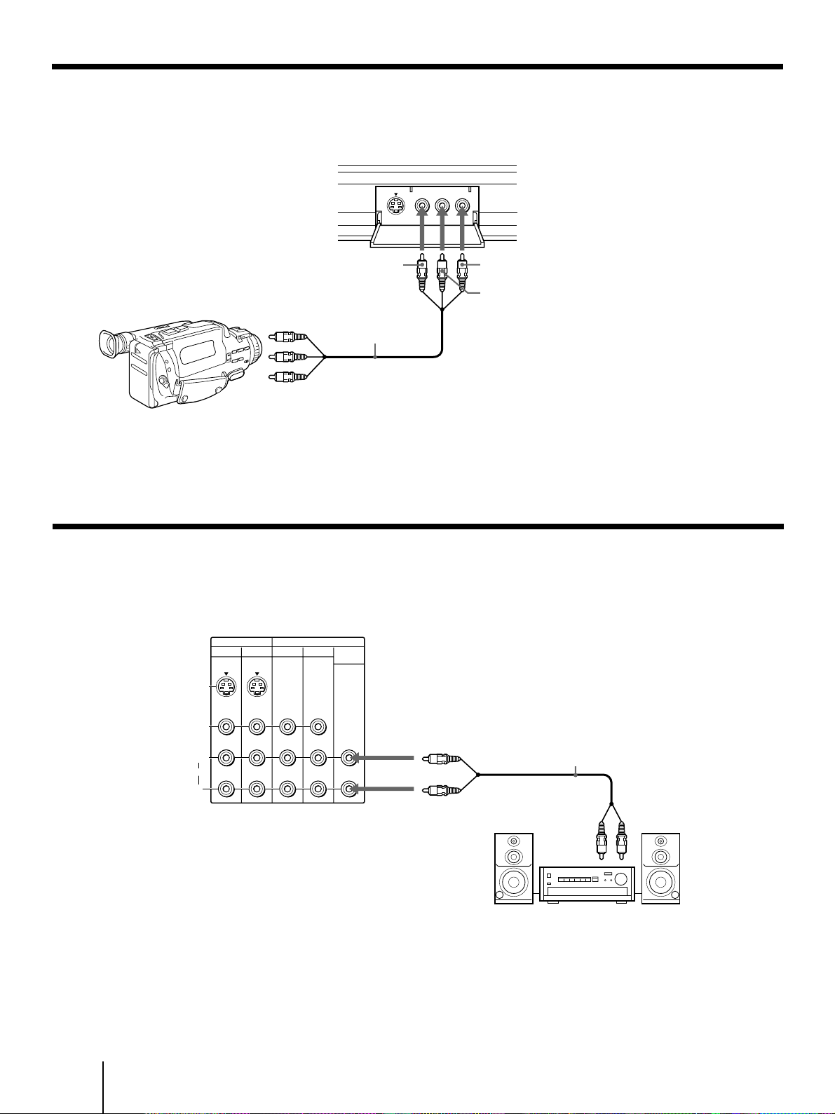
Connecting a camcorder
Use this connection to view a camcorder picture.
AUDIO-L (white)
AUDIO-R (red)
VIDEO
(yellow)
VMC-810S/820S
(not supplied)
Video and
audio outputs
Notes
• To connect a monaural camcorder, connect the audio output of
the camcorder to AUDIO-L (MONO) of VIDEO 2 INPUT on
the projection TV.
Front of projection TV
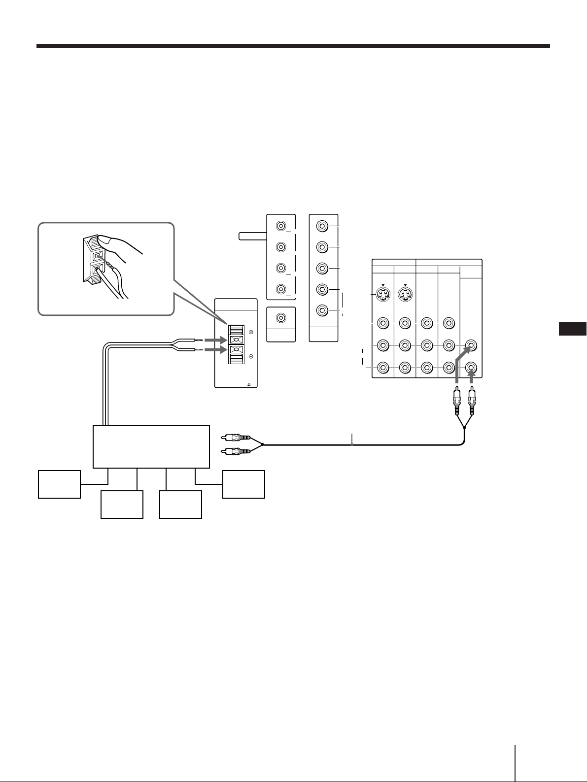
Connecting an audio system
When connecting audio equipment, see page 32 for
more information.
AUDIO OUT-L
(VAR/FIX) (white)
AUDIO OUT-R
(VAR/FIX) (red)
RK-74A (not supplied)
Set the amplifier’s
function to line input.
Line
input
Note
• You can adjust the bass, treble, and balance, or select surround
(page 33) or an MTS (Multichannel TV Sound) mode (page 34)
with the supplied remote control.
• To connect a camcorder equipped with the S video output,
connect the S video output of the camcorder to the S VIDEO
connector of the projection TV.
Stereo amplifier
IN
VIDEO 1 VIDEO 3
S VIDEO
VIDEO
L
R
AUDIO
(
MONO
)
OUT
TV
MONITOR AUDIO
(VAR/FIX)
Rear of projection TV
VIDEO
S VIDEO
VIDEO 2 INPUT
L(MONO)-AUDIO-R
Getting Started
11
-EN
EN
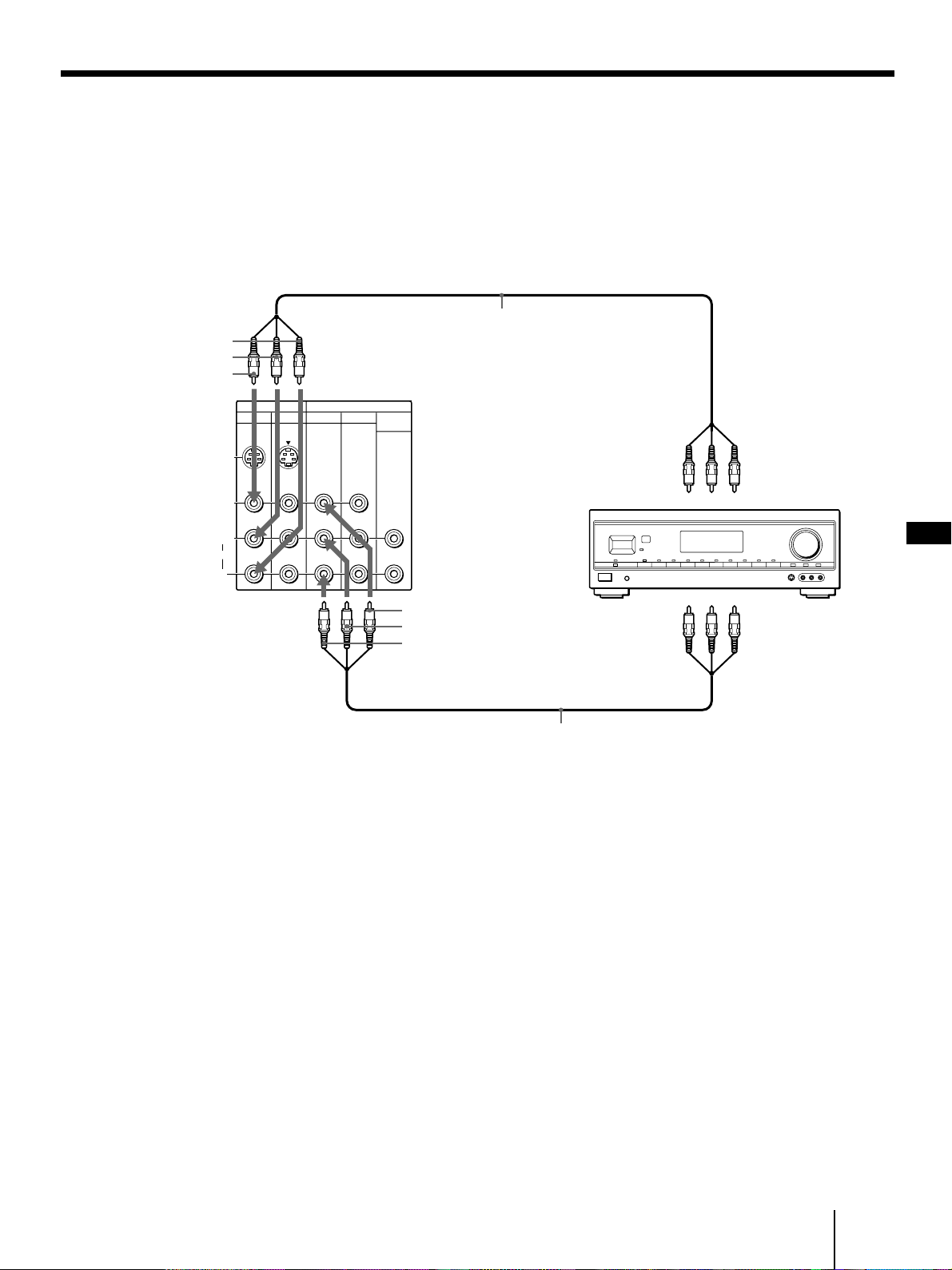
Connecting an AV receiver
Connect an optional AV receiver to the VIDEO 1 IN
jacks at the rear of the projection TV.
If your AV receiver has the TV input jacks, connect
them to the TV OUT jacks at the rear of the projection
TV.
AUDIO-R (red)
AUDIO-L (white)
VIDEO (yellow)
VIDEO (yellow)
AUDIO-L (white)
AUDIO-R (red)
VMC-810S/820S
(not supplied)
VMC-810S/820S
(not supplied)
Monitor video
output
Monitor audio
output
AV receiver
TV audio input
TV video input
IN
VIDEO 1 VIDEO 3
S VIDEO
VIDEO
L
R
AUDIO
(
MONO
)
OUT
TV
MONITOR AUDIO
(VAR/FIX)
Rear of
projection TV
12
-EN
Getting Started
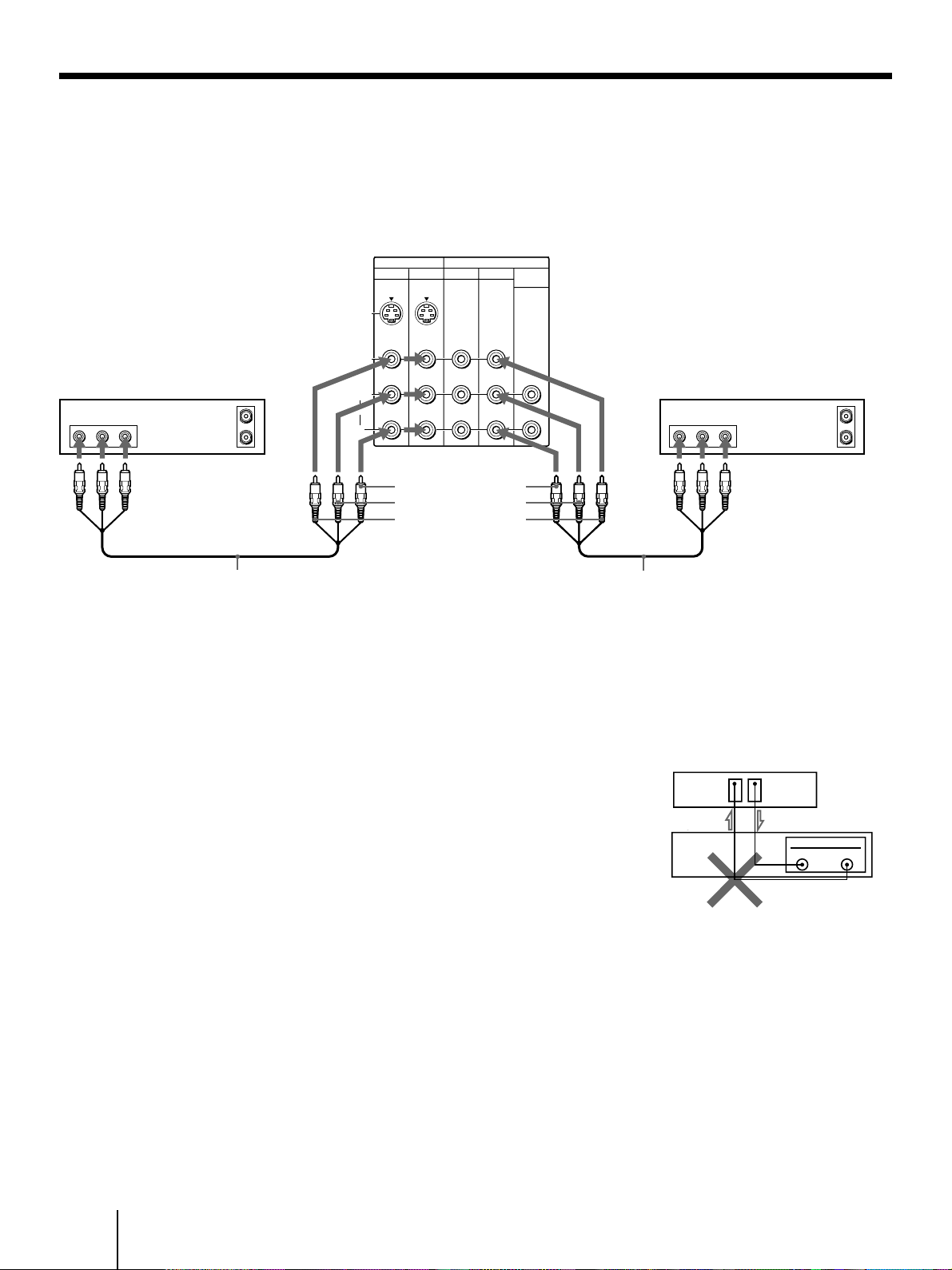
Connecting two VCRs for tape editing using MONITOR OUT
You can record input images displayed on the screen.
This type of connection should be used only when you
connect from the line input of one VCR, and from the
line output of a second VCR.
Notes
• Do not change the input signal while editing through
MONITOR OUT, or the output signal will also change.
• You can use the S video jack to connect a VCR for playback
and the composite video connector to connect a VCR for
recording.
AUDIO-R (red)
AUDIO-L (white)
VIDEO (yellow)
VCR (for playback)
VCR (for recording)
VMC-810S/820S
(not supplied)
VMC-810S/820S
(not supplied)
• When connecting a single VCR to the projection TV, do not
connect the MONITOR OUT to the VCR’s line input, while at
the same time connecting from the projection TV’s VIDEO IN
connectors to the VCR’s line output, as shown below.
DO NOT CONNECT IN THIS WAY.
Video/audio
outputs
Video/audio
inputs
AUDIO VIDEO
LINE
OUT
OUT
IN
AUDIO VIDEO
LINE
IN
OUT
IN
IN
VIDEO 1 VIDEO 3
S VIDEO
VIDEO
L
R
AUDIO
(
MONO
)
OUT
TV
MONITOR AUDIO
(VAR/FIX)
CONTROL S
OUT
Rear of projection TV
LINE
IN OUT
MONITOR
OUT
VIDEO IN
VCR
Rear of projection TV
VCR
Getting Started
13
-EN
EN
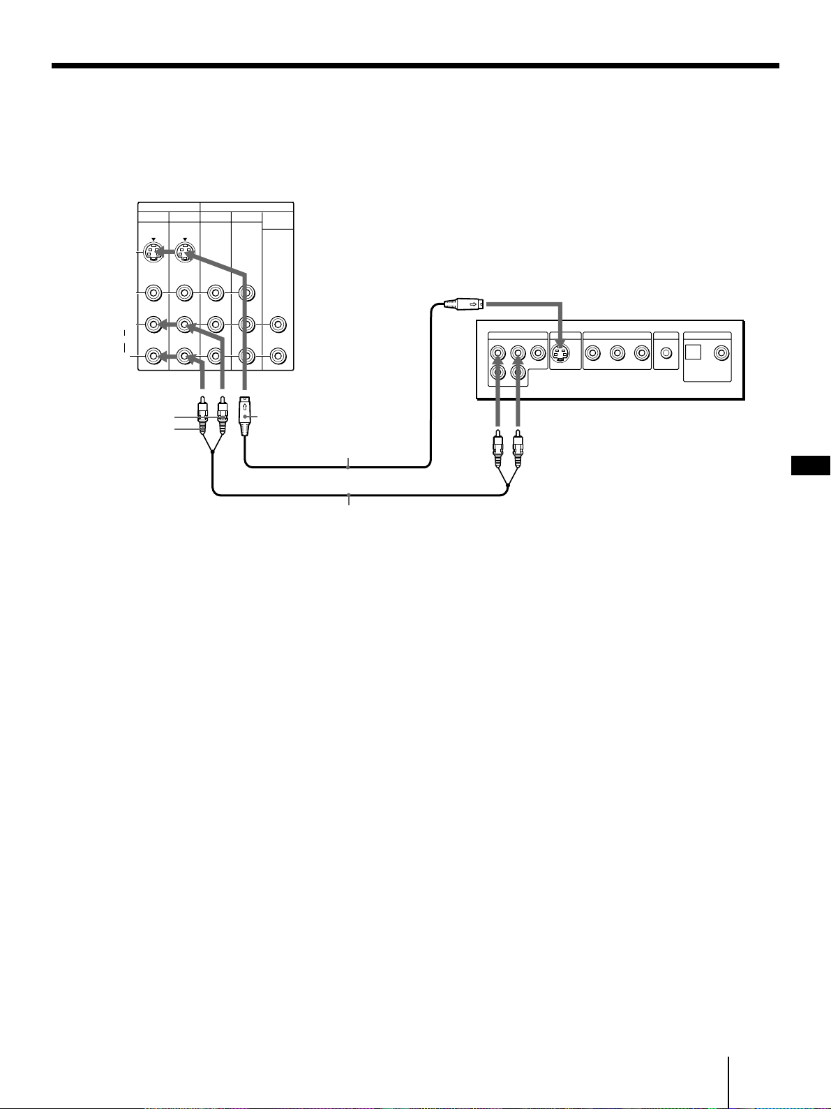
Connecting a DVD player without component video output connectors
Connect VIDEO 1/3 connectors on the projection TV to
line output connectors on the DVD player.
Notes
• Connect your DVD player directly to your TV. Connecting the
DVD player through other video equipment will cause
unwanted picture noise.
• If your DVD player does not have S video output connector,
use composite video connector for the video connection.
• Video signals are composed of Y (luminance) and C (chroma)
signals. The S connection sends the two signals separately
preventing degradation, and gives better picture quality
compared to conventional connections.
• Because the high quality pictures on a DVD disc contain a lot of
information, picture noise may appear. In this case, reduce the
SHARPNESS level in the VIDEO menu (see SHARPNESS on
page 31).
(continued)
S VIDEO
RK-74A
(not supplied)
Audio
outputs
S video
output
AUDIO-L (white)
AUDIO-R (red)
YC-15V/30V
(not supplied)
DVD
VIDEO 1 VIDEO 3
S VIDEO
VIDEO
L
R
AUDIO
(
MONO
)
TV
IN
OUT
MONITOR AUDIO
(VAR/FIX)
LINE OUT
S VIDEO OUT COMPONENT VIDEO OUT
S-LINK
DIGITAL OUT
OPTICAL COAXIALR-AUDIO 1-L VIDEO
YC
B
C
R
TV
Rear of projection TV
14
-EN
Getting Started
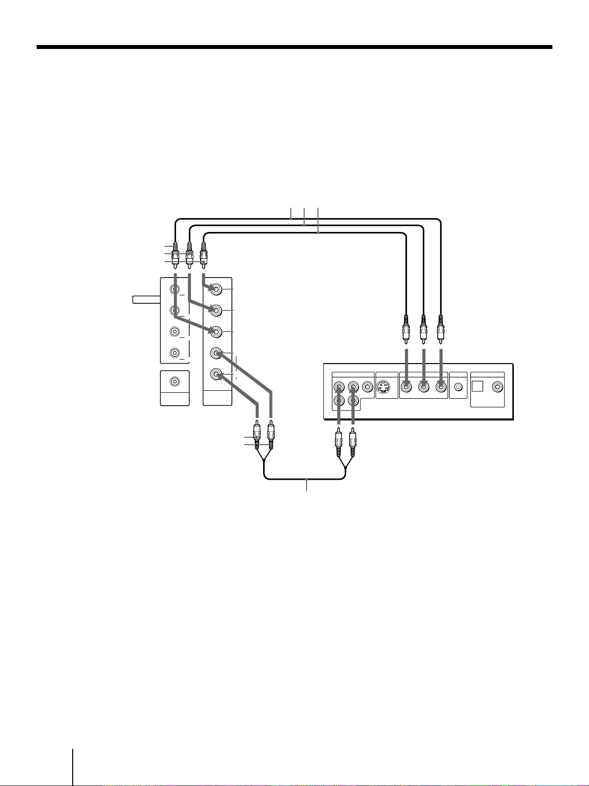
Connecting a DVD player with component video output connectors
Component video terminals Y/CB/CR provide a
sharper, higher resolution picture by reducing the
amount of signal processing thus creating a more
accurate reproduction of the source.
If your DVD player has component video output
connectors, connect them to VIDEO 4 IN on the
projection TV in the following way.
Notes
• Connect your DVD player directly to your TV. Connecting the
DVD player through other video equipment will cause
unwanted picture noise.
• When the DVD player is connected using VIDEO 4 IN, its
MONITOR OUT signals cannot be output.
• Some DVD player connectors may be labeled Y, B-Y, and R-Y.
In this case, connect Y (green) on the projection TV to Y on the
DVD player, C
B (blue) to B-Y, and CR (red) to R-Y.
• The jacks of this projection TV are colored in green (Y), blue
(C
B), and red (CR). If line output connectors of your DVD player
have different colors, make connections according to their
labels.
• Because the high quality pictures on a DVD disc contain a lot of
information, picture noise may appear. In this case, reduce the
SHARPNESS level in the VIDEO menu (see SHARPNESS on
page 31).
• If the incorrect colors appear when using this component video
input, recheck the connections they may be reversed.
Rear of projection TV
DVD
Audio
outputs
Component video
outputs
RK-74A
(not supplied)
VMC-10HG
(not supplied)
CR (red)
CB (blue)
Y (green)
AUDIO-R (red)
AUDIO-L (white)
LINE OUT
S VIDEO OUT COMPONENT VIDEO OUT
S-LINK
DIGITAL OUT
OPTICAL COAXIALR-AUDIO 1-L VIDEO
YC
B
C
R
C
B
C
R
Y
CONTROL S
OUT
L
R
AUDIO
VIDEO 4
IN
VIDEO4
TV OUT
VIDEO1
VIDEO3
S-LINK
15
-EN
Getting Started
EN
VIDEO 1 VIDEO 3
S VIDEO
C
B
C
R
Y
VIDEO
AUDIO
(
MONO
)
TV
IN
OUT
MONITOR AUDIO
(VAR/FIX)
CONTROL S
OUT
L
R
AUDIO
VIDEO 4
IN
VIDEO4
VIDEO1
VIDEO3
IN
CENTER SPEKER
30W(NOM)
60W(MAX)16
S-LINK
TV OUT
L
R
Connecting an amplifier with Dolby Pro Logic decoder
If you use an amplifier with Dolby Pro Logic decoder
instead of the projection TV’audio system, you can still
use the projection TV’s center speaker. See “Setting the
speaker switch (SPEAKER)” on page 35.
* Manufactured under license from Dolby Laboratories
Licensing Corporation. Additionally licensed under Canadian
patent number 1,037,877. “Dolby”, the double-D symbol a
and “Pro Logic” are trademarks of Dolby Laboratories
Licensing Corporation.
Rear of projection TV
AUDIO OUT-L
(VAR/FIX) (white)
AUDIO OUT-R
(VAR/FIX) (red)
RK-74A (not supplied)
CENTER SPEAKER IN ‘
CENTER SPEAKER IN ’
Amplifier with Dolby*
Pro Logic decoder
Rear
speaker
(L)
Front
speaker
(L)
Front
speaker
(R)
Rear
speaker
(R)
16
-EN
Getting Started
Rear of projection TV
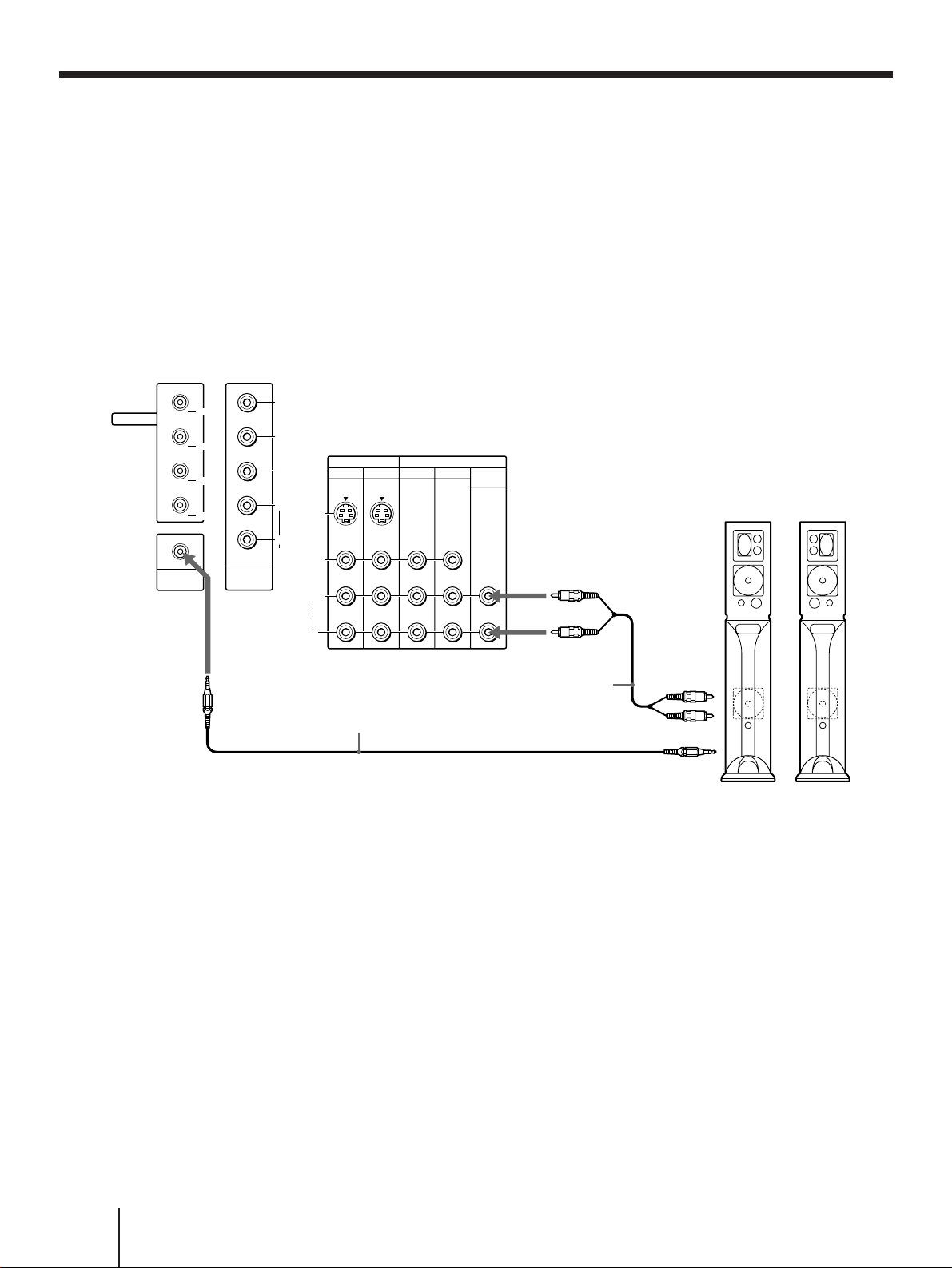
Connecting a Sony SAVA series speaker system
If you have a Sony SAVA series speaker system,
connect your speakers to the AUDIO (VAR/FIX) OUT
jacks on the rear of the projection TV with the audio
cable supplied with the speakers. You can take
advantage of the speakers’ Dolby Pro Logic surround
system and super woofer mode, and control them with
the supplied remote control. When connecting a Sony
SAVA series speaker system, see page 35 for more
information.
RK-G34, etc. (not supplied)
1 IN L
1 IN R
SAVA series speaker system
Front left
Audio cord supplied
with the speakers
CONTROL S OUT
AUDIO OUT-R
(VAR/FIX) (red)
AUDIO OUT-L
(VAR/FIX) (white)
CONTROL S IN
VIDEO 1 VIDEO 3
S VIDEO
C
B
C
R
Y
VIDEO
L
R
AUDIO
(
MONO
)
TV
IN
OUT
MONITOR AUDIO
(VAR/FIX)
CONTROL S
OUT
L
R
AUDIO
VIDEO 4
IN
VIDEO4
TV OUT
VIDEO1
VIDEO3
S-LINK
17
-EN
Getting Started
EN
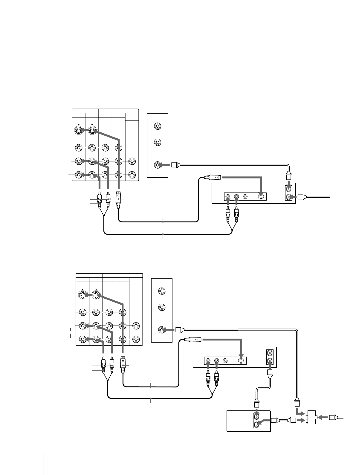
Using the S-Link function
S-Link function is a Sony innovation designed to make
your Sony components work together. It allows you to
switch automatically the TV’s input mode to video
when you press the play button on your Sony S-Link
VCR. It also allows you to turn the VCR and TV off at
the same time with the SYSTEM OFF button on the
remote control (see page 44 for details).
Using the S-Link function without a
Sony AV receiver
To make use of this function, be sure to connect the
video equipment to the VIDEO IN and S-LINK
connectors with the same label, that is, to VIDEO 1 IN
and S-LINK VIDEO 1, to VIDEO 3 IN and S-LINK
VIDEO 3, and to VIDEO 4 IN and S-LINK VIDEO 4.
Rear of projection TV
AUDIO-R (red)
AUDIO-L (white)
VIDEO (yellow)
Audio/video cable
(not supplied)
S-LINK VIDEO 1/3
Sony VCR
Audio/video
outputs
S-LINK
AUDIO-R (red)
AUDIO-L (white)
Y (green)
CB (blue)
CR (red)
S-LINK VIDEO 4
S-LINK
Component
video outputs
Audio
outputs
VMC-10HG
(not supplied)
RK-74A (not supplied)
Sony DVD
Refer also to the Operating Instructions supplied with
your VCR, DBS tuner, LD player, and other Sony video
equipment for details.
Notes
• The projection TV may malfunction if you connect the S-Link
cable to the projection TV without connecting the other end of
the cable to the VCR.
• When making the S-Link connection, be sure to insert all the
connectors firmly.
(continued)
LINE OUT
S VIDEO OUT COMPONENT VIDEO OUT
S-LINK
DIGITAL OUT
OPTICAL COAXIALR-AUDIO 1-L VIDEO
YC
B CR
LINE OUT
S-LINK
AUDIO VIDEO
LINE IN
VIDEO 1 VIDEO 3
S VIDEO
C
B
CR
Y
VIDEO
L
R
AUDIO
(
MONO
)
TV
IN
OUT
MONITOR AUDIO
(VAR/FIX)
CONTROL S
OUT
L
R
AUDIO
VIDEO 4
IN
VIDEO4
TV OUT
VIDEO1
VIDEO3
S-LINK
RK-G34, etc.
(not supplied)
18
-EN
Getting Started
LINE OUT
S-LINK
AUDIO VIDEO
LINE IN
LINE OUT
S-LINK
AUDIO VIDEO
LINE IN
VIDEO 1 VIDEO 3
S VIDEO
C
B
C
R
Y
VIDEO
L
R
AUDIO
(
MONO
)
TV
IN
OUT
MONITOR AUDIO
(VAR/FIX)
CONTROL S
OUT
L
R
AUDIO
VIDEO 4
IN
VIDEO4
TV OUT
VIDEO1
VIDEO3
S-LINK
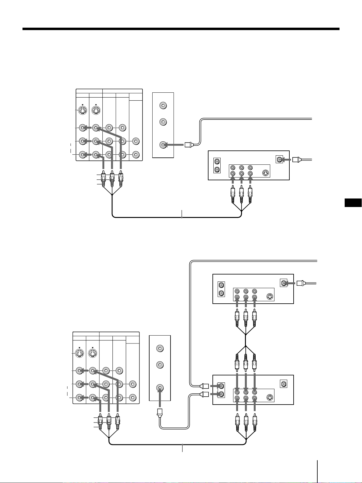
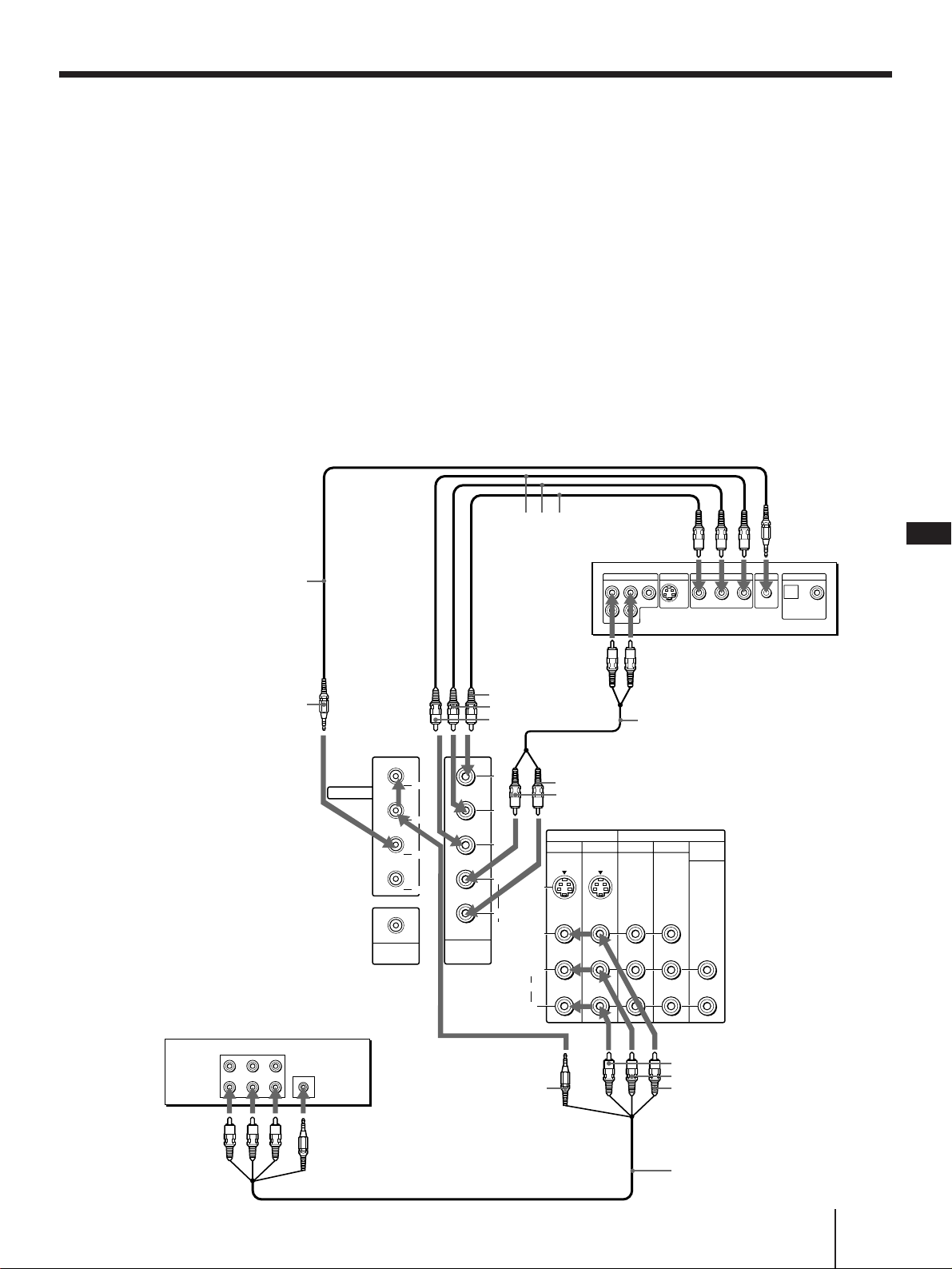
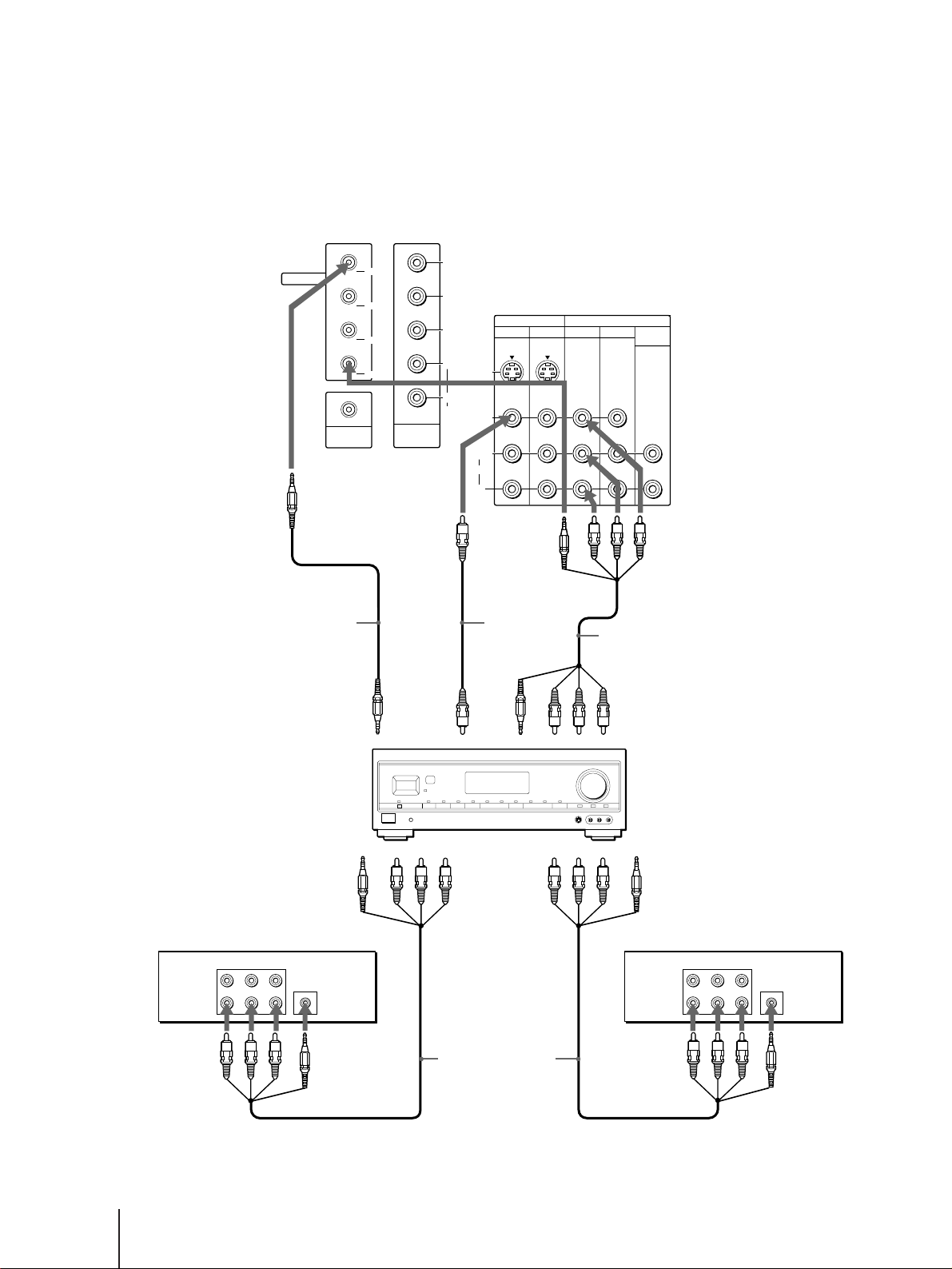
Using the S-Link function with a Sony
AV receiver
When making S-Link connections through a Sony AV
receiver, set the TV speaker switch to OFF, CENTER or
SAVA SP, but never to ON (see page 35).
Sony VCR
S-LINK
TV OUT
Sony VCR
TV OUT
VIDEO 1 IN
VIDEO
S-LINK
VIDEO 1
MONITOR OUT
(S-LINK)
MONITOR
OUT
(Video
output)
RK-G34, etc.
(not supplied)
Video cable
(not supplied)
Audio/video cable
(not supplied)
TV IN (S-LINK and
video/audio inputs)
Sony
AV receiver
VIDEO 1 IN
(S-LINK and
video/audio inputs)
VIDEO 2 IN
(S-LINK and
video/audio inputs)
Audio/video cable
(not supplied)
Refer also to the Operating Instructions supplied with
your VCR, DBS tuner, LD player, AV receiver, and
other Sony video equipment for details.
Rear of projection TV
Audio/video
outputs
S-LINK
Audio/video
outputs
S-LINK
19
-EN
Getting Started
EN
Connecting other Sony equipment with CONTROL S jack
This feature allows you to control your projection TV
and other Sony equipment with one remote control.
To control other Sony equipment with the projection
TV’s remote control, connect the input of the
equipment to CONTROL S OUT jack on the projection
TV.
Rear of projection TV
VIDEO 1 VIDEO 3
S VIDEO
C
B
C
R
Y
VIDEO
L
R
AUDIO
(
MONO
)
TV
IN
OUT
MONITOR AUDIO
(VAR/FIX)
CONTROL S
OUT
L
R
AUDIO
VIDEO 4
IN
VIDEO4
TV OUT
VIDEO1
VIDEO3
IN
CENTER SPEKER
30W(NOM)
60W(MAX)16
S-LINK
CONTROL S
OUT
20
-EN
Getting Started
1 2 3
4 5 6
7 8
0
9
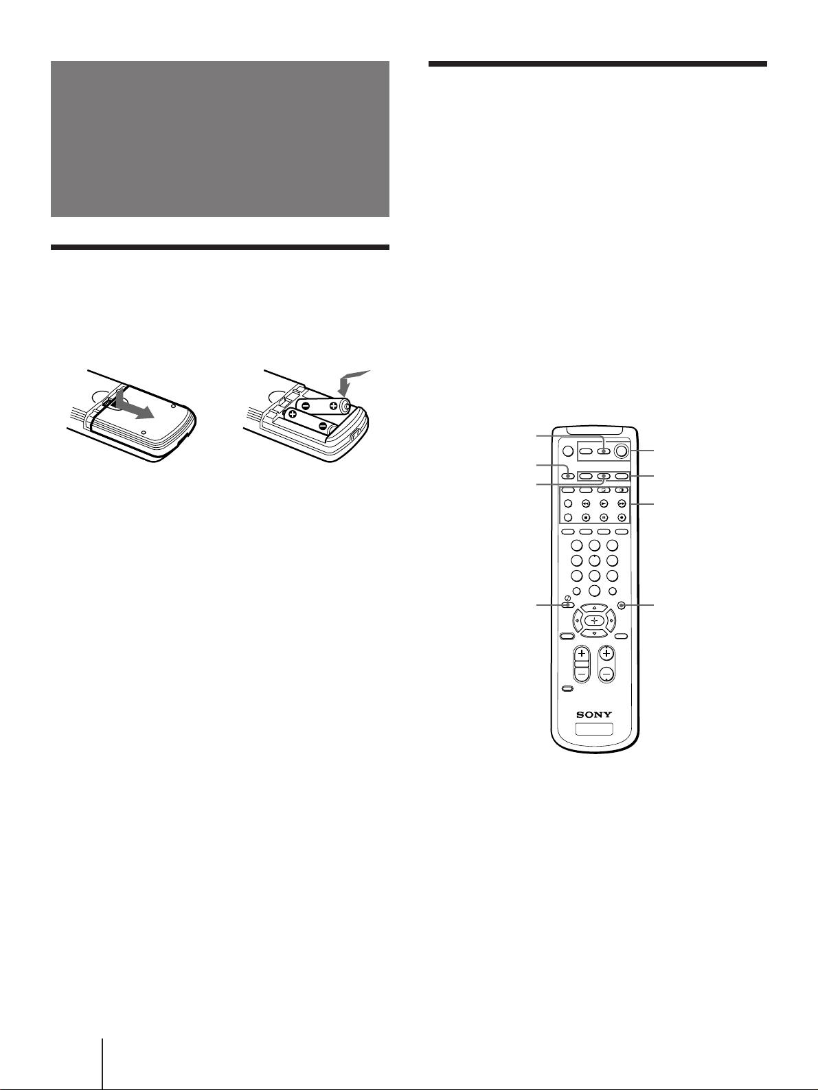
Getting to know buttons on the
remote control
Names of buttons on the remote control are indicated
in different colors to represent the available functions.
Button color
Transparent ....... TV/VCR/DBS/Cable box function
(light up)
buttons. Press the appropriate
function button first to change the
remote control’s function.
Green .................. Buttons relevant to power operations.
Label color
White .................. TV/VCR/DBS/Cable box operation
buttons.
Yellow................. PIP operation buttons.
Blue ..................... DBS operation buttons.
Step 3: Setting up
the remote
control
Inserting batteries
Insert two size AA (R6) batteries (supplied) by
matching the + and – on the battery to the diagram
inside the battery compartment.
Notes
• Under normal conditions, batteries will last up to six months.
If the remote control does not operate properly or the
indicators of the buttons on the remote control do not light up,
the batteries may be worn out. When replacing batteries,
replace both of them with new ones.
• Do not mix old batteries with new ones or mix different types
of batteries together.
• If the electrolyte inside the battery should leak, wipe the
contaminated area of the battery compartment with a cloth and
replace the old batteries with new ones. To prevent the
electrolyte from leaking, remove the batteries when you don’t
plan to use the remote control for a long period of time.
• Do not handle the remote control roughly. Do not drop it, step
on it, or let it get wet.
• Do not place the remote control in direct sunlight, near a
heater, or where the humidity is high.
Green
Transparent
Yellow
Blue
Blue
Blue
Green
Blue
21
-EN
Getting Started
EN
3 Press CHANNEL +/– or VOLUME + to select
the on-screen menu language.
If you prefer Spanish or French to English, you can
change the on-screen menu language.
All of the menus will be set to the factory preset
condition in the selected language.
4 Press VOLUME – to start AUTO SET UP.
5 Press CHANNEL + to preset channels.
“AUTO PROGRAM” appears on the screen and the
TV starts scanning and presetting channels
automatically. When all the receivable channels are
stored, “AUTO PROGRAM” disappears and the
following menu appears. If the projection TV
receives cable TV channels, CABLE is set to ON
automatically.
To exit AUTO PROGRAM
Press any button.
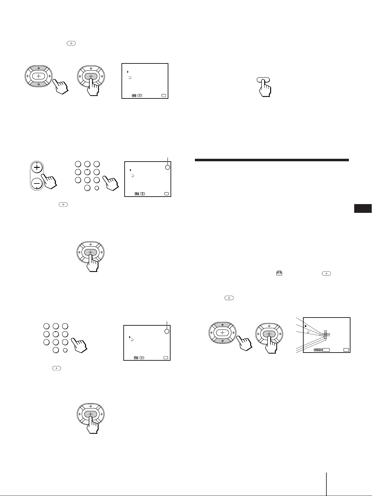
6 Adjust convergence.
(1) Press CHANNEL +.
The CONVERGENCE adjustment screen
appears.
RED
[]
:
TV/VIDEO
E
[]
:
SET UP
CONVERGENCE
:
RED
[]
CH
+
[]
CH
–
[]
VOL
+[]
VOL
–
/ BLUE
xit
YES
[]
:
CH
+
NO
[]
:
CH
–
CONTINUE TO
CONVERGENCE?
AUTO PROGRAM
YES
[]
:
CH
+
NO
[]
:
CH
–
CONTINUE TO
AUTO PROGRAM?
[
CH
]
+
[
CH
]
–
ENGLISH :
ESPAÑOL :
AUTO SET UP :
DEMO :
[
TV/VIDEO
]
[
VOL
]
–
Press
[
SET UP
]
to exit.
FRANÇAIS :
[
VOL
]
+
SETUP
TV/VIDEO – VOLUME + – CHANNEL + POWER
STEREO STAND BY
TIMER/
– CHANNEL +
– CHANNEL +
– VOLUME +
– VOLUME +
– CHANNEL +
SETUP
Before you start using AUTO SET UP, be sure to
connect the antenna or cable to the projection
TV (see page 6).
1 Press POWER to turn the projection TV on.
2 Press SETUP on the front of the projection
TV.
AUTO SET UP screen appears.
POWER
Step 4: Setting up
the projection TV
automatically
(AUTO SET UP)
You can set up your projection TV easily by using the
AUTO SET UP feature. It presets all the receivable
channels, adjusts the convergence and changes the on-
screen menu language. To set up the projection TV
manually, see “Adjusting convergence” (page 23),
“Setting cable TV on or off” (page 24), “Presetting
channels” (page 25) and “Changing the menu
language” (page 25).
If the projection TV is set to a video input, you cannot
perform AUTO SET UP. Press TV/VIDEO so that a
channel number appears.
(Front of projection TV)
or
R
G
B
B
G
R
R=Red
G=Green
B=Blue
22
-EN
Getting Started
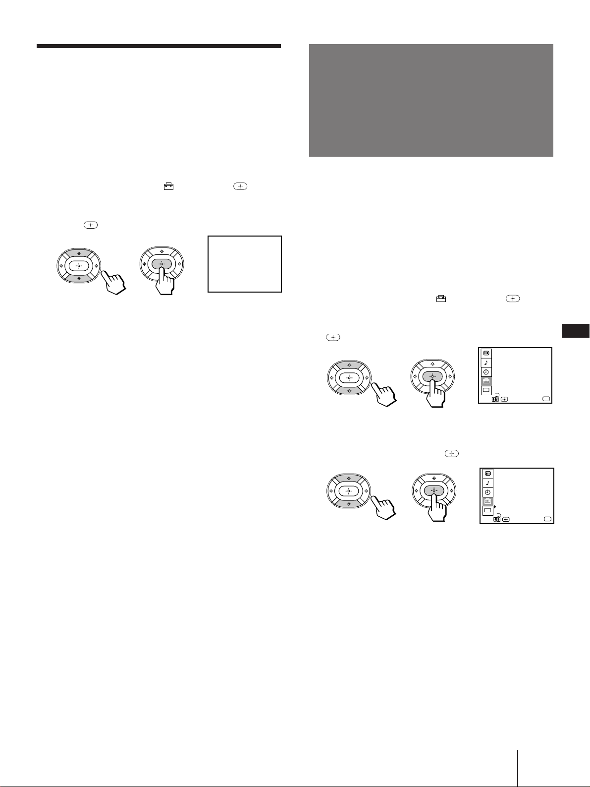
1 Press TV (FUNCTION).
2 Press MENU.
The main menu appears.
3 Press V or v to select , and press .
The SET UP menu appears.
SET UP
CHANNEL ERASE/ADD
CHANNEL CAPTION
CHANNEL BLOCK
FAVORITE CHANNEL
CABLE : ON
AUTO PROGRAM
CONVERGENCE
MENU
VIDEO LABEL
LANGUAGE : ENGLISH
CC
Use
Exit
MENU
VIDEO
PICTURE
HUE
COLOR
BRIGHTNESS
SHARPNESS
Use
Exit
MENU
TRINITONE : HIGH
MENU
MODE : STANDARD
CC
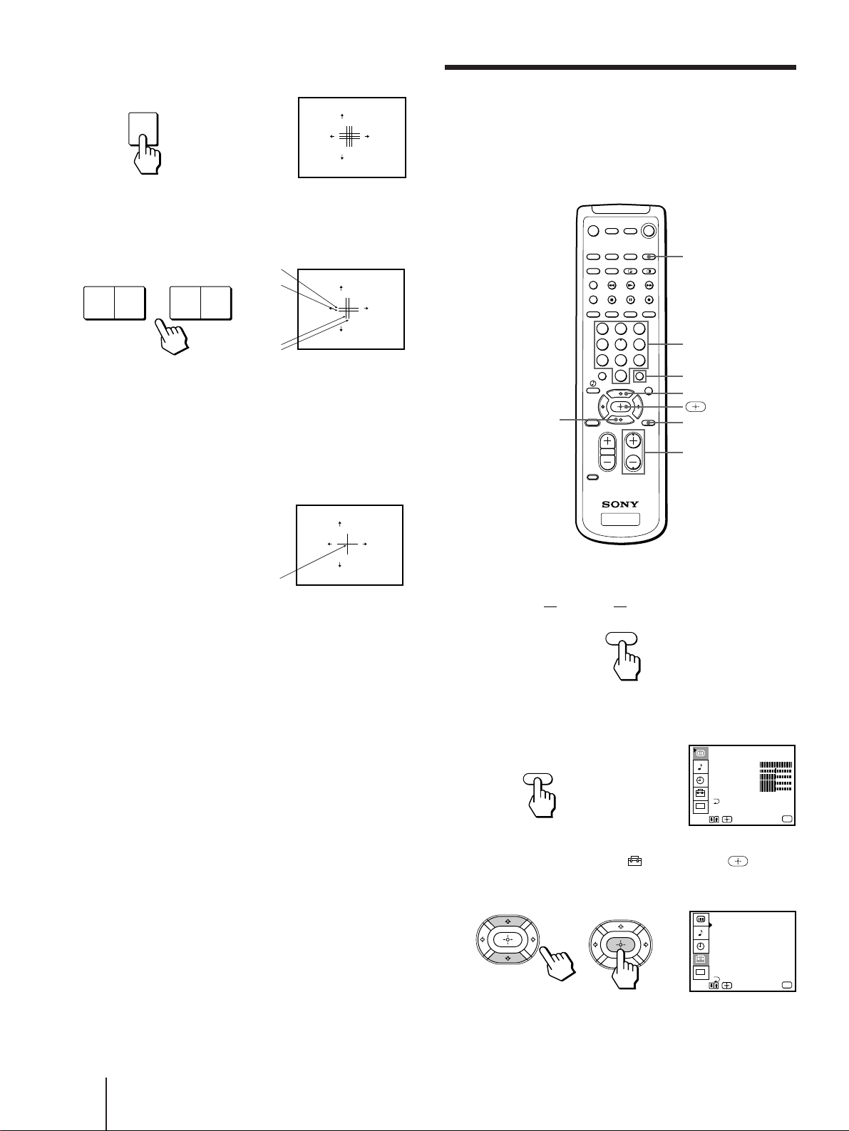
(2) Press TV/VIDEO to select RED or BLUE.
(3) Using CHANNEL +/– or VOLUME +/–, move
the line until it converges with the center green
line.
To move horizontal line up/down, press CHANNEL
+/–.
To move vertical line right/left, press VOLUME +/–.
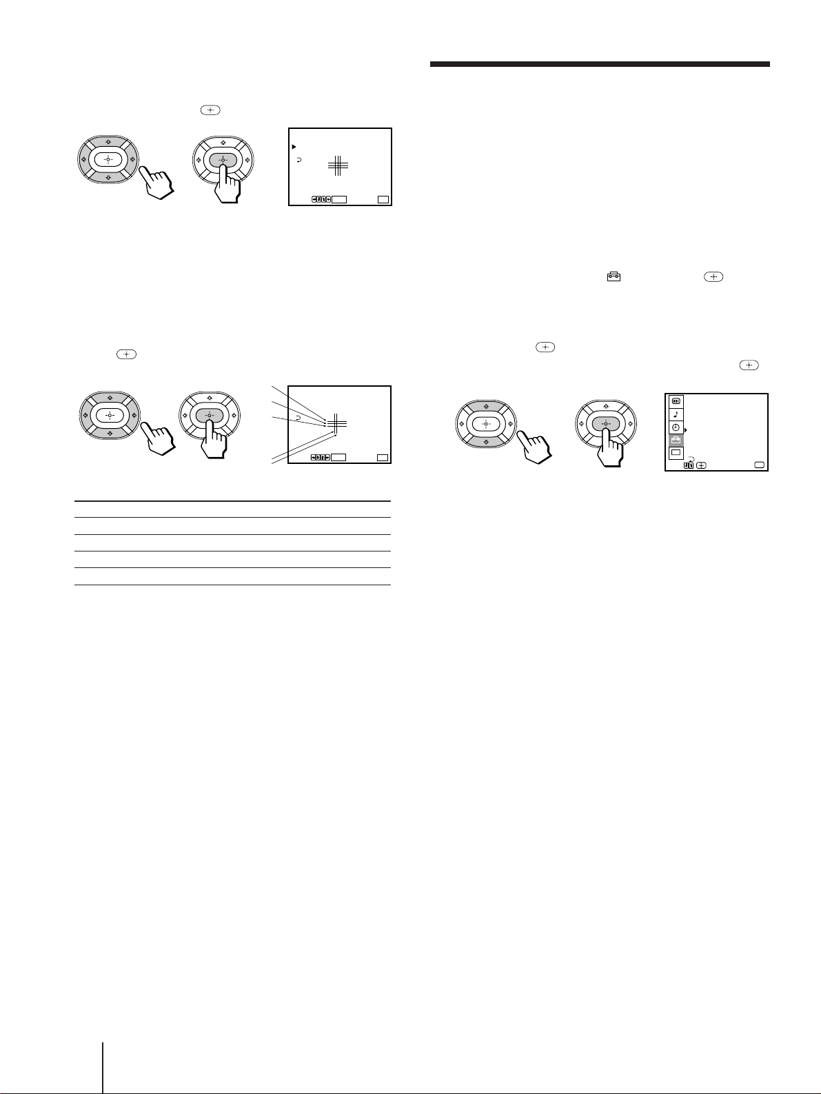
(4) Repeat steps (2) and (3) to adjust the other lines
until all three lines converge and are seen as a
white cross.
Note
• Using the AUX connector, press ANT first and make sure that
“AUX” is displayed beside the channel number on the screen.
Then follow the steps 2 to 6 above to perform AUTO SET UP.
To preview the main functions (DEMO)
Press TV/VIDEO on the projection TV in step 4. The
functions and menus are displayed one by one.
To exit DEMO
Press any button.
RED
[]
:
TV/VIDEO
E
[]
:
SET UP
CONVERGENCE
:
BLUE
[]
CH
+
[]
CH
–
[]
VOL
+[]
VOL
–
/ BLUE
xit
RED
[]
:
TV/VIDEO
E
[]
:
SET UP
CONVERGENCE
:
RED
[]
CH
+
[]
CH
–
[]
VOL
+[]
VOL
–
/ BLUE
xit
RED
[]
:
TV/VIDEO
E
[]
:
SET UP
CONVERGENCE
:
RED
[]
CH
+
[]
CH
–
[]
VOL
+[]
VOL
–
/ BLUE
xit
MENU
– VOLUME + – CHANNEL +
TV/VIDEO
1 2 3
4 5 6
7 8
0
9
B
G+R
B
G+R
White cross
Erasing or adding channels
After AUTO SET UP, you can erase unnecessary
channels or add the channels you want. Preset channels
during the day rather than late at night, when some
channels may not be broadcasting.
TV (FUNCTION)
0 – 9 buttons
>
ENTER
CH +/–
MENU
.
FUNCTION
TV
23
-EN
Getting Started
EN
6 To erase and/or add other channels, repeat
step 5.
7 Press MENU to return to the original screen.
Notes
• If you erase or add a VHF or UHF channel, the cable TV
channel with the same number is also erased or added, and
vice versa.
• Erasing and adding channels is also available for the AUX
input.
Adjusting convergence
(CONVERGENCE)
The projection tube image appears on the screen in
three layers (red, green and blue). If they do not
converge, the color is poor and the picture blurs. To
correct this, adjust convergence.
You do not have to do this procedure if you perform
AUTO SET UP (page 21). Do this procedure only
when you want to adjust it manually.
1 Press MENU.
2 Press V or v to select , and press .
3 Press V or v to select CONVERGENCE, and
press .
The CONVERGENCE adjustment screen appears.
Use
RETURN
Ex
MENU
it
RED
BLUE
MENU
CONVERGENCE
+
+
R
G
B
B
G
R
R=Red
G=Green
B=Blue
MENU
4 Press V or v to select CHANNEL ERASE/ADD,
and press .
The CHANNEL ERASE/ADD menu appears.
5 Erase and/or add channels:
To erase an unwanted channel
(1) Make sure the cursor (z) is beside ERASE.
(2) Press CH +/– or the 0 – 9 buttons to select the
channel you want to erase, and press ENTER.
(3) Press .
The “–” indication appears beside the channel
number, showing that the channel is erased
from the preset memory.
CHANNEL ERASE/ADD
ERASE
ADD
33
Use
[
0 – 9
]or [
CH
+/–]
to select the channel.
Use Exit
MENU
MENU
CHANNEL ERASE/ADD
ERASE
ADD
33
Use
[
0 – 9
]or [
CH
+/–]
to select the channel.
Use Exit
MENU
MENU
ENTER
1 2 3
4 5 6
7 8
0
9
CH
Selected channel number
or
To add a channel that you want
(1) Press V or v to move the cursor (z) to ADD.
(2) Press the 0 – 9 buttons to select the channel you
want to add, and press ENTER.
(3) Press .
The “+” indication appears beside the channel
number, showing that the channel is added to
the preset memory.
CHANNEL ERASE/ADD
ERASE
ADD
33
Use Exit
MENU
MENU
ENTER
1 2 3
4 5 6
7 8
0
9
Selected channel number
24
-EN
Getting Started
Setting cable TV on or off
If you have connected the projection TV to a cable TV
system, set CABLE to ON (the factory setting). If not,
set CABLE to OFF.
You do not have to do this procedure if you perform
AUTO SET UP (page 21). Do this procedure only when
you want to set it manually.
1 Press MENU.
2 Press V or v to select , and press .
3 Set CABLE to ON or OFF:
(1) Press V or v to move the cursor (z) to CABLE,
and press .
(2) Press V or v to select ON or OFF, and press .
4 Press MENU to return to the original screen.
Note
• If CABLE appears in gray, the projection TV is set to a video
input and you cannot select CABLE. Press ANT so that a
channel number appears.
4 Press V or v to move the cursor (z) to the
symbol showing the line you want to
adjust, and press .
+RED : Red vertical and horizontal line (left/right/up/
down adjustment)
+BLUE :Blue vertical and horizontal line (left/right/up/
down adjustment)
5 Press V, B, v, or b to move the line until it
converges with the center green line, and
press .
6 Repeat steps 4 and 5 to adjust the other
lines until all three lines converge and are
seen as a white cross.
7 Press MENU to return to the original screen.
SET UP
CHANNEL ERASE/ADD
CHANNEL CAPTION
CHANNEL BLOCK
FAVORITE CHANNEL
CABLE : OFF
AUTO PROGRAM
CC
CONVERGENCE
MENU
VIDEO LABEL
LANGUAGE : ENGLISH
Use
Exit
MENU
RED
BLUE
MENU
CONVERGENCE
+
+
Use
Ex
MENU
it
RETURN
Use
Ex
MENU
it
RED
BLUE
MENU
CONVERGENCE
+
+
RETURN
R
G
B
B
G+R
To move Press
Up V
Down v
Right b
Left B
25
-EN
Getting Started
EN
Presetting channels
You can preset TV channels easily by using the AUTO
PROGRAM feature.
You do not have to do this procedure if you perform
AUTO SET UP (page 21). Do this procedure only when
you want to set it manually.
1 Press MENU.
2 Press V or v to select , and press .
3 Press V or v to select AUTO PROGRAM, and
press .
“AUTO PROGRAM” appears on the screen and the
projection TV starts scanning and presetting
channels automatically. When all the receivable
channels are stored, “AUTO PROGRAM”
disappears and the lowest numbered channel is
displayed.
4 Press MENU to return to the original screen.
To exit AUTO PROGRAM
Press any button.
Notes
• If the AUTO PROGRAM menu appears in gray, the projection
TV is set to a video input and you cannot select AUTO
PROGRAM. Press ANT so that a channel number appears.
• Presetting channels is also available for the AUX input.
If you prefer Spanish or French to English, you can
change the menu language.
You do not have to do this procedure if you select the
language during AUTO SET UP (page 21).
Do this procedure only when you want to set it
manually.
1 Press MENU.
2 Press V or v to select , and press .
3 Press V or v to select LANGUAGE, and press
.
4 Press V or v to select your favorite
language, “ENGLISH”, “ESPAÑOL”, or
“FRANÇAIS” and press .
5 Press MENU to return to the original screen.
Note
• Certain parts of the Spanish or French menus remain in
English.
CC
PREFERENCIAS
BORRAR/AÑADIR CANAL
NOMBRE DEL CANAL
BLOQUEAR CANAL
CANAL FAVORITO
CABLE : SI
AUTO PROGRAMACION
LENGUAJE : ESPA
Ñ
OL
MENU
ETIQUETA DE VIDEO
CONVERGENCIA
Use
Exit
MENU
CC
SET UP
CHANNEL ERASE/ADD
CHANNEL CAPTION
CHANNEL BLOCK
FAVORITE CHANNEL
CABLE : ON
AUTO PROGRAM
LANGUAGE : ENGLISH
MENU
VIDEO LABEL
CONVERGENCE
Use
Exit
MENU
AUTO PROGRAM
Changing the
menu language
26
-EN
Operations
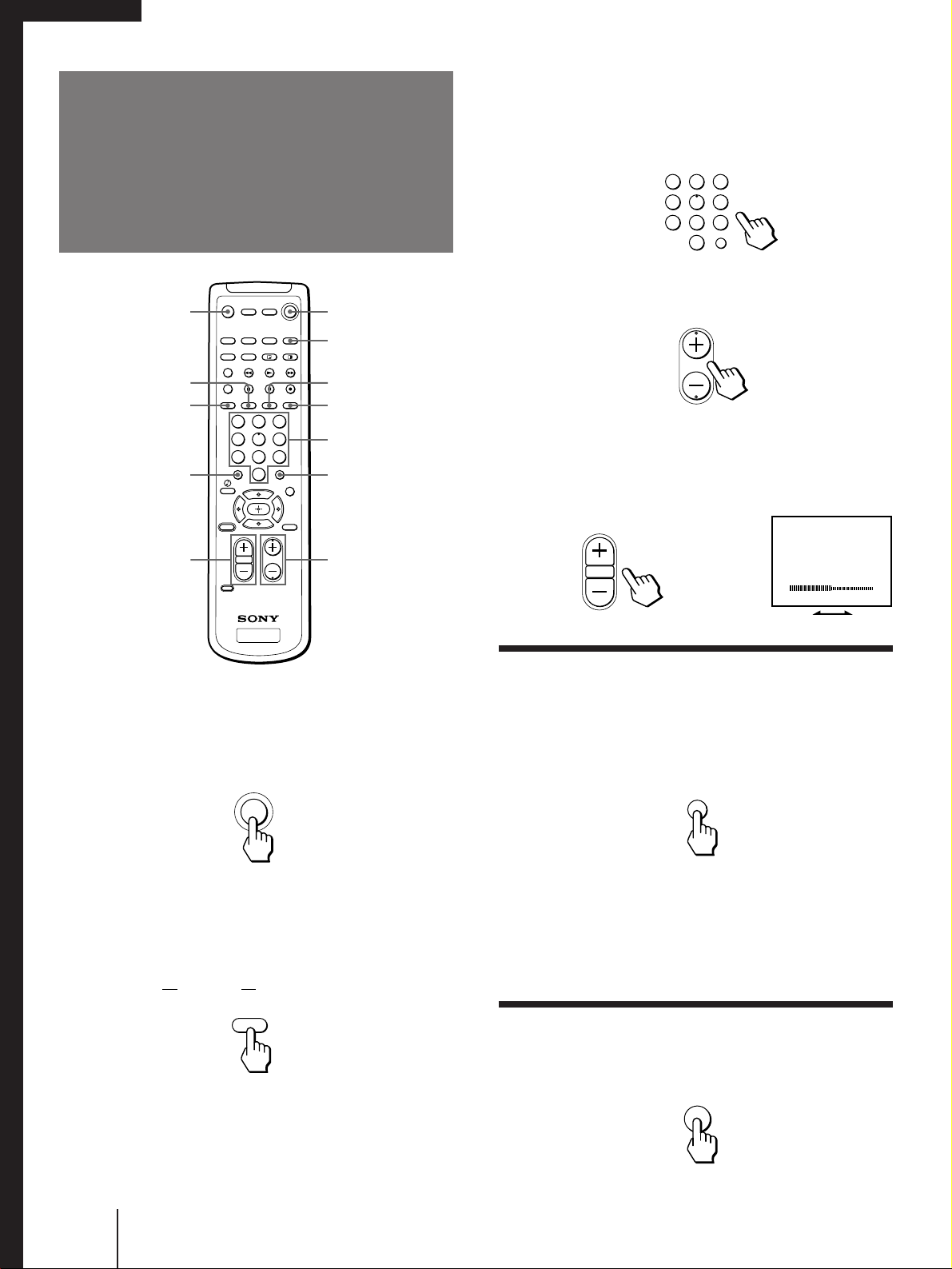
1 Press TV (POWER) to turn on the projection
TV.
The TIMER/STANDBY indicator flashes until the
picture appears.
If “VIDEO” appears on the screen, press ANT so
that a channel number appears.
2 Press TV (FUNCTION).
Once you press TV (FUNCTION), the projection TV
function is set unless another function button is
pressed.
3 Select the channel you want:
To select a channel directly
Press the 0 – 9 buttons, and press ENTER.
For example, to select channel 10, press 1, 0 and
ENTER.
To scan through channels
Press CH +/– until the channel you want appears.
The channel can also be selected without pressing
ENTER.
4 Press VOL +/– to adjust the volume.
Switching quickly between two
channels
You can use the JUMP button to switch or “jump” back
and forth between two channels.
Press JUMP.
Pressing JUMP again switches the channel back to the
one you selected last.
Note
• You cannot jump to channels you scanned through using the
CH +/– buttons.
Muting the sound
Press MUTING.
“MUTING” appears on the screen.
To restore the sound, press MUTING again, or press
VOL +.
VOLUME
MUTING
JUMP
VOL
CH
ENTER
1 2 3
4 5 6
7 8
0
9
FUNCTION
TV
POWER
TV
1 2 3
4 5 6
7 8
0
9
Watching the TV
Operations
TV (POWER)
MUTING
SLEEP
DISPLAY
TV/VIDEO
ANT
0 – 9 buttons
ENTER
JUMP
CH +/–
VOL +/–
TV (FUNCTION)
27
-EN
Operations
EN
Watching a video input picture
Press TV/VIDEO repeatedly until the desired
video input appears.
Each time you press TV/VIDEO, the display changes
as follows:
TV n VIDEO 1 n VIDEO 2 n VIDEO 3 n VIDEO 4
To return to the TV picture, press ANT so that a
channel number appears.
Note
• When the video label for VIDEO 4 is set to SKIP, the display
changes skipping the VIDEO 4 connection (see page 41).
Changing the VHF/UHF input to the
AUX input
Press ANT.
“AUX” appears beside the channel number.
Pressing ANT again switches back to the VHF/UHF
input.
Displaying on-screen information
Press DISPLAY repeatedly until the desired
display appears.
Each time you press DISPLAY, the display changes as
follows:
Status display* n XDS ON** n cc 1 ON***
DISPLAY OFF N
* Channel number, the current time, channel caption
(if set), and MTS mode (if SAP is selected) are
displayed. SAP indication disappears after three
seconds.
** Some programs are broadcast with XDS (Extended
Data Service) which shows a network name,
program name, program type, program length, call
letters, and time of the show. When you select XDS
with the DISPLAY button, this information will be
displayed on the screen if the broadcaster offers this
service.
*** Some programs are broadcast with Caption Vision.
When you select Caption Vision with the DISPLAY
button, Caption Vision will be displayed on the
screen if the broadcaster offers this service. (See
page 42 for selecting Caption Vision.)
To cancel the display, press DISPLAY repeatedly until
“DISPLAY OFF” appears. “DISPLAY OFF” goes off
after three seconds.
Setting the Sleep Timer
The projection TV stays on for the length of time you
specify and then shuts off automatically.
Press SLEEP repeatedly until the time (minutes)
you want appears.
Each time you press SLEEP, the time changes as
follows:
30 n 60 n 90 n SLEEP OFF
TV/VIDEO
SLEEP
DISPLAY
N
To cancel the Sleep Timer, press SLEEP repeatedly
until “SLEEP OFF” appears, or turn off the projection
TV.
N
N
ANT
28
-EN
Operations
You can watch both the main/right picture and a
window/left picture simultaneously using the Picture-
in-Picture (PIP) or the Picture-and-Picture (Twin
View™) feature.
Use the yellow labelled buttons for PIP operations.
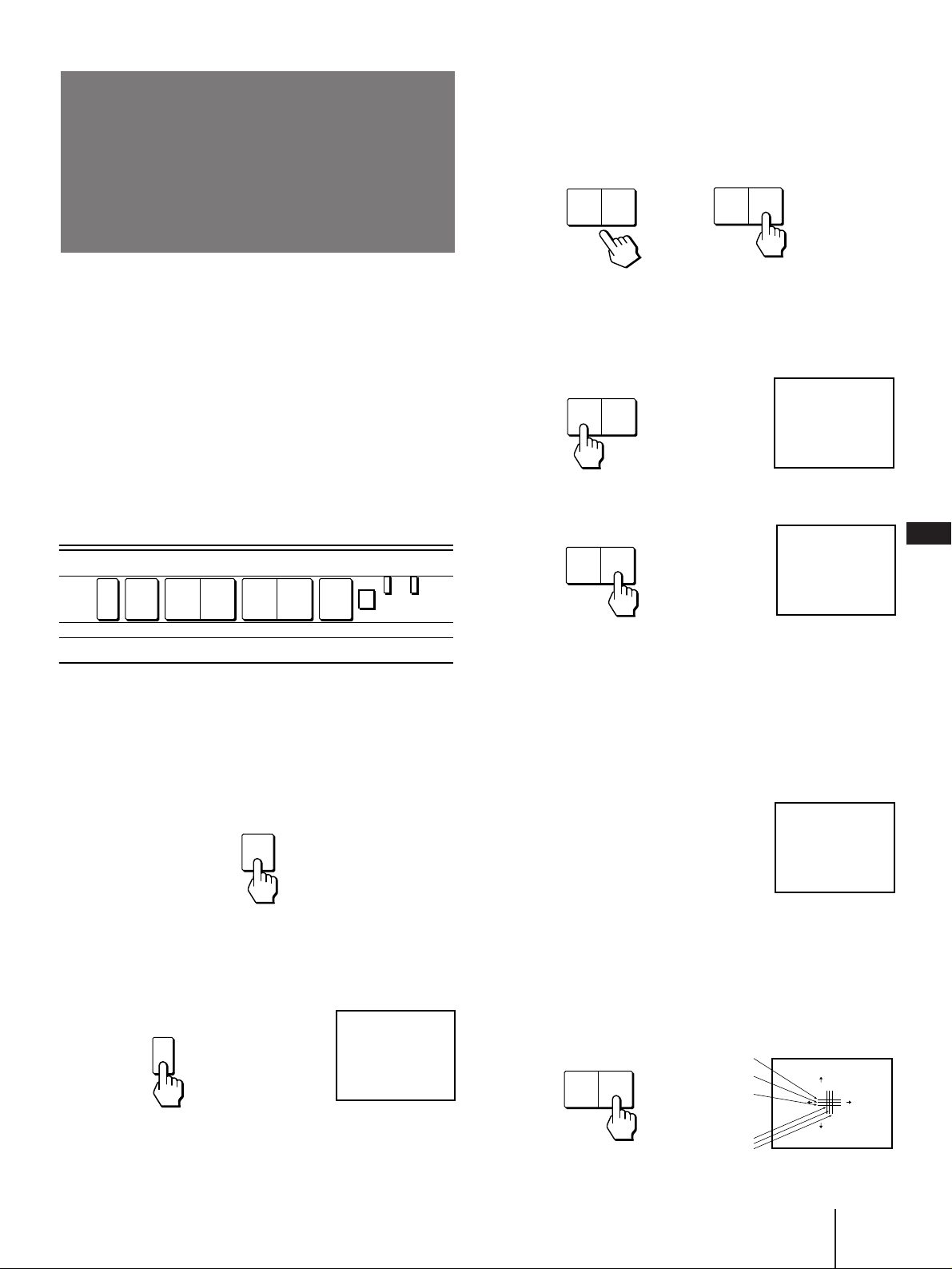
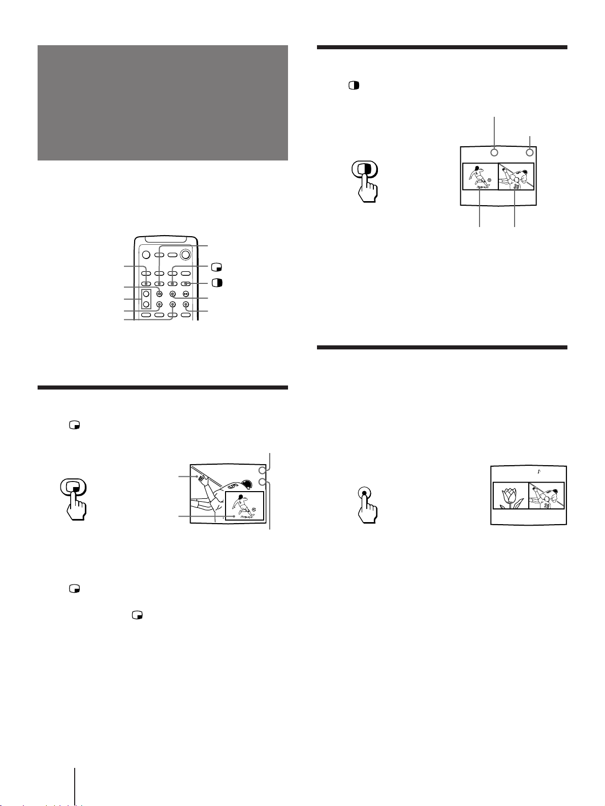
Displaying a window picture (PIP)
Press .
Press repeatedly to display a smaller
window picture.
Each time you press , the size of the window picture
changes as follows: 1/4 size n 1/9 size n 1/16 size.
To remove the window picture, press PIP OFF.
Displaying a left picture (P&P)
Press .
To restore the normal picture, press PIP OFF.
Notes
• If the main/right picture is not receiving an image, the
window/left picture may become a noisy picture.
• The window/left picture sound is also output from the
AUDIO (VAR/FIX) OUT jacks when you listen to it.
Changing the window/left picture
input mode
Press TV/VIDEO (yellow labelled button) in PIP
or P&P mode to select the input mode.
Each time you press TV/VIDEO (yellow labelled
button), “TV”, “VIDEO 1”, “VIDEO 2”, “VIDEO 3”,
and “VIDEO 4” appear in sequence.
A window/left picture will appear in the same input
mode as the last time you used PIP.
Notes
• If you connect your VCR without a cable box, your PIP input
source is a VCR. If you connect your VCR with a cable box,
your PIP input source is a VCR or cable box.
• When the video label for VIDEO 4 is set to SKIP, “VIDEO
4”does not appear on the display.
TV/VIDEO
1 6
67
Watching two
programs at one
time — PIP/P&P
(Twin View™)/CH INDEX
SWAP
TV/VIDEO (yellow
labelled button)
PIP OFF
FREEZE
Left picture Right picture
Input-source mode or TV
channel for the left picture
Input-source mode
or TV channel for
the right picture
Input-source mode or TV
channel for the window picture
Input-source mode or TV
channel for the main picture
Main picture
Window picture
(1/4 size)
CH +/– (yellow
labelled button)
POSITION
AUDIO
6
7
CH INDEX
29
-EN
Operations
EN
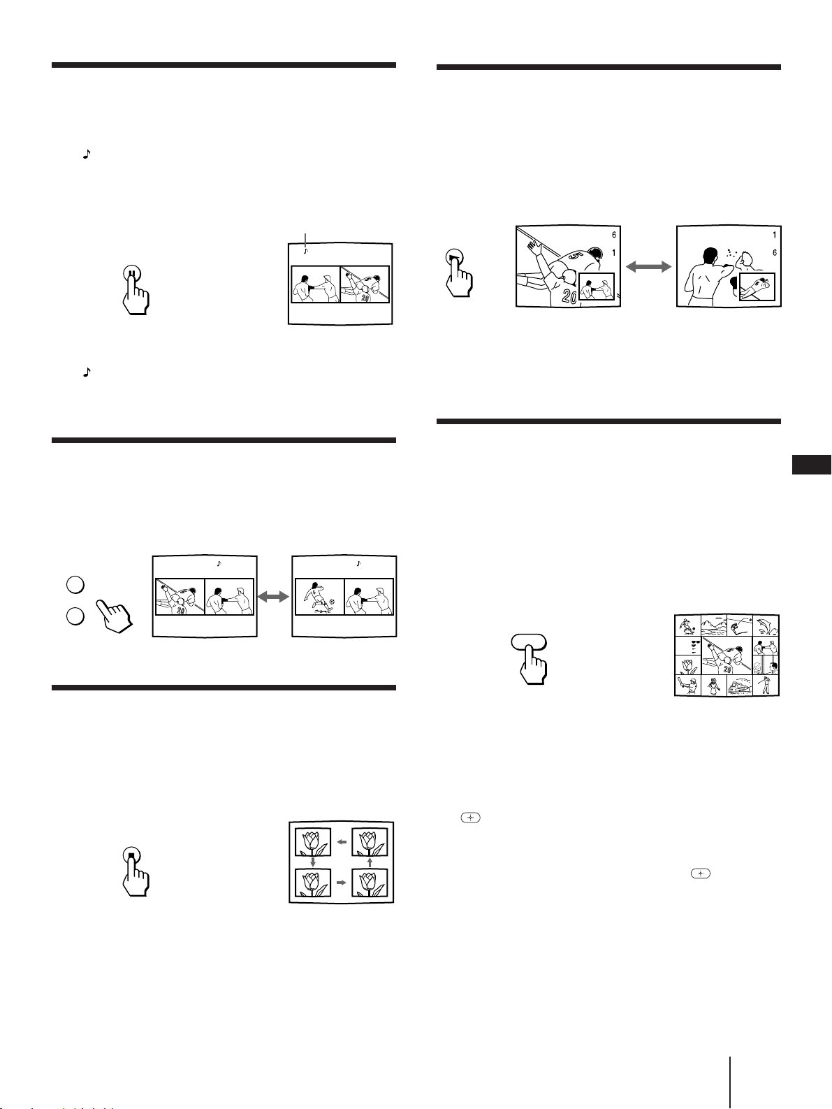
Swapping the main/right and window/
left pictures
Press SWAP in PIP or P&P mode.
Each time you press SWAP, the images and sound
from the main/right and window/left pictures switch
places with another.
Note
• The channels being received through the AUX connector
cannot be displayed as a window picture.
Watching multiple TV channels at one
time (CH INDEX)
You can display all the preset channels in sequence.
1 Press CH INDEX.
The main picture is displayed in the center with a
pink frame and 12 window pictures are displayed
around the main picture.
Each time you press CH INDEX, the 12 window
pictures will rotate and a new picture will appear.
2 Press V, B, v or b to move the pink frame to
the channel you want to watch, and press
.
The selected channel appears on the screen.
To display eight favorite channels, press .
To return to the normal picture, press PIP OFF.
Listening to the sound of the window/
left picture
Press AUDIO in PIP or P&P mode.
The display appears above the window/left picture
for a few seconds, indicating that the window/left
picture sound is being received.
To restore the main picture sound, press AUDIO again.
The display moves to the main picture channel
number.
Changing TV channels in the window/
left picture
Press CH +/– (yellow labelled button) in PIP or
P&P mode.
Changing the position of the window
picture
Press POSITION in PIP mode.
Each time you press POSITION, the window picture
will move counterclockwise on the screen.
SWAP
POSITION
CH
–
+
TV/VTR
AUDIO
CH INDEX
6 1 7 1
1 6
The sound of the window
picture is received.
6
Recipe
flour - - - - 2
sugar - - - 1/2
salt - - - - - 1/2
butter - - - 1
30
-EN
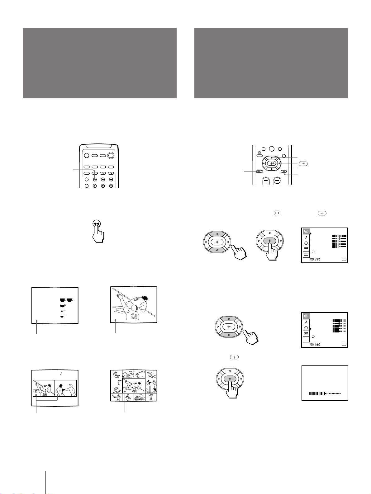
Operations
The FREEZE feature is useful when you want to write
down an information such as a recipe from a cooking
program, a displayed address, or a phone number.
Press FREEZE.
The frozen picture differs depending on the current
display mode.
To cancel the frozen picture, press FREEZE again.
VIDEO STANDARD
BRIGHTNESS
When watching TV programs, you can adjust the
picture to suit your taste.
You can adjust the picture of video input(s) as well.
1 Press MENU.
2 Press V or v to select , and press .
3 Select the item you want to adjust.
For example:
(1) To adjust the brightness, press V or v to move
the cursor (z) to BRIGHTNESS.
(2) Press .
VIDEO
MODE : STANDARD
PICTURE
HUE
COLOR
BRIGHTNESS
SHARPNESS
CC
TRINITONE : HIGH
MENU
Use
Exit
MENU
VIDEO
MODE : STANDARD
PICTURE
HUE
COLOR
BRIGHTNESS
SHARPNESS
CC
TRINITONE : HIGH
MENU
Use
Exit
MENU
7 8
0
9
FREEZE
Freezing the picture
(FREEZE)
FREEZE
Adjusting the
picture
(VIDEO)
V
v
MENU
RESET
Recipe
flour - - - - 2
sugar - - - 1/2
salt - - - - - 1/2
butter - - - 1
6 VIDEO 1
Reciipe
flour - - - - 2
sugar - - - 1/2
salt - - - - - 1/2
butter - - - 1
6
Normal mode PIP mode
The current picture freezes.
The main picture freezes and
the window picture
disappears.
P&P mode
CH INDEX mode
Only the main picture
freezes.
Both pictures freeze.
 Loading...