


KP-51PX3
KP-44PX3
RM-945
R
SERVICE MANUAL AE-6Y CHASSIS
MODEL
KP-51PX3
SECTION 4. SET-UP ADJUSTMENTS
COMMANDER DEST CHASSIS NO.
RM-943 AEP SCC-Q85J-A
MODEL
SUPPLEMENT - 1
SUBJECT : CHANGES TO ADJUSTMENTS
In order to improve the adjustment of the TV set, some
changes to the adjustment sections have been made.
COMMANDER DEST CHASSIS NO.
4-3. SCREEN (G2) ADJUSTMENT (Page 21) .............See page 2
4-5. 2-POLE MAGNET ADJUSTMENT (Page 22) .............See page 3
4-6. 4-POLE MAGNET ADJUSTMENT (Page 22) .............See page 3
SECTION 5. SAFETY RELATED ADJUSTMENT
5-1. HV HOLD-DOWN ADJUSTMENT (Page 23) .............See page 4
SECTION 6. ELECTRICAL ADJUSTMENTS
6-2-4. PROJECTOR ENGINE ADJUSTMENT (Page 30) .............See pages 5 & 6
(SUBDEFLECTION ADJUSTMENT)
9-927-459-81
Sony Corporation
Sony UK
Service Promotions Dept
- 1 -
English
04FP7100-1
© 2004.06
SECTION 4 SET-UP ADJUSTMENTS
KP-51PX3
RM-945
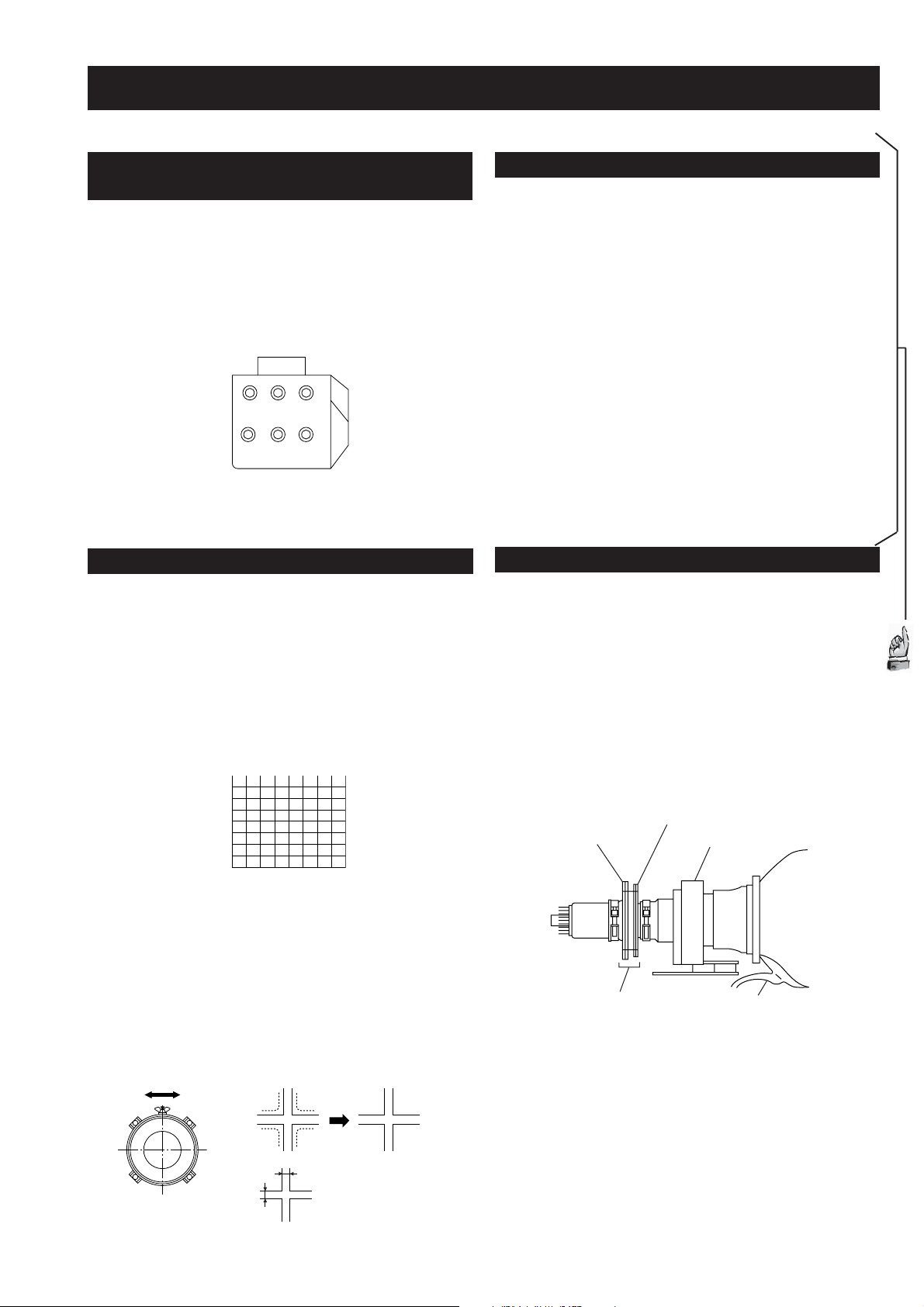
4-1. SCREEN VOLTAGE ADJUSTMENT
(ROUGH ALIGNMENT)
1. Receive the Monoscope signal.
2. Set 50% BRIGHTNESS and minimum PICTURE.
3. Turn the red VR on the focus pack all the way to the left
and then gradually turn it to the right until the point where
you can see the retrace line.
4. Next gradually turn it to the left to the position where the
retrace line disappears.
RG
RG
B
SCREEN
B
FOCUS
Focus Pack
Fig. 4-1
4-2. FOCUS ROUGH ADJUSTMENT
1. Loose the lens screw.
2. Program Remote Commander for operation in Service
mode (See Page 23).
3. Place the caps on the red and blue lens so that only the
green color is shown.
4. Press “VIDEO” “VIDEO” “5” “6” on the remote
commander to enter 'Projector Engine'. Press “6” twice
on the Commander to display the test signal (crosshatch)
on the screen.
4-3. SCREEN (G2) ADJUSTMENT
1. Turn on the power of the set.
2. Program the remote commander for operation in Service mode.
(See Service Manual page 24).
3. Select VIDEO1 mode without signals.
4. Press the "audio/video" standby button twice then 38 on remote
commander to enter adjustment mode (picture will not be visible).
5. Supply DC 177.5 ±0.5 V from external power supply to
TP9000 (KR) of CR board.
6. Turn G2 VR counterclockwise until set retrace line just
disappears.
7. Supply DC 174 ±0.5 V from external power supply to
TP9000 (KR) of CR board.
8. Confirm that retrace can be seen.
9. Repeat from step 5 to adjust green (KG on CG board) and blue
(KB on CB board) screen voltages.
10. Press 00 to exit adjustment mode.
Important: DC power supply must have a DC load to supply
100mA. Connect a 1k8 18W resistor between power
supply terminals.
4-4. DEFLECTION YOKE TILT ADJUSTMENT
1. Receive the Monoscope signal.
2. Place the caps on the red and blue lens so that only the
green color is shown.
3. Loosen the deflection yoke set screw and align the tilt of
the Deflection yoke so that the bars at the center of
the monoscope pattern are horizontal.
4. After aligning the deflection yoke, fasten it securely to
the funnel-shaped portion (neck) of the CRT.
Amended
Section
5. The tilt of the deflection yoke for red and blue is aligned
the same as was done for green.
Test signal
Fig. 4-2
5. Rotate the green lens and align to obtain the best lens
focus at the center area.
6. Rotate the green focus VR on the focus pack and align to
obtain the best electrical focus at the centre area.
7. Perform the same alignment for red and blue lenses and
electric focus.
8. Fix lens screw.
A
Minimize both A and B.
Lens
Fig. 4-3
B
Fig. 4-4
4-pole magnet
2-pole magnet
Neck Assy
Make sure deflection yoke is
touching CRT closely.
Fig. 4-5
Deflection yoke
Anode cap
- 2 -
 Loading...