


 Loading...
HISTORY
Model Name: KLV-26/32NX400
KLV-32/40NX500
|
|
SERVICE MANUAL |
|
|
Click on Page Number to display details of change |
|
|||
|
|
|
|
|
Date |
Part Number |
Description of Revisions |
|
Version |
2010.06 |
9-883-489-01 |
Original Manual |
|
1.0 |
|
|
|
|
|
2010.08 |
9-883-489-02 |
LCD Panel Part Number Update (P18) |
|
2.0 |
BAA Board Part Number Update (P18) |
|
|||
|
|
|
|
|
2010.08 |
9-883-489-03 |
Addition of Panel Support Part Number (P17, 18, |
|
3.0 |
19) |
|
|||
|
|
|
|
|
|
|
|
|
|
|
|
|
|
|
|
|
|
|
|
|
|
|
|
|
|
|
|
|
|
|
|
|
|
|
|
|
|
|
|
|
|
|
|
|
|
|
|
|
|
|
|
|
|
|
|
|
|
|
|
|
|
|
|
|
|
|
|
|
|
|
|
|
|
|
|
|
|
|
|
|
|
|
|
|
|
|
|
|
|
|
|
|
|
|
|
|
|
|
|
|
|
|
|
|
|
|
|
|
|
|
|
|
|
|

SERVICE MANUAL |
AZ1-A(5-0) CHASSIS |
MODEL
DEST MODEL
DEST
KLV-26NX400 KLV-32NX400
(black / silver) |
RUSS |
(black / silver) |
RUSS |
KLV-32NX500 KLV-40NX500
RUSS
RUSS
RM-GA018
- -
KLV-26,32 NX400(S/B), 26,32 NX400(S/B)/S, 32,40 NX500 |
|
|
|
|
|
|
||||||
|
|
|
|
RM-GA018 |
|
|
|
|
|
|
||
|
|
|
TABLE OF CONTENTS |
|
|
|
|
|||||
|
Section Title |
|
Page |
Section Title |
|
Page |
||||||
1. |
SAFETY NOTES |
|
|
|
5. |
DIAGRAMS |
|
|
|
|||
|
|
1-1. Caution Handling of LCD Panel ..................................... |
3 |
|
5-1. Block Diagram ............................................................... |
11 |
||||||
|
|
1-2. Safety Check Out ............................................................. |
3 |
|
5-1-1. |
KLV-32,40 NX500 ............................................. |
11 |
|||||
|
|
1-3. Leakage Test .................................................................... |
3 |
|
5-1-2. |
KLV-26,32 NX400(S/B), |
|
|
||||
|
|
1-4. WARNING ! .................................................................... |
3 |
|
|
26,32 NX400(S/B)/S ......................................... |
12 |
|||||
|
|
1-5. Lead Free Information ..................................................... |
4 |
|
5-2. Wire Dressing and Connector Diagram ....................... |
13 |
||||||
|
|
|
|
|
|
|
|
5-2-1. |
KLV-26 NX400(S/B), NX400(S/B)/S ............... |
13 |
||
|
|
|
|
|
|
|
|
5-2-2. KLV-32 NX400(S/B),NX400(S/B)/S, NX500 .. |
14 |
|||
2. |
SELF DIAGNOSTIC FUNCTION |
|
|
|
|
5-2-3. KLV-40NX500 ................................................... |
15 |
|||||
|
|
2-1. Overview of Control Buttons .......................................... |
5 |
|
5-3. Circuit Board Location .................................................. |
16 |
||||||
|
|
2-2. LED Display Specification .............................................. |
5 |
|
5-3-1. |
KLV-26 NX400(S/B), NX400(S/B)/S ............... |
16 |
|||||
|
|
2-3. LED Display Control ....................................................... |
5 |
|
5-3-2. |
KLV-32 NX400(S/B),NX400(S/B)/S, NX500 .. |
16 |
|||||
|
|
2-4. LED Pattern ..................................................................... |
5 |
|
5-3-3. KLV-40NX500 ................................................... |
16 |
||||||
|
|
2-5. Standby LED Error Display and Board |
|
|
|
|
|
|
|
|
|
|
|
|
Replacement Order .......................................................... |
6 |
|
|
|
|
|
|
|||
|
|
2-6. Triage Chart ..................................................................... |
7 |
6. |
DISASSEMBLY, EXPLODED VIEWS AND |
|
|
|||||
|
|
|
|
|
|
|
|
OTHER PARTS |
|
|
||
|
|
|
|
|
|
|
|
6-1. Disassembly & Exploded Views ................................... |
17 |
|||
3. |
TROUBLE SHOOTING |
|
|
|
|
6-1-1. KLV-26 NX400(S/B), NX400(S/B)/S ................ |
17 |
|||||
|
|
3-1. Flowchart ......................................................................... |
8 |
|
6-1-2. KLV-32 NX400(S/B), NX400(S/B)/S, NX500 .. |
18 |
||||||
|
|
3-1-1. No Power ....................................................................... |
8 |
|
6-1-3. KLV-40NX500 .................................................... |
19 |
||||||
|
|
3-1-2. Video Problem ............................................................... |
9 |
|
6-2. Other Parts ..................................................................... |
20 |
||||||
|
|
3-1-3. Audio Problem .............................................................. |
9 |
|
6-2-1. KLV-26 NX400(S/B), NX400(S/B)/S ................ |
20 |
||||||
|
|
|
|
|
|
|
|
6-2-2. KLV-32 NX400(S/B), NX400(S/B)/S, NX500 .. |
20 |
|||
|
|
|
|
|
|
|
|
6-2-3. KLV-40NX500 .................................................... |
21 |
|||
4. |
SERVICE ADJUSTMENTS |
|
|
|
|
|
|
|
|
|
||
|
|
4-1. Accessing Self Diagnostic Menu .................................. |
10 |
|
|
|
|
|
|
|||
|
|
4-2. Accessing Service Mode ............................................... |
10 |
|
OPERATING INSTRUCTIONS |
|
|
|||||
|
|
4-3. GAISOU Adjustment(For Board Replacement) ........... |
10 |
|
|
|
|
|
|
|||
– 2 –
|
|
KLV-26,32 NX400(S/B), 26,32 NX400(S/B)/S, 32,40 NX500 |
||
|
SECTION 1 |
RM-GA018 |
||
|
SAFETY NOTES |
|
||
1-1. Caution Handling of LCD Panel |
1-3. Leakage Test |
|
|
|
When installing the LCD Panel, make sure you are grounded |
The AC leakage from any exposed metal part to earth |
|
||
with a wrist band. |
ground and from all exposed metal parts to any exposed |
|
||
When installing the LCD Panel on the wall, the panel must be |
metal part having a return to chassis must not exceed 0.5mA |
|||
secured using the 4 mounting holes on the rear cover. |
(500 microamperes). Leakage current can be measured by |
|||
1) |
Do not press the panel or frame edge to avoid the risk of |
any one of the three methods:- |
|
|
electric shock. |
1. A commercial leakage tester such as the SIMPSON 229 or |
|||
2) |
Do not scratch or press on the panel with any sharp |
RCA WT-540A. Follow the manufacturers instructions to use |
||
objects. |
those instructions. |
|
||
3) |
Do not leave the module in high temperature or in areas of |
2. A battery-operated AC milliampmeter. The DATA |
|
|
high humidity for an extended period of time. |
PRECISION 245 digital multimeter is suitable for this job. |
|
||
4) |
Do not expose the LCD panel to direct sunlight. |
3. Measuring the voltage drop across a resistor by means of |
||
5) |
Avoid contact with water. It may cause short circuit within |
a VOM or battery operated AC voltmeter. The 'limit' indication |
||
the module. |
is 0.75V so analog meters must have an accurate low voltage |
|||
6) |
Disconnect the AC Power when replacing the backlight |
scale. The SIMPSON'S 250 and SANWA SH-63TRD are |
|
|
(CCFL) or inverter circuit. (High voltage occurs at the inverter |
examples of passive VOMs that are suitable. Nearly all battery |
|||
circuit at 650Vrms) |
operated digital multimeters that have a 2 VAC range are |
|
||
7) |
Always clean the LCD panel with a soft cloth material. |
suitable. (see Figure 1.) |
|
|
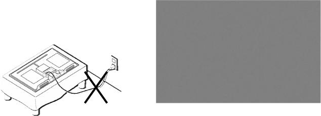
8)Use care when handling the wires or connectors of the inverter circuit. Damaging the wires may cause a short circuit.
9)Protect the panel from ESD to avoid damaging the electronic circuit (C-MOS).
10)During the repair, DO NOT leave the Power On
for more than 1 hour while the TV is face down on a cloth.
|
> 1 hour |
|
Figure 1. AC voltmeter to check AC leakage |
|
|
|
|
||
|
|
|
1-4. WARNING ! |
|
1-2. Safety Check-Out |
||||
SAFETY-RELATED COMPONENT WARNING! |
||||
After correcting the original service problem, perform the |
||||
COMPONENTS IDENTIFIED BY SHADING AND MARK ! |
||||
following safety checks before releasing the set to the |
||||
ON THE EXPLODED VIEWS ARE CRITICAL FOR SAFE |
||||
customer:- |
||||
OPERATION. REPLACE THESE COMPONENTS WITH |
||||
1) Check the area of your repair for unsoldered or poorly |
||||
SONY PARTS WHOSE PART NUMBERS APPEAR AS |
||||
soldered connections. Check the entire board surface for |
||||
SHOWN IN THIS MANUAL OR IN SUPPLEMENTS |
||||
solder splashes and bridges. |
||||
PUBLISHED BY SONY. CIRCUIT ADJUSTMENTS THAT ARE |
||||
2) Check the interboard wiring to ensure that no wires are |
||||
CRITICAL FOR SAFE OPERATION ARE IDENTIFIED IN |
||||
"pinched" or contact high-wattage resistors. |
||||
THIS MANUAL. FOLLOW THESE PROCEDURES |
||||
3)Check all control knobs, shields, covers, ground straps and |
||||
WHENEVER CRITICAL COMPONENTS ARE REPLACED |
||||
mounting hardware have been replaced. Be absolutely certain |
||||
OR IMPROPER OPERATION IS SUSPECTED. |
||||
you have replaced all the insulators. |
||||
|
||||
4) Look for unauthorized replacement parts, particularly |
|
|||
transistors that were installed during a previous repair. Point |
|
|||
them out to the customer and recommend their replacement. |
|
|||
5) Look for parts which, though functioning show obvious |
|
|||
signs of deterioration. Point them out to the customer and |
|
|||
recommend their replacement. |
|
|||
6) Check the line cords for cracks and abrasion. |
|
|||
Recommend the replacement of any such line cord to the |
|
|||
customer. |
|
|||
7) Check the antenna terminals, metal trim, "metallized" |
|
|||
knobs, screws and all other exposed metal parts for AC |
|
|||
leakage. Check leakage test as described next. |
|
|||
8) Live chassis can cause electric shock as its |
|
|||
connected to the AC power line. Therefore, use |
|
|||
isolation transformer and gloves when changing parts |
|
|||
or removing plug. Please remember high voltage is |
|
|||
there during servicing. |
|
|||
9) To follow safety after servicing, please make sure |
|
|||
the removed screws, parts and wires are as original |
|
|||
condition. |
|
|||

KLV-26,32 NX400(S/B), 26,32 NX400(S/B)/S, 32,40 NX500
RM-GA018
1-5. Lead Free Information
The circuit boards used in these models have been processed using Lead Free Solder. The boards are identified by the LF logo located close to the board designation.
Figure 2: LF logo
Figure 3: LF logo on circuit board
The servicing of these boards requires special precautions. It is strongly recommended to use Lead Free Solder material in order to guarantee optimal quality of new solder joints. Lead Free Solder is available under the following part numbers:-
Part number |
Diameter |
Remarks |
7-640-005-19 |
0.3mm |
0.25Kg |
7-640-005-20 |
0.4mm |
0.50Kg |
7-640-005-21 |
0.5mm |
0.50Kg |
7-640-005-22 |
0.6mm |
0.25Kg |
7-640-005-23 |
0.8mm |
1.00Kg |
7-640-005-24 |
1.0mm |
1.00Kg |
7-640-005-25 |
1.2mm |
1.00Kg |
|
|
|
7-640-005-26 |
1.6mm |
1.00Kg |
Due to high melting point of Lead Free Solder, the soldering iron tip temperature needs to be set to 370 degrees centigrade. This requires soldering equipment capable of accurate temperature control coupled with a good heat recovery characteristics.
For more information on the use of Lead Free Solder, please refer to http://www.sony-training.com
– 4 –
KLV-26,32 NX400(S/B), 26,32 NX400(S/B)/S, 32,40 NX500
RM-GA018
SECTION 2
SELF DIAGNOSTIC FUNCTION
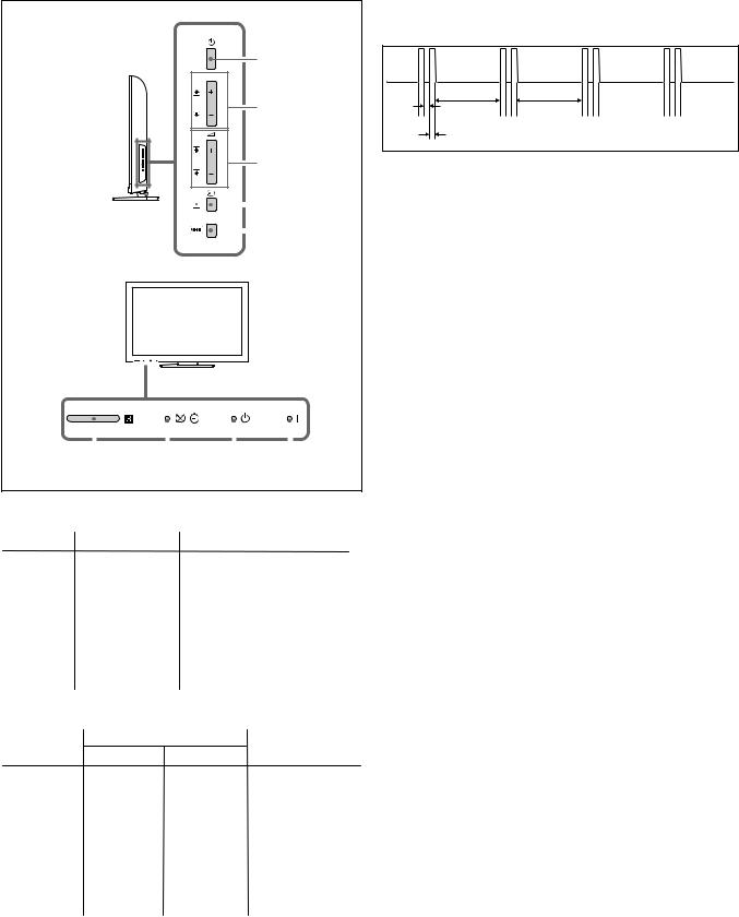
2-1. Overview of Control Buttons |
|
2-4. LED Pattern |
|
|
|
When safety shutdown occurs, Standby LED display reports the |
|
|
|
cause by using the lightning patterns as indicated below. |
|
|
Power |
|
|
PROG |
|
|
|
|
Programme |
3.0 sec |
3.0 sec |
|
|
||
|
|
0.5 sec |
|
|
|
0.5 sec |
|
|
Volume |
|
|
|
|
|
|
|
|
|
|
|
|
|
|
|
|
Input select/ |
Example: |
|||
|
|
|
|
|
|
|
|
|
|
|
|
|
|
|||||
|
|
|
|
|
|
|
|
|
|
|
|
|
|
|||||
|
|
|
|
|
|
|
|
|
|
|
|
|
|
The figure above shows LED display when |
||||
|
|
|
|
|
|
|
|
|
|
|
|
|
|
|||||
|
|
|
|
|
|
|
|
|
|
|
|
|
|
Enter |
||||
|
|
|
|
|
|
|
|
|
|
|
|
|
|
Menu |
SHUTDOWN is caused by Balancer Error. It repeats |
|||
|
|
|
|
|
|
|
|
|
|
|
|
|
|
|||||
|
|
|
|
|
|
|
|
|
|
|
|
|
|
|
|
|
|
flashing for a specified number of times in 0.5sec/ |
|
|
|
|
|
|
|
|
|
|
|
|
|
|
|
|
|
|
cycle and has a 3 seconds interval of lighting off. |
|
|
|
|
|
|
|
|
|
|
|
|
|
|
|
|
|
|
Please note that a 3 seconds interval of lighting off |
|
|
|
|
|
|
|
|
|
|
|
|
|
|
|
|
|
|
is fixed regardless of abnormal state types. |
|
|
|
|
|
|
|
|
|
|
|
|
|
|
|
|
|
|
|
|
|
|
|
|
|
|
|
|
|
|
|
|
|
|
|
|
|
|
|
|
|
|
|
|
|
|
|
|
|
|
|
|
|
|
|
|
|
|
|
|
|
|
|
|
|
|
|
|
|
|
|
|
|
|
|
|
|
|
|
|
|
|
|
|
|
|
|
|
|
|
|
|
|
|
|
|
|
|
|
|
|
|
|
|
|
|
|
|
|
|
|
|
|
|
|
|
|
|
|
|
|
|
|
|
|
|
|
|
|
|
|
|
|
Remote |
Picture Off/ |
Standby |
Power |
Sensor |
Timer indicator |
indicator |
indicator |
2-2. LED Display Specification |
|
|
|||
|
|
|
|
||
LEDType |
Description |
Remark |
|
||
POWER |
Green: LED |
Green lights at power ON. |
|
||
|
|
|
|
||
STANDBY |
Red:One LED |
Red lights during standby. |
|
||
|
|
|
|
||
Timer |
Orange |
Orange lights |
|
||
|
:One LED |
duringTimer activation. |
|
||
|
|
|
|
||
2-3. LED Display Control |
|
|
|
||
|
|
|
|
||
Status |
Display |
Remark |
|||
Power LED |
Standby LED |
||||
|
|
|
|||
POWER ON |
Green lights |
OFF |
Microcomputer is |
||
in a normal state. |
|||||
|
|
|
|||
|
|
|
|
||
STANDBY |
OFF |
Red lights |
Microcomputer is |
||
|
|
|
in a sleep state. |
||
|
|
|
|
||
Failure |
OFF |
Red flashes |
Classify the trouble |
||
causes by the no. |
|||||
|
|
|
|||
|
|
|
of red blinking. |
||
|
|
|
|
|
|
– 5 –
KLV-26,32 NX400(S/B), 26,32 NX400(S/B)/S, 32,40 NX500
RM-GA018
2-5. Standby LED Error Display and Board Replacement Order
Perform below countermeasures according to Standby LED blinking times.
Blinking times |
Error |
|
Countermeasure |
|
|
(Replace either/all according to sequence) |
|
|
|
|
|
2 |
Main Power Error |
1) Power Unit(26”), G2LE Unit(32”), |
|
|
|
|
G2HE Unit(40”) board. |
|
|
2) |
BAA board. |
|
|
|
|
3 |
DC_ALERT 1/ Audio Error/ |
1) BAA board. |
|
|
Motionflow Error |
2) Power Unit(26”), G2LE Unit(32”), |
|
|
|
|
G2HE Unit(40”) board. |
|
|
3) TCON. |
|
|
|
4) Speaker. |
|
|
|
|
|
4 |
Balancer Error |
1) Inverter board. |
|
|
|
2) |
Panel. |
|
|
3) |
Power Unit(26”), G2LE Unit(32”), |
|
|
|
G2HE Unit(40”) board. |
|
|
4) |
BAA board. |
|
|
|
|
5 |
T-CON Error / Panel ID NVM Error |
1) T-CON. |
|
|
|
2) |
BAA board. |
|
|
3) |
LVDS Cable. |
|
|
4) |
Power Unit(26”), G2LE Unit(32”), |
|
|
|
G2HE Unit(40”) board. |
|
|
|
|
6 |
Backlight Error |
1) Inverter board |
|
|
|
2) |
Power Unit(26”), G2LE Unit(32”), |
|
|
|
G2HE Unit(40”) board. |
|
|
3) |
BAA board. |
|
|
|
|
7 |
Temp. Error |
1) BAA board. |
|
|
|
2) |
Power Unit(26”), G2LE Unit(32”), |
|
|
|
G2HE Unit(40”) board. |
|
|
|
|
Note:- |
|
|
|
1: Each of the above blinking repeats 3 seconds. |
|
|
|
2. Countermeasure is list out by priority. |
|
|
|
– 6 –

KLV-26,32 NX400(S/B), 26,32 NX400(S/B)/S, 32,40 NX500
RM-GA018
2-6. Triage Chart
|
NoAudio |
|
|
BAAboard |
|
NoHDMI |
|
|
BAAboard |
distoredormissing |
NoTuner TunerOK |
VideoOK Video1-3 |
Bad |
BAAboard BAAboard |
Video |
NoVideo |
BLOK |
NoOSD |
BAAboard |
|
NoVideo |
NoBL |
|
BAAboard |
|
NoVideo |
BLOK |
OSDOK |
BAAboard |
|
|
NoPower |
|
NoPower |
|
|
7Blinks |
|
Temperature |
set) |
|
6Blinks |
|
ID Inverter |
Symptom(dead |
|
4Blinks 5Blinks |
|
Balancer TCON,Panel |
|
|
3Blinks |
|
BAAboard |
|
|
2Blinks |
|
NoPower |
|
Reference |
|
BAAboard H2LRboard H2LS HLR3board SW1board PowerUnit(26") G2LEUnit(32") G2HEUnit(40") T-conboard Speakerunit RFmodule Panelmodule FFCcable Jointconnector Problem |
|
Few possibility
Doubtful part
– 7 –
KLV-26,32 NX400(S/B), 26,32 NX400(S/B)/S, 32,40 NX500
RM-GA018
SECTION 3
TROUBLESHOOTING
3.1 FLOWCHART
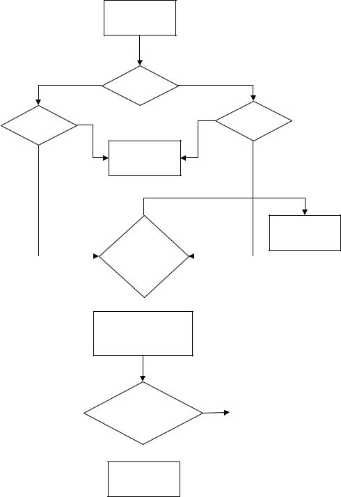
3-1-1. NO POWER
No power
110V
Destination
No
88-132Vac
AC Cable
Yes
No
3.3V_DC
C16200 Pin3 on BAA board
 Yes
Yes
3.3V_DC
C16200 Pin3 on BAA board
12.5V_DC
C16200 Pin10 on BAA board
 Yes
Yes
BAA Board
220V-240V
No
176-264Vac
Yes
Power Board
No standby3.3V
No |
Power Board |
|
No REG12V |
|
|
– 8 –
KLV-26,32 NX400(S/B), 26,32 NX400(S/B)/S, 32,40 NX500
RM-GA018
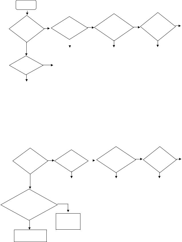
3-1-2. VIDEO PROBLEM
Video
Problem
All inputs |
No |
|
HDMI |
No |
RF/Analog |
No |
Digital |
No |
BAA |
|||
|
Input |
|||||||||||
|
|
Input |
|
Board |
||||||||
have |
|
|
Problem? |
|
|
|
|
|||||
|
|
|
|
|
Problem? |
|
||||||
|
|
|
|
|
|
|
||||||
|
|
|
|
Problem? |
|
|
|
|||||
problem? |
|
|
|
|
|
|
|
|
|
|
||
|
|
|
|
|
|
|
|
|
|
|
||
|
|
|
|
|
|
|
|
|
|
|
|
|
Yes |
|
|
|
|
|
|
|
Yes |
|
Yes |
|
|
|
|
|
|
|
|
|
|
|
|
|
|
|
|
|
|
|
BAA |
|
|
BAA |
|
BAA |
|
|
|
|
|
|
|
Board |
|
|
Board |
|
Board |
|
|
|
Backlight |
Yes |
|
|
|
|
|
|
|
|
|
|
|
BAA |
|
|
|
|
|
|
|
|
||||
Turn on? |
|
|
|
|
|
|
|
|
|
|
||
|
|
Board |
|
|
|
|
|
|
|
|
||
|
|
|
|
|
|
|
|
|
|
|
||
No |
|
|
|
|
|
|
|
|
|
|
|
|
|
|
|
|
|
|
|
|
|
|
|
|
|
|
|
|
|
|
|
|
|
|
|
|
|
|
Check LVDS harness |
|
|
|
|
|
|
|
|
|
|
|
|
connection |
|
|
|
|
|
|
|
|
|
|
|
|
between BAA board or |
|
|
|
|
|
|
|
|
|
|
|
|
Panel or Power board |
|
|
|
|
|
|
|
|
|
|
|
|
|
|
|
|
|
|
|
|
|
|
|
|
|
3-1-3. AUDIO PROBLEM
Only |
No |
HDMI |
No |
RF/ Analog |
No |
Digital |
No |
BAA |
|
|
Input |
|
Input |
|
|||||
Speaker |
|
Problem? |
|
|
|
|
Board |
||
|
|
|
Problem? |
|
Problem? |
|
|||
out? |
|
|
|
|
|
|
|
||
|
|
|
|
|
|
|
|
|
|
Yes |
|
|
|
|
|
|
|
|
|
|
BAA |
|
|
BAA |
|
BAA |
|
|
|
|
|
|
|
|
|
|
|||
|
|
Board |
|
|
Board |
|
Board |
|
|
|
|
|
|
|
|
|
|
|
|
UI of
Audio Setting Yes correct? Volume,
TV Speaker
Check
No Speaker
BAA board
Set correctly or reset by menu
– 9 –
KLV-26,32 NX400(S/B), 26,32 NX400(S/B)/S, 32,40 NX500
RM-GA018
SECTION 4
SERVICE ADJUSTMENT
4-1. Accessing Self Diagnostic Menu
1.While TV on standby mode, press the following sequence on the Remote commander.
< Display--> <5>--> <Vol Down>--> <Power>
|
Self Check |
|
|
|
|
|
indicates no. of times an error |
||||||
|
002 |
|
|
|
Main Power |
001 |
|||||||
|
|
|
|
was detected. |
|||||||||
|
003 |
|
|
|
Dc_Alert |
|
000 |
0 indicates no error was detected |
|||||
|
|
|
|
|
|
||||||||
|
003 |
|
|
|
Aud_Prot |
|
000 |
|
|||||
|
003 |
|
|
|
MotionFlow |
|
000 |
|
|||||
|
004 |
|
|
|
Balancer_Error |
|
000 |
|
|||||
|
005 |
|
|
|
T-CON Error |
|
|
|
|||||
|
005 |
|
|
|
Panel ID NVM Error |
|
000 |
|
|||||
|
006 |
|
|
|
Backlight Error |
|
000 |
|
|||||
|
007 |
|
|
|
Temp_Error |
|
000 |
|
|||||
|
|
|
00027 |
|
00009 |
|
|
|
Diagnostic Menu Sample |
||||
|
|
|
|
|
|
|
|||||||
|
|
|
|
|
|
|
|||||||
|
00009 |
|
|
|
|
|
|||||||
|
|
|
|
|
|
|
|
|
|
|
|
|
|
|
|
|
|
|
|
|
|
|
|
|
|
|
|
|
|
|
|
|
|
|
|
|
|
|
|
|
|
|
|
|
|
|
|
|
|
|
|
|
|
|
|
|
|
|
|
|
|
|
|
|
Total Panel Hours |
|
|
|
|
|
|
|
|
|
|
|
|
|
(max 65535) |
|
|
|
|
Total Hours |
|
|
|
|
|
|
|
|
|
|
|
||
of Operation |
|
|
|
Boot Count |
|
|
|
|
|||||
(max 65535) |
|
|
|
(max 65535) |
|
|
|
|
|||||
|
|
|
|
|
|
|
|
|
|
|
|
|
|
2. To Reset Error Count & Error History Press < 8 > --> < 0 > key
3. To Reset Panel Operation Time Press < 7 > --> < 0 > key
4. To exit, turn the power off using Remote.
4-2. Accessing Service Mode
1.While TV on standby mode, press the following sequence on the Remote commander.
< Display--> <5>--> <Vol Up>--> <Power>
Tuning System |
<[Auto]> |
No_Signal_Mute |
<[Off]> |
Serial Number Edit |
|
Self Diagnosis History >> |
|
LVDS Spectrum (%) |
<[10]> |
Low of HPD |
<[5]> |
VCR1 |
<[off]> |
GAISOU |
<[0]> |
Service Mode Menu Sample
2.Use the r or R button to select the item you want to refer and press for details.
Example Status information
4-3. GAISOU Adjustment (For Board Replacement)
1)When new board is replaced, please confirm the color ornamental of the TV set.
2)While TV on standby mode, press the following sequence on the Remote commander.
<Display> p <5> p <Vol Up> p <Power>
Tuning System |
|
<[Auto]> |
|
Chassis |
Service |
|
|
No_Signal_Mute |
Model |
<[Off]> |
|
Serial Number Edit |
|
|
|
000 |
|
|
|
Self Diagnosis History >> |
|
|
|
002 |
Gaisou |
00 |
|
LVDS Spectrum (%) |
<[10]> |
|
|
Low of HPD |
|
<[5]> |
|
VCR1 |
|
<[off]> |
|
GAISOU Menu |
Sample |
||
GAISOU |
|
<[0]> |
|
Service Mode Menu Sample
3) Use the r or R button to select the GAISOU item.
Service Mode |
|
Status Information >> |
|
Test Reset |
<[Off]> |
Tuning System |
<[Auto]> |
No_Signal_Mute |
<[Off]> |
Serial Number Edit |
|
Self Diagnosis History >> |
|
LVDS Spectrum (%) |
<[10]> |
Low of HPD |
<[5]> |
VCR1 |
<[off]> |
GAISOU |
<[0]> |
4) The color variation table of each TV set as below:-
Case |
Color |
Model |
Panel ID |
Area |
|
Table |
Type |
Name |
Resolution |
Inch Size |
ID |
00 |
Default |
5-2 |
WXGA/FHD |
40, 32,26, 22 |
ALL |
01 |
Glossy Gun Metallic (back print) |
3a-2 |
FHD |
32,40,46 |
GA |
02 |
Glossy Silver (back print) |
3a-2 |
WXGA |
22,26,32 |
GA |
03 |
Red |
3a-2 |
FHD |
32 |
GA |
04 |
Blue |
3a-2 |
FHD |
32 |
GA |
05 |
Matt Gun Metallic |
3a-2 |
FHD |
32,40,46 |
CH |
06 |
Flat Gun Metallic Hairline |
3a-1, 3a-0.5 |
HFR/ FHD |
32,40,46,55 |
ALL |
07 |
Silver |
5-0 |
FHD |
32,40 |
ALL |
08 |
Black |
5-0 |
WXGA |
26,32 |
ALL |
5)For example if color is Red than should select 03 in the service mode of the TV set.
Service Mode |
|
|
|
|
|
Status Information >> |
|
|
|
Main Micro |
|
Test Reset |
<[Off]> |
|
|
SW Version |
TM0.341.012 |
Tuning System |
<[Auto]> |
|
|
NVM Version |
TD0.341 |
No_Signal_Mute |
<[Off]> |
|
|
Boot Version |
TB0.341 |
Serial Number Edit |
|
|
|
Panel Version |
MT0000.000.0030.LT |
Self Diagnosis History >> |
|
|
|
Flash PQ Version |
|
LVDS Spectrum (%) |
<[10]> |
|
|
AQ Version |
AQ0.003 |
Low of HPD |
<[5]> |
|
|
|
|
|
|
|
|
|
|
|
|
|
|
|
|
– 10 –
|
|
|
|
|
|
|
|
|
|
|
|
|
|
|
KLV-26,32 NX400(S/B), 26,32 NX400(S/B)/S, 32,40 NX500 |
|||||||||||
|
|
|
|
|
|
|
|
|
|
|
|
|
|
|
|
|
|
|
|
|
|
|
|
|
|
RM-GA018 |
|
|
|
|
|
|
|
|
|
|
|
|
SECTION 5 |
|
|
|
|
|
|
|
|
|
|
||||
|
|
|
|
|
|
|
|
|
|
|
|
DIAGRAMS |
|
|
|
|
|
|
|
|
|
|
||||
|
|
|
|
|
|
|
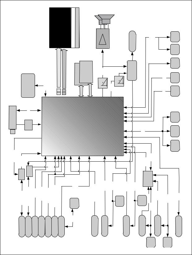
PANEL |
8bit |
(FHD) |
CCFL ConventionalINVERTER |
|
|
|
|
TPA3110D2 |
|
|
HP |
|
STBY UART0 |
|
|
ECS |
|||
|
|
|
|
|
|
|
|
|
|
|
|
|
|
|
|
Hotel UART |
||||||||||
|
|
|
|
|
|
|
|
|
|
OddChannel8bit |
EveChannel8bit |
Memory |
Memory |
DDR2 32Mx16bits |
|
PWM |
|
LPF |
|
NJM2779 |
AMP |
|
|
|
SIRCS LED |
SIRCS LED JTAG |
|
|
NAND FLASH 64MByte |
|
|
PDD0~7 |
|
|
16Bit |
16Bit |
LPF |
PWM |
|
Lineout |
|
|
|
||||||||||
|
|
|
|
|
|
|
|
|
|
ChLVDS |
I/F |
|
|
|
outx2ch |
|
|
|
|
|
|
|
|
|
||
|
|
|
|
|
|
|
|
|
|
Dual |
Memory |
|
|
Audio |
|
|
|
|
|
|
|
|
|
|
||
|
Tuner |
|
TuI2C |
|
|
IFIn |
|
|
|
|
|
MT5388 |
BGA |
32Bit |
|
|
|
ControI/O |
|
|
|
|
|
|
Temp Sensor |
|
|
|
SAW (38Mz) |
|
|
CVBS Outx2ch |
|
|
|
Audio |
|
TMDS |
|
|
|
M I2C |
|
|
|
RGB Main Ambient NVM sensor 16KByte |
|||||||
|
Out |
|
|
|
|
|
CVBS |
|
|
YUV |
RGB |
|
|
|
|
|
|
|
|
|
|
|||||
|
|
|
|
|
In x 4ch |
|
|
In x 7ch |
In x 2ch |
In x 1ch |
|
In x 3ch |
|
|
|
|
DDC1 |
|
|
|
||||||
|
|
|
|
|
|
|
|
|
|
|
|
|
|
|
|
|
|
|
|
|
|
|
|
|
||
|
CVBS |
SWCVBSIn |
SW |
|
|
|
In L/R |
|
|
|
RGB HV |
|
|
|
TMDS0 |
DDC0 |
|
|
TMDS2 |
DDC2 |
HDMITMDS1 |
SW |
|
|
|
|
|
|
|
Video1/MonL/R |
CVBS2 |
Video2L/R |
Yuv1/CVBS3 |
Comp1/Video3L/R |
|
|
|
|
PC/HDMI3L/R |
|
|
|
|
|
|
|
|||||||
|
|
CVBS1/Mon |
|
|
PC EDID |
|
|
HDMI1 |
EDID |
HDMI2 EDID |
TMDSB |
TMDSA |
DDCA |
D+/D- |
||||||||||||
|
1.-KLV-32,40NX500 |
|
|
|
|
DDCB |
||||||||||||||||||||
BLOCKDIAGRAM |
Video1 MONOut |
Video1/Mon L/R |
Video2 |
Video2 |
L/R |
Component1 /Video3 |
Comp1/Video3 |
L/R |
PC |
DCC |
|
|
PC/HDMI2 L/R |
HDMI1 |
|
|
|
HDMI2 |
|
HDMI3 |
HDMI3 EDID |
HDMI4 |
HDMI4 EDID |
USB1 |
||
5-1. |
5-1- |
|
|
|
|
|
|
|
|
|
|
|
|
|
|
|
|
|
|
|
|
|
|
|
|
|
|
|
|
|
|
|
|
|
|
|
|
|
|
– 11 – |
|
|
|
|
|
|
|
|
|
|
|
||

KLV-26,32 NX400(S/B), 26,32 NX400(S/B)/S, 32,40 NX500 |
|
|
|
|
|
|
|
|
|
|
|
|
|
|
||||||||||||
|
|
|
|
|
|
|
|
|
|
|
RM-GA018 |
|
|
|
|
|
|
|
|
|
|
|
|
|
|
|
|
|
|
|
|
|
|
PANEL 8bit |
(WXGA) |
CCFL ConventionalINVERTER |
|
|
TPA3110D2 |
|
|
|
|
HP |
|
|
|
STBY UART0 |
|
ECS |
|||
|
|
|
|
|
|
|
|
|
|
|
|
|
|
|
|
|
|
|
|
|
|
|
|
|
|
Hotel UART |
|
|
|
|
|
|
|
|
SingleChannel8bit |
Memory |
DDR2 32Mbx16bits |
|
|
|
|
|
|
NJM2779Lineout |
AMP |
|
|
|
|
|
|
JTAG |
|
|
|
|
|
64MByte |
|
PDD0~7 |
|
|
PWM |
|
LPF |
|
|
|
|
|
LED |
LED |
||||||||
|
|
|
NAND FLASH |
|
|
16Bit |
|
|
LPF |
PWM |
|
|
|
|
|
SIRCS |
|
SIRCS |
||||||||
|
|
|
|
|
|
|
|
ChLVDS |
|
I/F |
|
outx2ch |
|
|
|
|
|
|
|
|
|
|
|
|
||
|
|
|
TuI2C |
|
|
|
|
Dual |
|
Memory |
|
Audio |
|
|
|
|
|
|
|
|
|
|
|
|
|
|
|
|
|
|
|
|
|
|
|
MT5388 BGA |
|
|
|
|
|
|
|
|
|
|
|
|
|
|
|||
|
Tuner |
|
SAW (38Mz) |
|
IF In |
|
|
|
|
|
|
ControI/O |
|
|
|
|
|
|
|
PANEL 12C |
|
Temp Sensor |
||||
|
|
CVBS Outx2ch |
|
|
|
|
|
|
|
|
|
|
M I2C |
|
|
|
Main NVM 16KByte |
|||||||||
|
Out |
|
|
|
|
CVBS |
Audio |
|
YUV |
RGB |
|
TMDS |
|
|
|
|
|
|
|
|
|
|
|
RGB Ambient sensor |
||
|
|
|
|
|
In x 4ch |
In x 7ch |
|
In x 2ch |
In x 1ch |
|
In x 3ch |
|
|
|
|
|
|
|
|
DDC1 |
|
|
||||
NX400(S/B)/S |
CVBS |
SWCVBS1/MonCVBSIn |
SW |
|
In |
L/R Comp1/Video3L/R |
|
|
|
|
|
|
|
|
|
|
|
|
|
TMDS1 |
|
|
|
|
||
|
|
|
|
|
|
|
|
|
|
|
|
|
|
|
|
|
|
|
|
|
||||||
Video1/MonL/R |
CVBS2 |
Video2L/R |
Yuv1/CVBS3 |
|
RGB |
HV |
PC/HDMI3L/R |
TMDS0 |
DDC0 |
|
|
TMDS2 |
|
DDC2 |
|
HDMI SW |
|
|
|
|||||||
|
PC |
|
|
|
|
HDMI2 |
EDID |
TMDSB |
|
TMDSA |
|
USB1 D+/D- |
||||||||||||||
26,32NX400(S/B),26,32 |
|
Video1 MONOut |
Video1/Mon L/R |
Video2 |
Video2 L/R |
Component1 /Video3 |
Comp1/Video3 L/R |
PC |
DCC |
EDID |
PC/HDMI2 L/R |
HDMI1 |
|
HDMI1 |
EDID |
HDMI2 |
|
|
HDMI3 |
DDCB |
HDMI4 |
DDCA |
||||
2.KLV- |
|
|
|
|
|
|
|
|
|
|
|
|
|
|
|
|
|
|
|
|
|
HDMI3 |
EDID |
HDMI4 |
EDID |
|
5-1- |
|
|
|
|
|
|
|
|
|
|
|
|
|
|
|
|
|
|
|
|
|
|
|
|
|
|
|
|
|
|
|
|
|
|
|
|
|
|
– 12 – |
|
|
|
|
|
|
|
|
|
|
|
|
|
|
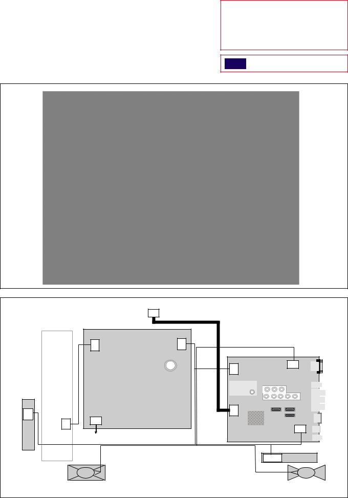
5-2. WIRE DRESSING AND CONNECTOR DIAGRAM 5-2-1. KLV-26 NX400(S/B), NX400(S/B)/S
KLV-26,32 NX400(S/B), 26,32 NX400(S/B)/S, 32,40 NX500
RM-GA018
CAUTION :
1.Do not overpull the wires during dressing --> avoid disconnection of wires.
2.Make sure wires are kept away from sharp edges, heatsinks & other high-temperature parts.
Tape
CN1/
CN100
(3)
Unit
Switch
INVERTER
CNxxxx (14)
|
|
TCON |
|
|
|
|
|
(30) |
|
|
|
CN6202 |
(14) |
CN6201 |
(15) |
|
|
|
|
|
|
BAA |
(4) |
|
|
|
CN6200 |
|
CN4000 |
|
|
Power Unit |
(10) |
|
|
|
|
|
|
|
|
|
|
|
CN9701 |
(30) |
|
CN6000 |
|
|
|
|
|
|
(2) |
|
|
|
|
|
|
|
|
|
CN5600 |
|
|
|
|
|
(30) |
AC Power |
|
|
|
|
|
|
|
|
|
CN100/CN001 |
HLR |
|
|
|
|
(10/12) |
|
|
|
Speaker R |
Speaker L |
– 13 –
KLV-26,32 NX400(S/B), 26,32 NX400(S/B)/S, 32,40 NX500
RM-GA018
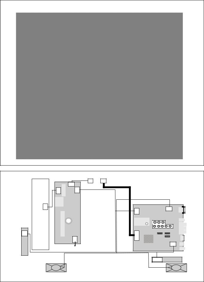
5-2-2. KLV-32 NX400(S/B), NX400(S/B)/S, NX500
WXGA |
FHD |
(KLV-32 NX400(S/B), NX400(S/B)/S) |
(KLV-32NX500) |
|
|
|
|
TCON |
TCON |
|
|
|
|
CN6403 |
|
(4) |
(30/51) |
|
|
|
|
|
|
|
|
|
|
|
|
(6) |
|
|
|
|
|
|
CN6402 |
(14) |
CN6401 |
(15) |
|
|
|
INVERTER |
CNxxxx (14) |
G2LE |
|
|
CN6200 |
BAA |
CN4000 |
|
|
(4) |
|||||
|
|
|
(10) |
|
|||
CN1/ |
|
|
|
|
CN9700/9701 |
|
|
CN100 |
|
|
|
|
(51/30) |
|
|
(3) |
|
|
|
|
|
||
|
|
CN6101 |
(3) |
|
|
||
Switch Unit |
|
|
|
|
|
|
CN5600 |
|
|
|
|
|
|
(30) |
|
|
AC Power |
|
|
|
|||
|
|
|
|
|
|
|
|
|
|
|
|
|
|
CN100/CN001 |
HLR |
|
|
|
|
|
|
(10/12) |
|
|
Speaker R |
|
|
|
|
Speaker L |
|
|
|
|
|
|
– 14 – |
|
|
KLV-26,32 NX400(S/B), 26,32 NX400(S/B)/S, 32,40 NX500
RM-GA018
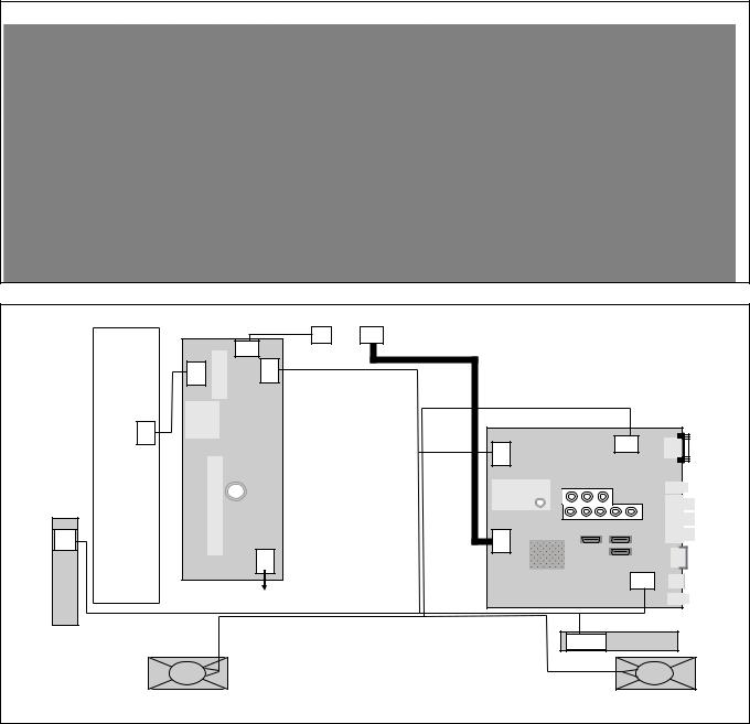
5-2-3. KLV-40NX500
(Except KLV-40NX500(South Africa) |
(KLV-40NX500(South Africa) |
|
|
|
|
|
TCON |
TCON |
|
|
|
|
|
CN6403 |
|
(4) |
(51) |
|
|
|
|
|
|
|
|
|
|
|
|
|
|
(6) |
|
|
|
|
|
|
CN6402 |
(14) |
CN6401 |
(15) |
|
|
|
|
INVERTER |
CNxxxx (14) |
|
G2HE |
|
|
CN6200 |
BAA |
CN4000 |
|
|
|
(4) |
|||||
|
|
|
|
(10) |
|
|||
CN1/ |
|
|
|
|
|
CN9700 |
(51) |
|
CN100 |
|
|
|
|
|
|
||
(3) |
|
|
|
|
|
|
||
|
|
|
CN6101 |
|
|
|
||
|
|
|
(3) |
|
|
|
||
|
|
|
|
|
|
|
|
CN5600 |
Switch Unit |
|
|
|
|
|
|
|
(30) |
|
|
AC Power |
|
|
|
|||
|
|
|
|
|
|
|
|
|
|
|
|
|
|
|
|
CN100/CN001 |
HLR |
|
|
|
|
|
|
|
(10/12) |
|
Speaker R/ Speaker box R |
|
Speaker L/ Speaker box L |
||||||
– 15 –
Loading...