


KP-53HS10
Sony KP-53HS10, KP-61HS10, KV-32XBR400, KV-36XBR400, KV-20FS12 Service Bulletin
...
Model: KV-27V20, KV-27V25, KV-27V35, KV-27V40,
KV-27V45, KV-27V65, KV-32V25, KV-32V35,
KV-32V40, KV-32V65
No.
500
Subject: Part Number Change for Control Doors Date:
September 8, 2000
Symptom:
(XXXX)
The part numbers for the Control Doors are incorrect in the Service Manual.
Solution:
See the table below for the correct part number for the Control Doors.
Model Description Part Number
KV-27V20 Control Door (Black) 4-052-906-31
KV-27V25 Control Door (Black) 4-052-906-21
KV-27V35 Control Door (Black) 4-052-906-41
KV-32V25 Control Door (Black) 4-052-906-21
KV-32V35 Control Door (Black) 4-052-906-51
KV-27V40 Control Door (Gray) 4-074-282-31
KV-27V45 Control Door (Gray) 4-074-282-21
KV27V65 Control Door (Gray) 4-074-282-11
KV-32V40 Control Door (Gray) 4-074-282-31
KV-32V65 Control Door (Gray) 4-074-282-01
CSV-1
Sony Service Company
National Technical Services
A Division of Sony Electronics Inc.
Park Ridge, New Jersey 07656
CONFIDENTIAL
Service Bulletin
TV Products
Reference: A. Mikami
PRINTED IN USA
Model: KP-53HS10, KP-61HS10
No.
501R1
Subject: "D" & "DS" Board Part Number Differences
Based on Serial Number Ranges
Date:
September 29, 2000
Symptom:
(XXXX)
Depending on the television serial number the “D” Board will have a different part
number.
Solution:
Please refer to the tables below if any of the below boards need replacing
KP-53HS10
Description All Serial Number
Starting With 90
All Serial Number
Starting With 97.
“D” & “DS”
Boards
together
A-1346-873-A A-1346-993-A
“D” Board
(Only)
A-1343-771-A A-1343-959-A
“DS” Board
(only)
A-1343-712-A A-1343-712-A
KP-61HS10
Description All Serial Number Starting With 90
“D” & “DS” Boards together A-1346-899-A
“D” Board (only) A-1343-772-A
“DS” Board (only) A-1343-712-A
Note:
There are no P/N changes between Serial Number ranges on the KP-61HS10
CSV-1
Sony Service Company
National Technical Services
A Division of Sony Electronics Inc.
Park Ridge, New Jersey 07656
CONFIDENTIAL
Service Bulletin
TV Products
Reference: PJA Eng.
PRINTED IN USA
Model: KV-32XBR400, KV-36XBR400
No.
503
Subject: White Saturation, Loss Of Detail In Bright
Areas Of Scenes That Are Predominately Dark.
Date:
September 19, 2000
Symptom:
(D325)
In bright areas of scenes that are predominately dark, the picture may be excessively
white and/or bright. This may result in a loss of picture detail in the bright areas.
Conditions under which the symptom may appear:
1- In the full screen mode, when playing a 480
p
source (like progressive-scan DVD).
2- In Twin-View mode, when playing a 480
i
source on the right-side window while TV,
VIDEO-1, VIDEO-2, VIDEO-3, or VIDEO-4 is selected for the left-side window.
Solution:
If the customer complains of this symptom, replace the B-board. B-boards received
from WRPC-AS for service have already had the resistor changes shown below. In
the event that B-boards are out of stock in WRPC-AS, the set's original board can be
updated by making the resistor changes shown below.
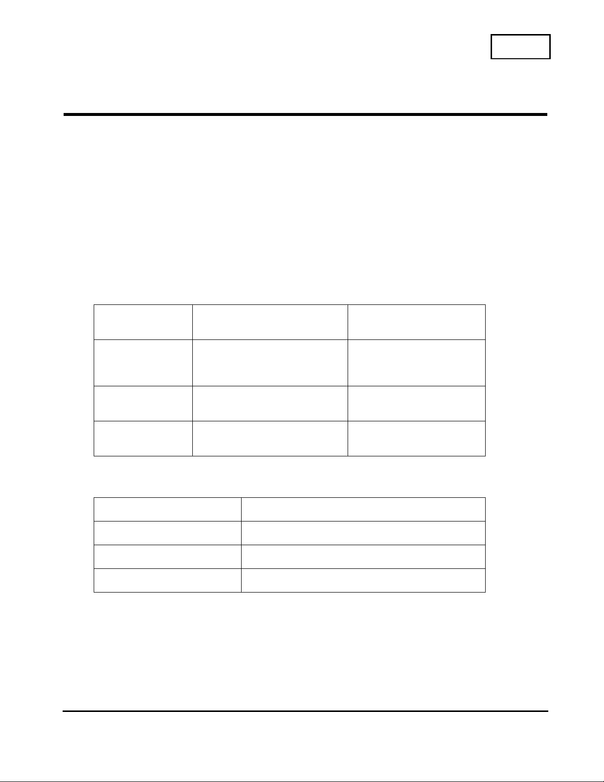
REF FORMER NEW
DESCRIPTION PART NUMBER DESCRIPTION PART NUMBER
13 B COMPLETE
PC BOARD
A-1136-110-A B COMPLETE
PC BOARD
(UPDATED FOR
SERVICE)
A-1136-110-A
(SAME AS
ORGINAL PART
NUMBER)
*R3869
*R3870
*R3871
RESISTOR,
1.2K, 1/16W,
CHIP
1-218-694-11 RESISTOR,
13K, 1/16W,
CHIP
1-218-719-11
*R3477
*R3483
*R3493
RESISTOR, 220
OHM, 1/16W,
CHIP
1-218-676-11 RESISTOR,
2.4K, 1/16W,
CHIP
1-218-701-11
*These parts are only required if the B-board is out of stock in WRPC-AS and you
need to update the set's original B-board.
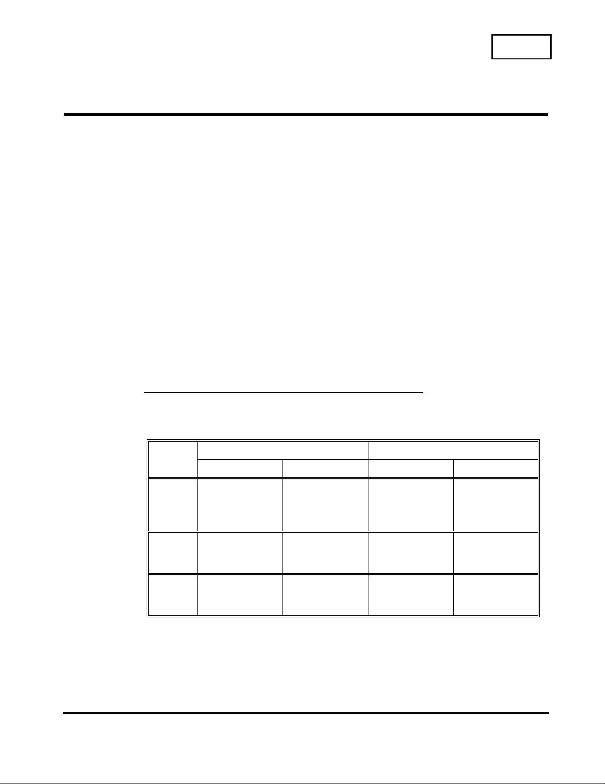
See the next page for the part mounting locations.
CSV-1
Sony Service Company
National Technical Services
A Division of Sony Electronics Inc.
Park Ridge, New Jersey 07656
CONFIDENTIAL
Service Bulletin
TV Products
Reference: ECN KVC04309
PRINTED IN USA
TV Products Service Bulletin No. 503
KV-32XBR400/36XBR400
B-board, side B.
R3871
R3493
R3483
R3870
R3477
R3869
Model: KP-53HS10, KP-61HS10
No.
504
Subject: Audio Dropout/Distortion Under Low AC
Conditions.
Date:
September 21, 2000
Symptom:
(2511)
Audio mutes or distorts under low AC conditions
Solution:
If the customer should complain of audio dropout please make the following circuit
changes on the “K” Board.
1. Change the value of capacitor C2054 to 10uf/ 50v.
Note: It is possible to use a 16v, or 25v rated capacitor as a substitute.
2. Mount a 10uf/50-volt capacitor from the anode side of diode D2023 with the
negative side of the cap to ground.
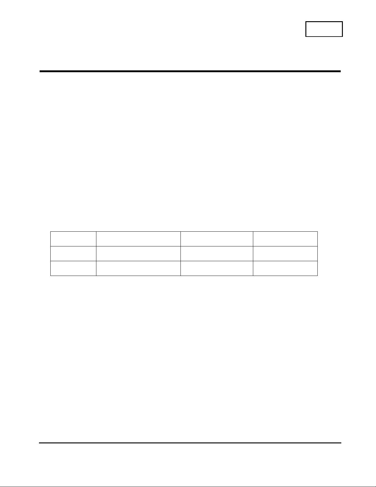
Ref Description Former Description New Part Number
C2054 470UF/16v 10UF/50V 1-126-964-11
C1 Not Mounted 10UF/50V 1-126-964-11
CSV-1
Sony Service Company
National Technical Services
A Division of Sony Electronics Inc.
Park Ridge, New Jersey 07656
CONFIDENTIAL
Service Bulletin
TV Products
Reference: SBR9918
PRINTED IN USA
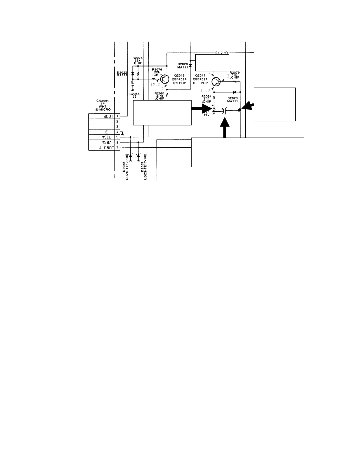
TV Products Service Bulletin No. 504
M
ount a 10uf/50V capacitor with
t
he positive side of the cap to the
a
node side of D2023.
Change C2054
to 10UF
K Board
Q
2017
Positive
side of the
cap
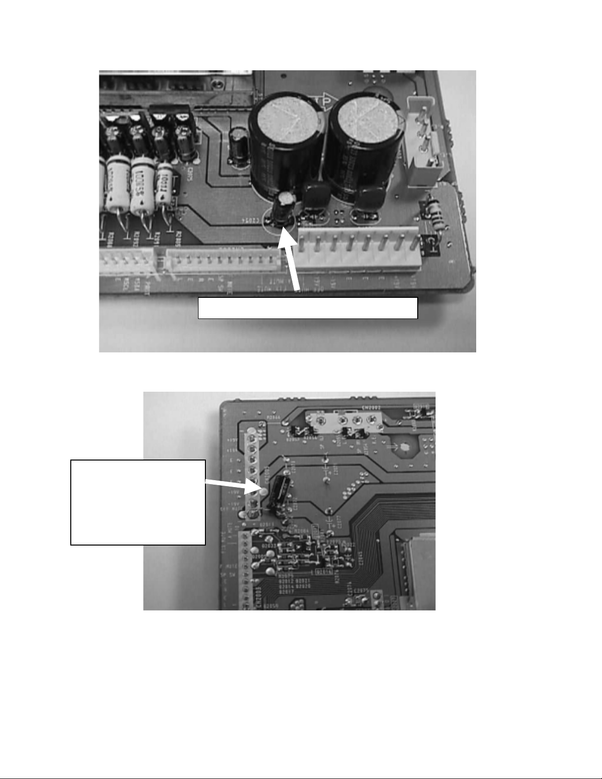
TV Products Service Bulletin No. 504
C2054 Replace with 10uf/50V
Add C1
10uf/50V (positive side
of capacitor to anode
side of D2023).
Model: KV-20FS12
No.
505
Subject: Beznet and Control Door Part Change Date:
October 16, 2000
Symptom:
(xxxx)
Door is hard to open.
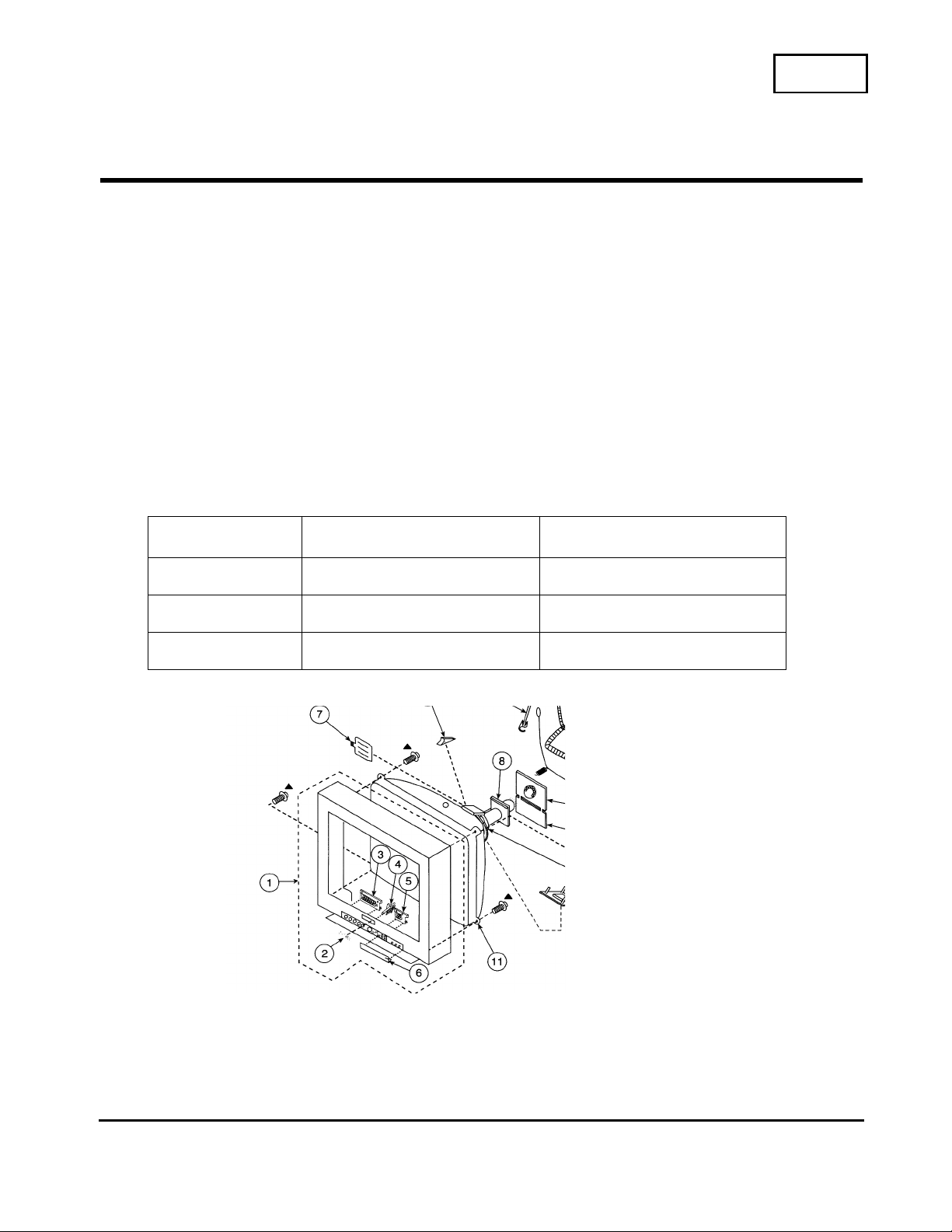
Solution:
The beznet and control door were changed in order to add a retaniner to improve the
operation of the (Ref. 6) control door.
The new Retainer Door and Beznet are not interchangeable with
the older door and Beznet.
Ref Description Part Number
1 Beznet Ass’y X-4037-392-6
6 Retainer Door 4-078-807-01
Not shown Retainer 3-703-574-01
CSV-1
Sony Service Company
National Technical Services
A Division of Sony Electronics Inc.
Park Ridge, New Jersey 07656
CONFIDENTIAL
Service Bulletin
TV Products
Reference: ECN-C04049
PRINTED IN USA
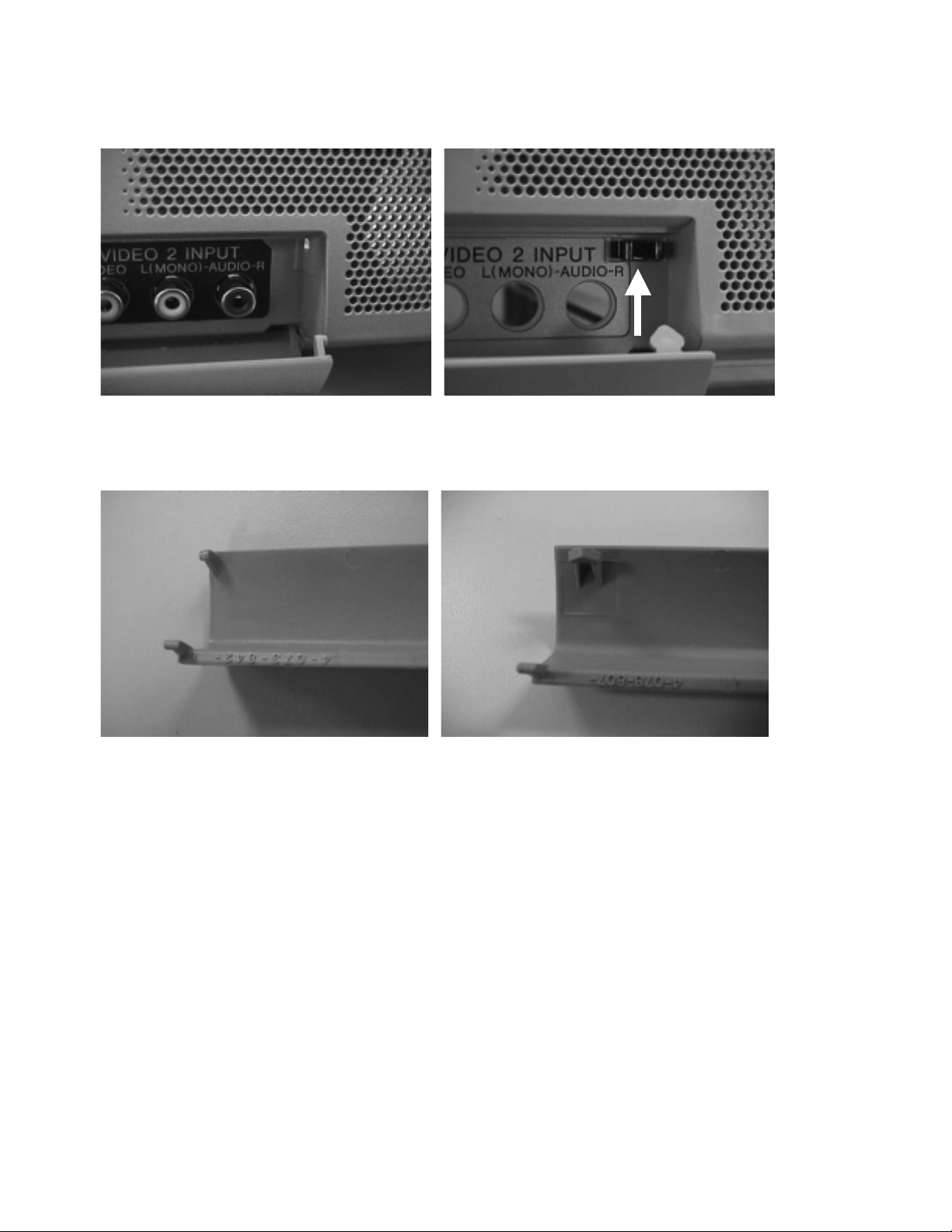
TV Products Service Bulletin No. 505
Original Bezel with no retainer New Bezel with retainer
Original Door New Door with hooks for retainer catching
Model: SU-27FD3, SU-32FD3, SU-36FD3
No.
506
Subject: Repair of TV Stand Date:
October 16, 2000
Symptom:
(116X)
Gray plastic decorative part (ornamental cover) falls off during TV Stand assembly or
when placing/removing TV set from stand.
The ornamental front cover should not be installed, until the set is placed properly on top of
the stand. If the cover is installed before installing the TV, the cover can be pushed forward
causing the staple, which attaches the rail that the cover slides onto, to become loose.
Note:
The Assembly Instruction Manual explicitly states that t h e TV should be properly
positioned on the stand before placement of ornament al covers. Affixing the ornamental cover prior
to installation of TV provides potential for high impact to part attached by staple resulting in the
removal of the decorative part.
SOLUTION:
Reattach existing plastic parts with 1" Panel Board Nails provided by manufacturer's
Service Center. Manufacturer: Tocabi America Corporation.
Sony Operator should recommend that customer complete TV Stand Warr ant y Card
with short description of pr oblem (ex: staples removed, et c. ). Fax card, along with
copy of sales receipt,
to (619) 656-8181. After this operation, customer will r eceive " FD3 fix-it kit" within 5
days.
If customer feels need to follow-up with their request, please provide Tocabi Service Center
phone number (619) 661-6136 ext. 204.
"FD3 fix-it-kit'' contents:
(5) 1" Panel Board Nails.
(1) Metal Dowel for ease of installation.
(1) Service Instruction
SU-27FD3 SU-32FD3 SU-36FD3
KV-27FV15 KV-32FV15 KV-36FV15
KV-27FV16 KV-32FV16 KV-36FV16
KV-27FS12 KV-32FV26 KV-36FV26
KV-27FS16 KV-32FS12 KV36FS12
KV-32FS16 KV-36FS16
CSV-1
Sony Service Company
National Technical Services
A Division of Sony Electronics Inc.
Park Ridge, New Jersey 07656
CONFIDENTIAL
Service Bulletin
TV Products
Reference: SBTV2000-11
PRINTED IN USA
Model: KV-32XBR400, KV-36XBR400
No. 507R1
Subject: TV Turns Itself Off. Date: August 8, 2001
Symptom:
(3111) The TV turns itself off after the customer has been watching it for a while. It may turn
off within minutes of turning it on, or it may take an hour or more before it turns itself
off. The set can usually be turned back on again by cycling the TV's front panel
power switch.
Solution: This symptom may be caused by a drift of the hold-down adjustment that was set at
the factory. As this adjustment in the field requires the replacement of 3
potentiometers on the D-board and the availability of a precision high-voltage meter
(0.2 Kv resolution), the recommended solution is to replace the D-board.
MODEL DESCRIPTION PART NUMBER
KV-32XBR400 D-BOARD A-1346-947-A
KV-36XBR400 D-BOARD A-1346-948-A
KV-32XBR400
KV-36XBR400
HIGH VOLTAGE LEAD 1-251-715-22
KV-32XBR400
KV-36XBR400
FOCUS LEAD 1-900-805-19
NOTE 1: After replacing the D-board the original board must be sent back to Sony
where it will be re-adjusted and returned to float stock. Countermeasures will be
applied to these boards to prevent the hold-down adjustment from drifting.
Instructions and paperwork for returning the boards to Sony are included with new
D-boards supplied by WRPC-AS. In the event the return shipping materials are not
available, please be sure to return the boards to the following address:
Sony Technology Center
Attention S.A.Y.S. Dept.
Dock #22
1001 Technology Drive
Mt. Pleasant, Pa. 15666
Be sure to include the following information:
NARDA claim number, invoice number, model number, serial number, customer
name and phone number, your name, your company name, your Sony servicer
account number and parts account number, and the date the repair was performed.
This information is required to ensure that your parts account will be credited for the
core charge when the original board is returned.
IMPORTANT! See note 2 on next page.
CSV-1
Sony Service Company
National Technical Services
A Division of Sony Electronics Inc.
Park Ridge, New Jersey 07656
CONFIDENTIAL
Service Bulletin
TV Products
S
Reference: PRINTED IN USA
TV Products Service Bulletin No. 507R1
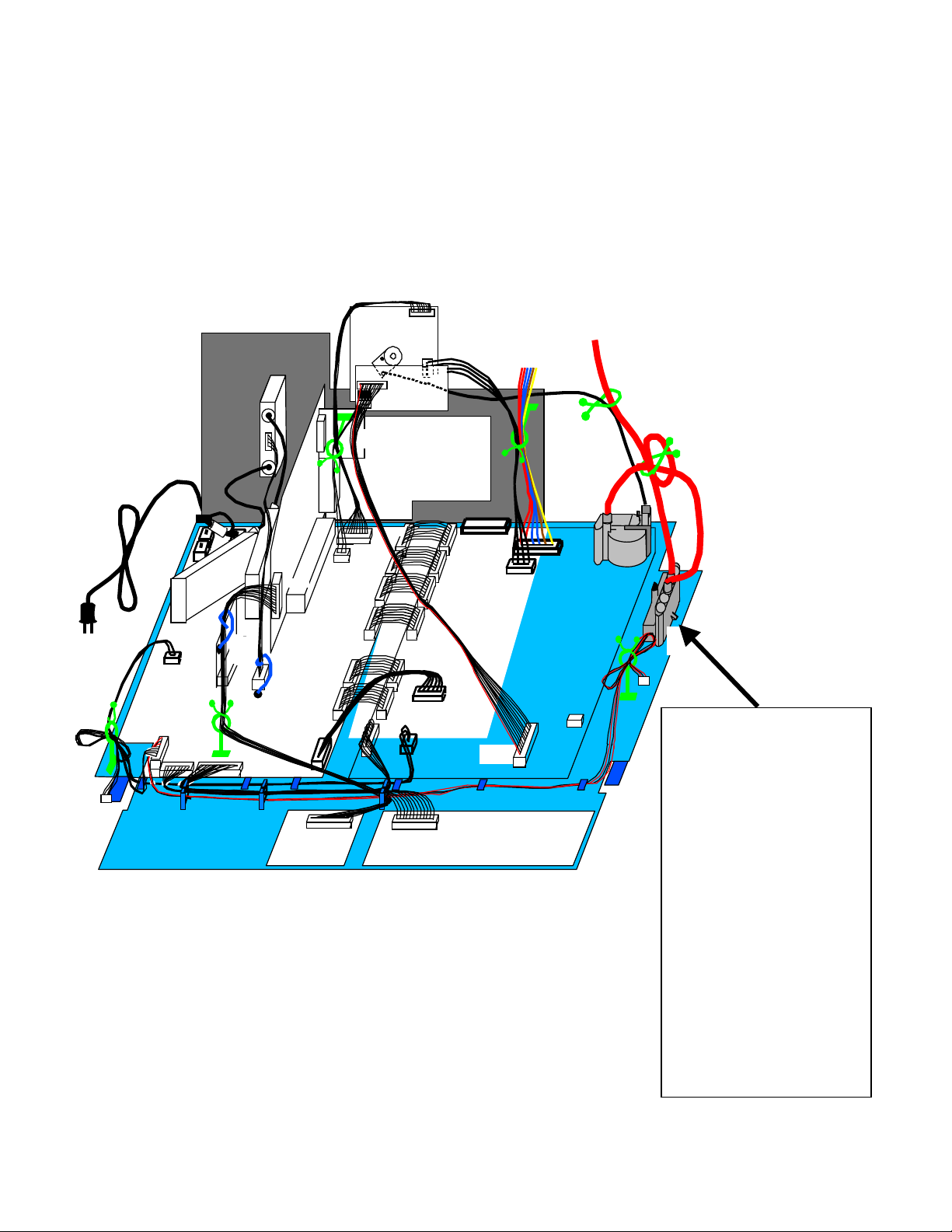
NOTE 2: Early production units used a high-voltage block between the flyback
transformer and the CRT. In this case, the high-voltage block must be bypassed, and
the original high-voltage leads must be removed from the high-voltage block and
discarded. New boards received from WRPC-AS require a high-voltage lead that
connects directly to the CRT from the flyback transformer. Some D-boards
received from WRPC-AS will include the proper HV and focus leads, while other
boards received will not include any leads. Therefore, if you do not have a
spare HV lead (part number 1-251-715-22) and a new focus lead (part number
1-900-805-19) you must order these leads when you order the D-board.
D
DD
D
[ ]
[ ][ ]
[ ]
A
AA
A
[ ]
[ ][ ]
[ ]
HA
HAHA
HA
[
[[
[
]
]]
]
HB
HBHB
HB
[
[[
[]
]]
]
BUS CONN
[B]
[B][B]
[B]
U
UU
U
[ ]
[ ][ ]
[ ]
[
[[
[
S
SS
S
[
[[
[
]
]]
]
W
W
W
W
]
]]
]
C
CC
C
[ ]
[ ][ ]
[ ]
ANT
ANTANT
ANT
SW
SWSW
SW
MAIN
MAINMAIN
MAIN
SUB
SUBSUB
SUB
DX-1A
CHASSIS
ASSEMBLY
[BC]
[BC][BC]
[BC]
Some sets have a
high-voltage
block. This block
must be bypassed
when replacing the
D-board. The new
high-voltage lead
must be connected
directly between
the new D-board
and the CRT. The
original high-
voltage leads must
be removed and
discarded.
Model: KV-27FS16, KV-27FV16, KV-32FS16
No.
508
Subject: PIP White Balance is Green or Pinkish Date:
October 19, 2000
Symptom:
(1375)
The white balance of PIP may appear pink in the RF or Video mode. In video 4
(YUV) the white balance may be green.
Solution:
If the customer should complain of this symptom the following adjustments will be
needed.
Model S erial number range where adjustment may be needed
KV-27FS16 8019034 through 8029604
KV-27FV16 8006336 through 8033309
KV-32FS16 8006997 through 8013880
[PIP W/B Adjustment]
1. Set PIP ON and display the RF no signal (Snow Noise) in PIP picture
2. Set Main Picture to Video4 (Y, Pb, Pr input) with out si gn al (Blac k Picture)
3. In the Service Mode alternately select the “PVP1” and “PUP1” and adjust the white balance
with the remotes 3 or 6 button.
4. Set Main Picture to Video1 without signal (Black Picture)
5. In the Service Mode alternately select the “PVP3” and “PUP3” and adjust the white balance
with the remotes 3 or 6 button.
6. Tune to any TV channel that’s in color for Main Picture
7. In the Service Mode alternately select the “PVP2” and “PUP2” and adjust the white balance
with the remotes 3 or 6 button.
CSV-1
Sony Service Company
National Technical Services
A Division of Sony Electronics Inc.
Park Ridge, New Jersey 07656
CONFIDENTIAL
Service Bulletin
TV Products
Reference: TV2000-14
PRINTED IN USA
Model: FDL-250T
No.
509
Subject: UHF Red Bar Display Bent Date:
November 27, 2000
Symptom:
(113X)
UHF red channel bar becomes bent as volume is increased.
Solution:
If the customer should complain of the symptom above please perform the following.
Serial number range aff ective 4000001 through 4004700
Ref Schematic
Location
Description
Former
Description
New
P/N
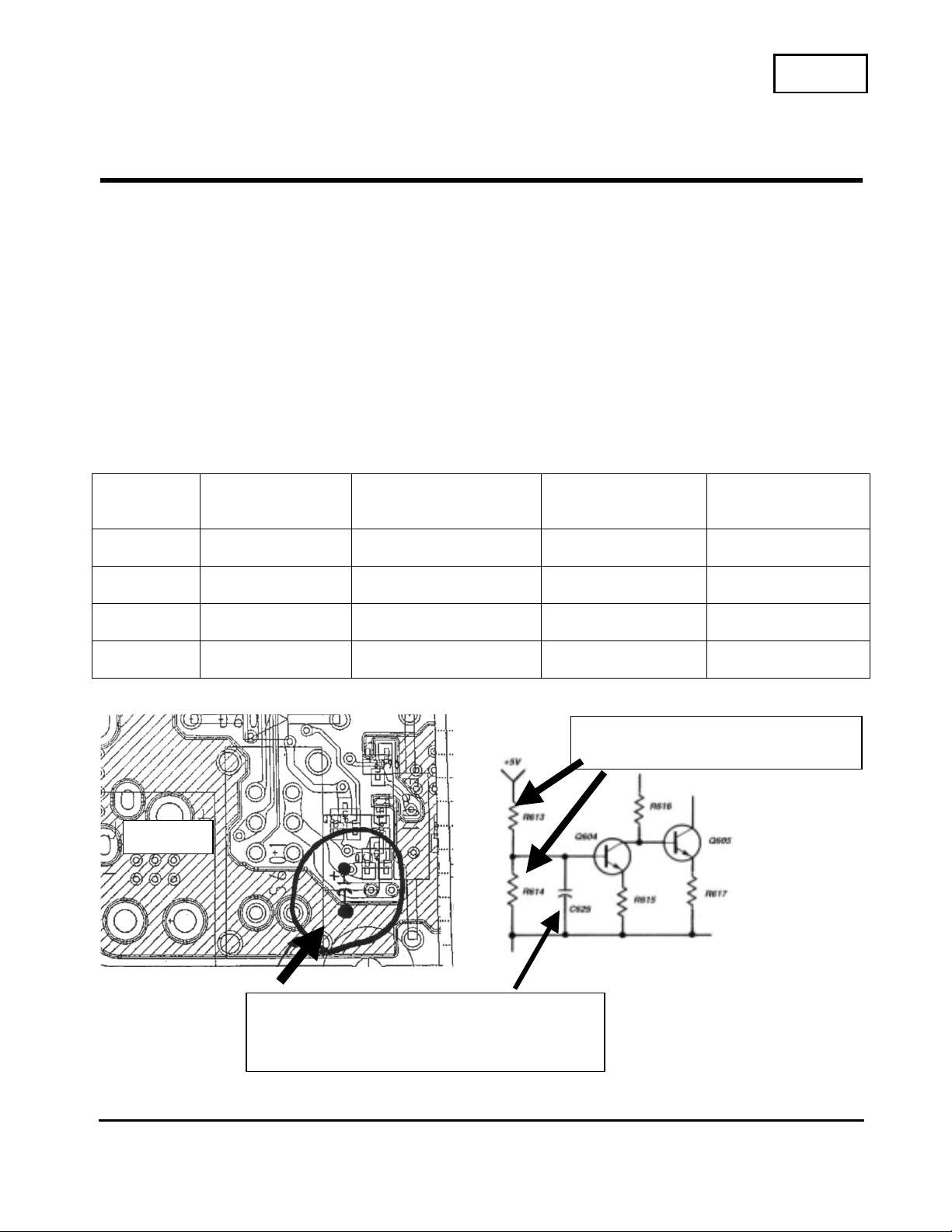
C625 I-5 Not used originally 10uf/6,3v 1-104-851-11
R010 F-7 27 Ohm 10 Ohm 1-216-001-00
R613 I-5 10K 1/16W 22K 1/16W 1-216-837-11
R614 I-5 10K 1/16W 22K 1/16 W 1-216-837-11
CSV-1
Sony Service Company
National Technical Services
A Division of Sony Electronics Inc.
Park Ridge, New Jersey 07656
CONFIDENTIAL
Service Bulletin
TV Products
Reference: Masaaki, Koike
PRINTED IN USA
Add 10uf cap between Q604 base (+)
and ground (-)
C
hange R613 & R614 to22K
1
/16W
J601
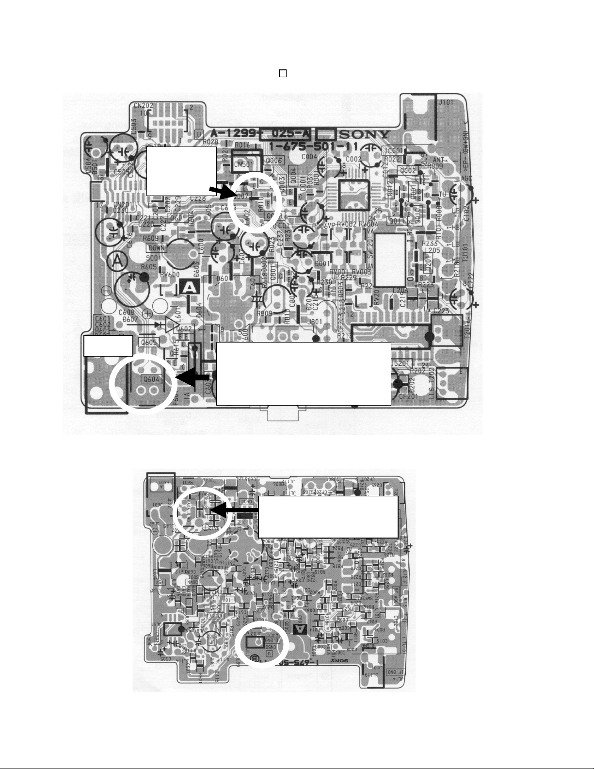
TV Products Service Bulletin No. 509
R010
Change to
10 ohm
Add to the base of Q604 a
10uf/6.3v capacitor.
Positive end of capacitor to
base of Q604
R
613 & R614 Change
t
o 22K 1/16 Watt
J601
Model: KP-53HS10, KP-61HS10
No.
510
Subject: Circuit change for white saturation Date:
November 27, 2000
Symptom:
(1322)
Saturation/low resolution is seen on the screen with high level white signal.
Saturation starts around 1.2vp-p of signal level on all Y, Pb, Pr inputs.
Solution:
If the customer should complain of the symptom above the following resistor values
must be changed, on the conductor side of the “A” Board.
Ref A Board Location Former New Part Number
R1462 D-9 0 Ohm 390 Ohm
Chip res.
1-216-641-11
R1467 F-8 0 Ohm 390 Ohm
Chip res.
1-216-641-11
R1471 F-8 0 Ohm 390 Ohm
Chip res.
1-216-641-11
Continue next page
CSV-1
Sony Service Company
National Technical Services
A Division of Sony Electronics Inc.
Park Ridge, New Jersey 07656
CONFIDENTIAL
Service Bulletin
TV Products
Reference: SBR9917
PRINTED IN USA
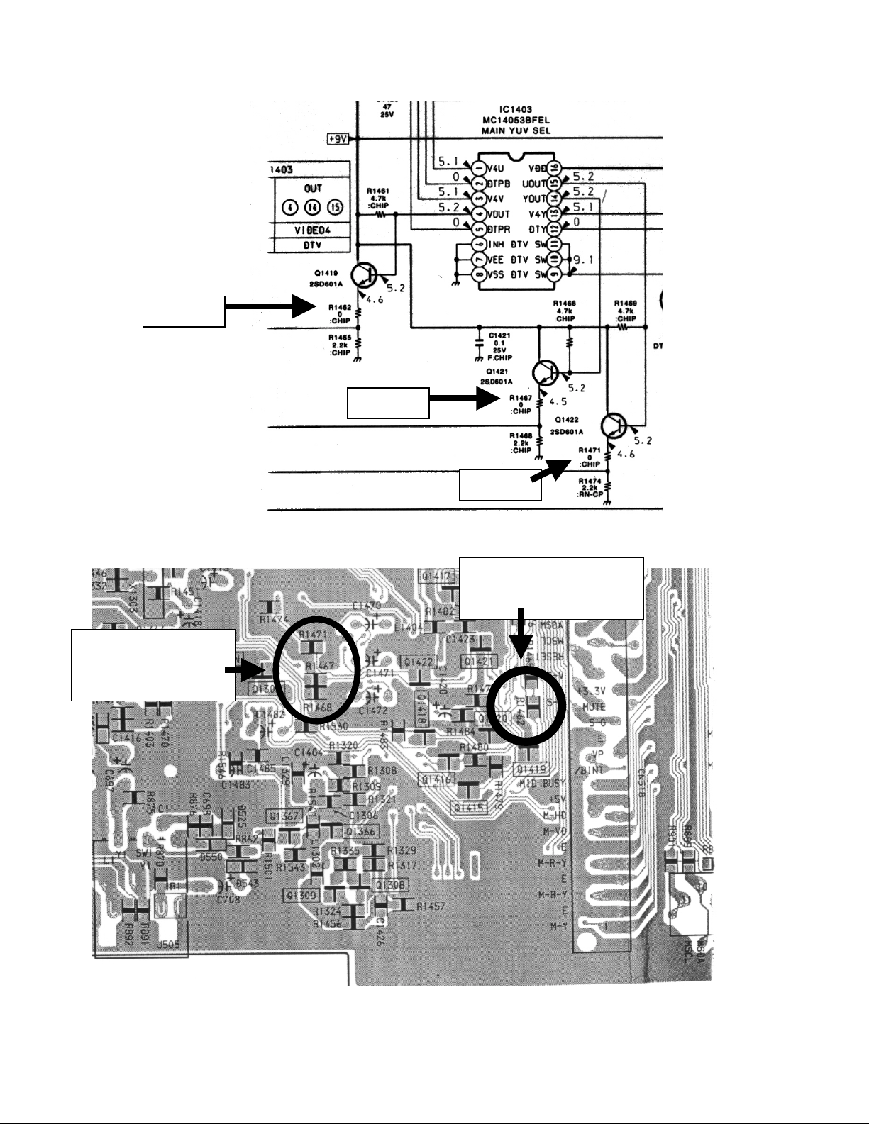
TV Products Service Bulletin No. 510
`
R1467 & R1471
Change to 390
Ohm Chip Res.
R
1462 Change to
3
90 Ohm Chip Res.
R1462
R1467
R
1471
A Boa rd
Model: KP-53HS10, KP-53XBR300
KP-61HS10, KP-61XBR300
No.
511
Subject: Picture distortion occurs when connected to
Star Choice (HDD-201) satellite receiver.
Date:
December 6, 2000
Symptom:
(132X)
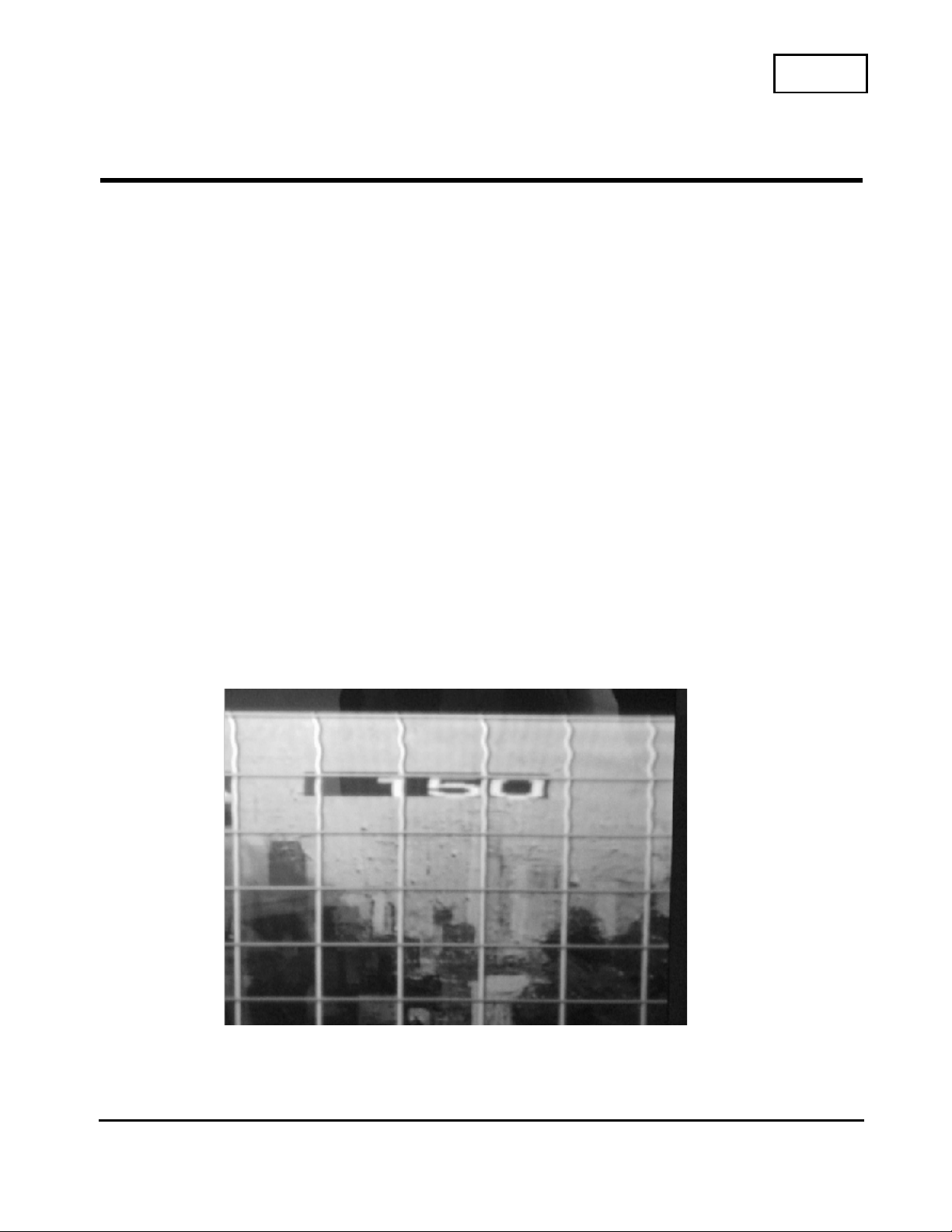
Topside of the picture is distorted in 1080i/480p when connected to Star Choice
satellite receiver into the projection TV’s Video 5 input. This symptom will only occur
in a component Y, Pb, Pr configuration.
Cause:
The HDD201 has non-standard sync pulses on the Y output signal during the vertical
blanking time. These pulses effect the TV’s video processing resulting in picture
distortions.
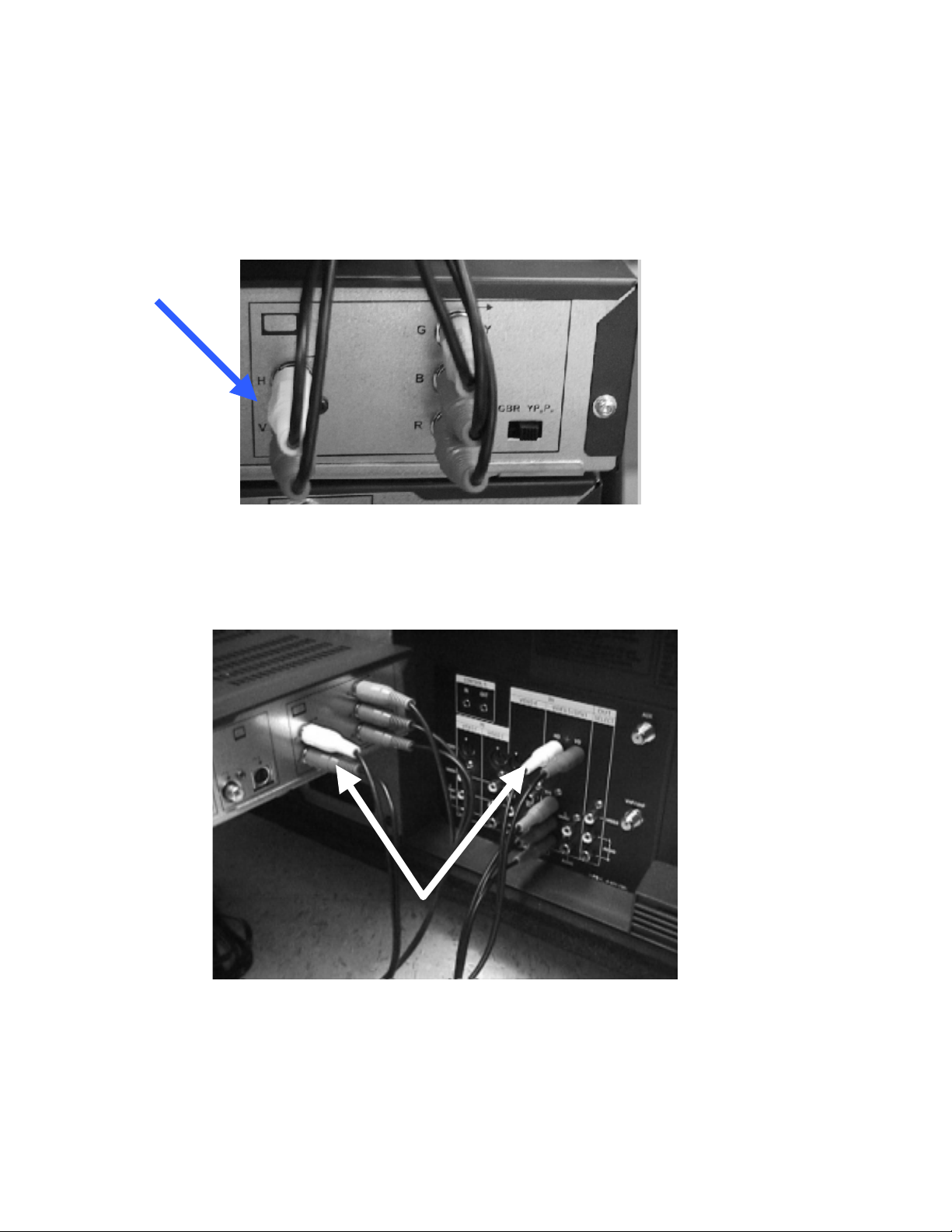
Solution:
For both Y, Pb, Pr and RGB connection configurations, a separate H & V Sync
connection cable must be used between the satellite receiver and the video 5 input on
the TV. In order to correct this symptom, a standard type RCA audio patch cable may
be used. (See photos below.)
NOTE:
The Star Choice (HDD-201) satellite receiver is designed to be sold and used in
Canada only. Therfore this problem should not be seen in the USA.
Picture of symptom on screen:
CSV-1
Sony Service Company
National Technical Services
A Division of Sony Electronics Inc.
Park Ridge, New Jersey 07656
CONFIDENTIAL
Service Bulletin
TV Products
Reference: TV2000-15
PRINTED IN USA
TV Products Service Bulletin No. 511
Connection on rear side of Star Choice HDD-201:
Separate H and V sync cables required to connect to
KP-53HS10 and KP-61HS10 video 5 input.
Connection to Rear side of HS10 model
Connect separate H and V sync from Star Choice cables to
KP-53 and 61HS10 video 5 input
Model: KP-57XBR10W, KP-65XBR10W
No.
512
Subject: Intermittent retrace lines in picture Date:
December 6, 2000
Symptom:
(5344)
Retrace lines may appear when the set is first turned on from a cold start for about
one second.
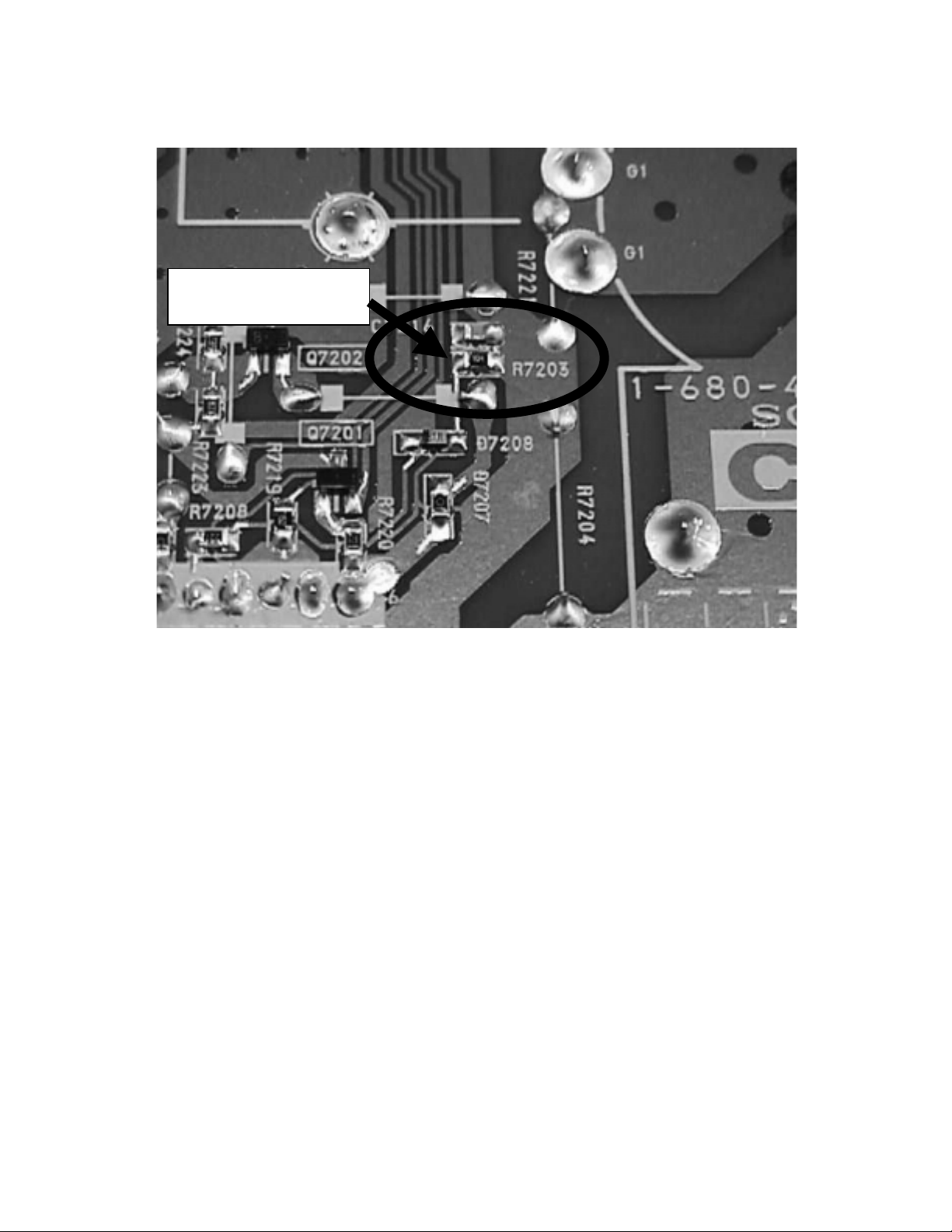
Solution:
If the customer should complain of this symptom please perform the following circuit
change on the CG Board.
Replace the resistor in the table below with the new resis tor val ue on the
CG Board.
Change GCUT to 10 in the Service mode.
Readjust the following items: G-2 adjustment, White balance, and Sub-bright all in the
“Standard” picture mode.
Ref. Description Part Number
R7203 Chip res. 100K
1/10 Watt
1-216-097-00
Model Serial Number Range that
does not have this value
change.
KP-57XBR10W 9000001-90000700
KP-65XBR10W 9000001-90000200
Note: CG boards in WRPC will be corrected to the new value resistor.
CSV-1
Sony Service Company
National Technical Services
A Division of Sony Electronics Inc.
Park Ridge, New Jersey 07656
CONFIDENTIAL
Service Bulletin
TV Products
Reference: PP0011021
PRINTED IN USA
TV Products Service Bulletin No. 512
CG Board
Replace R7203 with
a 100K 1/10 W
Model: KP-41T15, KP-41T25, KP-41T35, KP-46C36
KP-46S15, KP-46S17, KP-46S25, KP-46V25
KP-46V35, KP-48S35, KP-48V45, KP-53S15
KP-53S17, KP-53S25, KP-53S35, KP-53V25
KP-53V35, KP-53V45, KP-53XBR45
KP-53XBR4CT, KP-61S35, KP-61V25
KP-61V35, KP-61V45, KP-61XBR48
No. 513R1
Subject: CRT Replacement Date: August 21, 2001
Symptom:
(161X) Ground of replacement CRT may be different than the original. Heater resistor value
change may be required.
Solution: When replacing the CRT the following changes may be necessary.
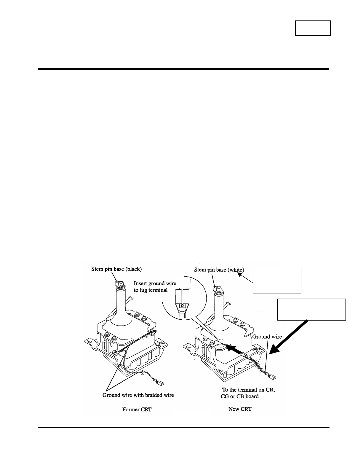
1. When replacing the CRT the original may have used a braided wire across the CRT to ground the
CRT and CRT Board. The replacement CRT uses a grounding wire that connects to a ground lug.
This grounding lug wire should be packed in the replacement CRT box. See picture below.
CSV-1
Sony Service Company
National Technical Services
A Division of Sony Electronics Inc.
Park Ridge, New Jersey 07656
CONFIDENTIAL
Service Bulletin
TV Products
S
Reference: CRT Group PJA PRINTED IN USA
Ground wire P/N
1-900-235-84
Fig 1
See note on
last page
TV Products Service Bulletin No. 513R1
2.
Heater resistor value change.
When the CRT is replaced it is required to check the heater resistor value. This resistor value will
change depending on how many newer CRTs are used. It should be checked even if you are only
changing one CRT because one might have been replaced prior to your present repair. Failure to do so
may cause the CRT life span to be shortened.
In order to determine if the CRT heater resistor is the older value or not, check the color of the CRT
plastic pin base stem. (See Fig 1)
Black stem indicates an older CRT and the value of the heater resistor was not changed.
White stem indicates a newer CRT and the value of the heater resistor may require a different value.
3. Procedure for replacing the heater resistor.
1. After replacing the defective CRT, check the color of the CRT plastic pin base stem of all three
CRTs. (See Fig 1)
2. The value of the heater resistor, on the E or G Board depending on the model, will be
determined by how many of the CRTs have a white stem base. Refer to the chart below.
3. Check the heater resistor value in the set and confirm if it is the correct value as per the chart
below. If not please replace the resistor with the correct value.
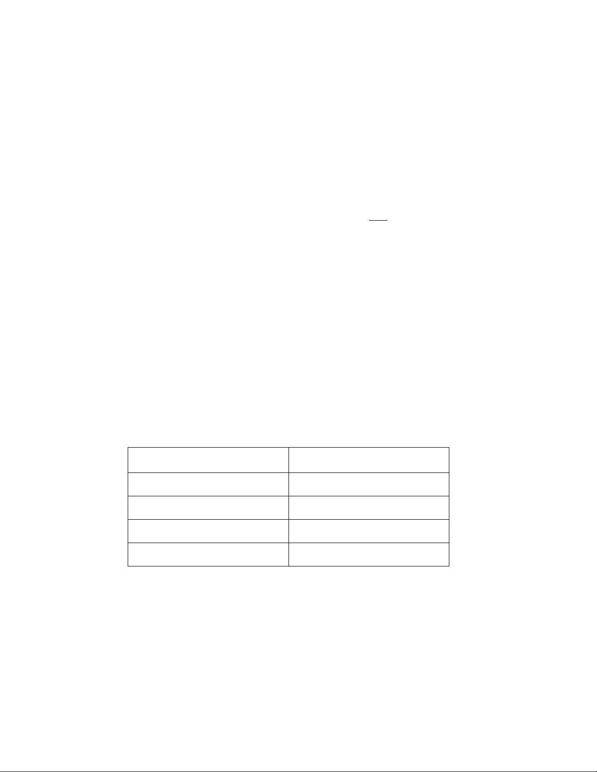
Replace resistors for the heater circuit with the correct value resistors
specified by the number of the new heater CRTs as shown in the following chart.
Part Number Chart
Description Part Number
0.22 Ohm 1 Watt 1-216-341-11
0.47 Ohm 1 Watt 1-216-345-11
1.2 Ohm 3 Watt 1-216-390-11
1.5 Ohm 3 W 1-216-391-11
See the tables below to determine what value resistor change is required
if necessary.
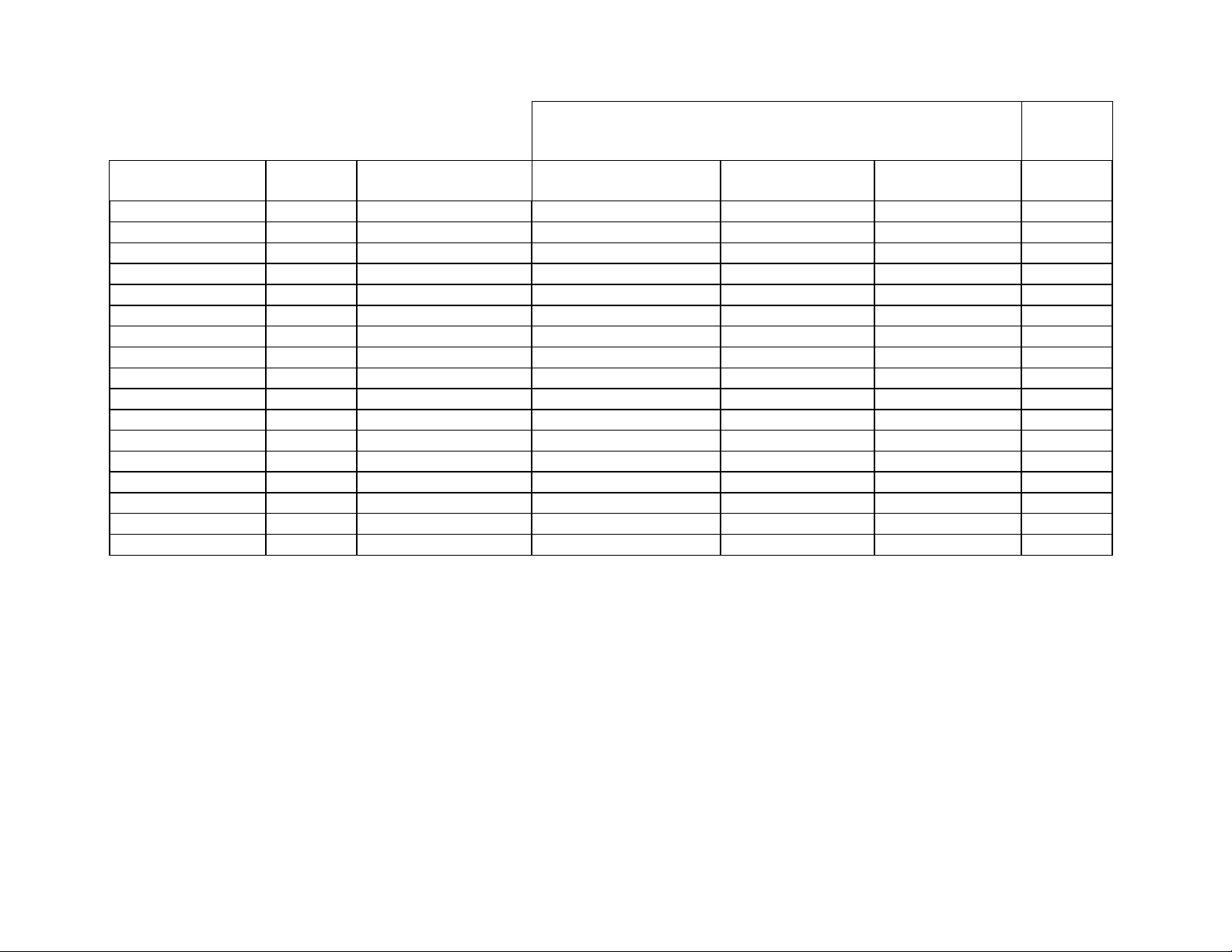
New Heater Resistor
Quantity of new type CRTs (white stem base) in the set
after defective CRTs are replaced
Model Chassis Former Heater
Resistor
One Two Three Board
KP-41T15 RA-1 1 Ohm 1/12 W (R835) No need to replace 0.47 Ohm 1W 0.22 Ohm 1W E Board
KP-41T25 RA-1 1 Ohm 1/12 W (R835) No need to replace 0.47 Ohm 1W 0.22 Ohm 1W E Board
KP-46S15 RA-1 1 Ohm 1/12 W (R835) No need to replace 0.47 Ohm 1W 0.22 Ohm 1W E Board
KP-46S17 RA-1 1 Ohm 1/12 W (R835) No need to replace 0.47 Ohm 1W 0.22 Ohm 1W E Board
KP-46S25 RA-1 1 Ohm 1/12 W (R835) No need to replace 0.47 Ohm 1W 0.22 Ohm 1W E Board
KP-46V25 RA-1 1 Ohm 1/12 W (R835) No need to replace 0.47 Ohm 1W 0.22 Ohm 1W E Board
KP-46V35 RA-1 1 Ohm 1/12 W (R835) No need to replace 0.47 Ohm 1W 0.22 Ohm 1W E Board
KP-53S15 RA-1 1 Ohm 1/12 W (R835) No need to replace 0.47 Ohm 1W 0.22 Ohm 1W E Board
KP-53S17 RA-1 1 Ohm 1/12 W (R835) No need to replace 0.47 Ohm 1W 0.22 Ohm 1W E Board
KP-53S25 RA-1 1 Ohm 1/12 W (R835) No need to replace 0.47 Ohm 1W 0.22 Ohm 1W E Board
KP-53V25 RA-1 1 Ohm 1/12 W (R835) No need to replace 0.47 Ohm 1W 0.22 Ohm 1W E Board
KP53V35 RA-1 1 Ohm 1/12 W (R835) No need to replace 0.47 Ohm 1W 0.22 Ohm 1W E Board
KP-53XBR45 RA-1 1 Ohm 1/12 W (R835) No need to replace 0.47 Ohm 1W 0.22 Ohm 1W E Board
KP-53XBR4CT RA-1 1 Ohm 1/12 W (R835) No need to replace 0.47 Ohm 1W 0.22 Ohm 1W E Board
KP-61V25 RA-1 1 Ohm 1/12 W (R835) No need to replace 0.47 Ohm 1W 0.22 Ohm 1W E Board
KP-61V35 RA-1 1 Ohm 1/12 W (R835) No need to replace 0.47 Ohm 1W 0.22 Ohm 1W E Board
KP-61XBR48 RA-1 1 Ohm 1/12 W (R835) No need to replace 0.47 Ohm 1W 0.22 Ohm 1W E Board
Continue on next page
TV Products Service Bulletin No. 513R1
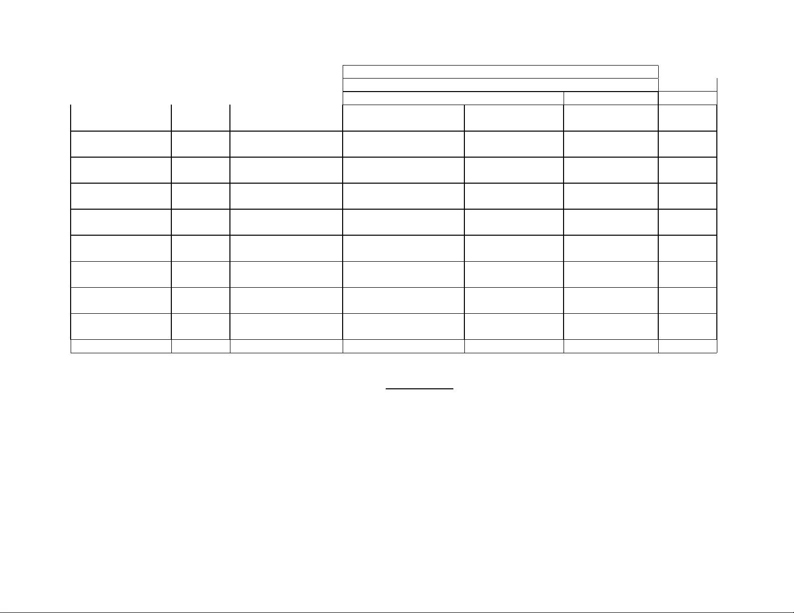
New Heater Resistor
Quantity of new type CRTs (white stem base) in the set
after defective CRTs are replaced
Model Chassis Former Heater
Resistor
One Two Three Board
KP-41T35 RA-2 1.8 Ohm 3 W (R569)
0.68 Ohm 3W (R540)
No need to replace
No need to replace
1.5 Ohm 3 W
No need to replace
1.2 Ohm 3W
0.47 Ohm 3W
G Board
KP-43C36 RA-2 1.8 Ohm 3 W (R569)
0.68 Ohm 3W (R540)
No need to replace
No need to replace
1.5 Ohm 3 W
No need to replace
1.2 Ohm 3W
0.47 Ohm 3W
G Board
KP48S35 RA-2 1.8 Ohm 3 W (R569)
0.68 Ohm 3W (R540)
No need to replace
No need to replace
1.5 Ohm 3 W
No need to replace
1.2 Ohm 3W
0.47 Ohm 3W
G Board
KP-48V45 RA-2 1.8 Ohm 3 W (R569)
0.68 Ohm 3W (R540)
No need to replace
No need to replace
1.5 Ohm 3 W
No need to replace
1.2 Ohm 3W
0.47 Ohm 3W
G Board
KP-53S35 RA-2 1.8 Ohm 3 W (R569)
0.68 Ohm 3W (R540)
No need to replace
No need to replace
1.5 Ohm 3 W
No need to replace
1.2 Ohm 3W
0.47 Ohm 3W
G Board
KP-53V45 RA-2 1.8 Ohm 3 W (R569)
0.68 Ohm 3W (R540)
No need to replace
No need to replace
1.5 Ohm 3 W
No need to replace
1.2 Ohm 3W
0.47 Ohm 3W
G Board
KP-61S35 RA-2 1.8 Ohm 3 W (R569)
0.68 Ohm 3W (R540)
No need to replace
No need to replace
1.5 Ohm 3 W
No need to replace
1.2 Ohm 3W
0.47 Ohm 3W
G Board
KP-61V45 RA-2 1.8 Ohm 3 W (R569)
0.68 Ohm 3W (R540)
No need to replace
No need to replace
1.5 Ohm 3 W
No need to replace
1.2 Ohm 3W
0.47 Ohm 3W
G Board
Note: As of 4/24/01, PJ CRT will begin the use of colored stem caps in their process. The color of the stem cap will match the color of the CRT.
They will begin with red and green. White will continue to be used on the blue tubes until the supply is exhausted, at which time they will begin the
use of blue stem caps also, we expect this to be sometime in June 2001. Please see picture below.
There has been no material change, only a dye added for color. Engineering analysis of dimensions, arc testing, flame testing, and pin cap
adhesion show no change in performance from our current stem cap.
Please note, that depending upon shipments, you may continue to see white stem caps only for some time.
 Loading...