


 Loading...
KLV-32W400A/40W400A/46W400A/52W400A
SERVICE MANUAL
E Model
India Model
Indonesia Model
Middle East Model
Thailand Model
Philippines Model
Saudi Arabia Model
South Africa Model
RM-GA011 KLV-32W400A/40W400A/46W400A/52W400A
EX1 CHASSIS
LCD Colour TV

SPECIFICATIONS |
KLV-32/40/46/52W400A (GA) 2
KLV-32/40/46/52W400A (GA) 3
WARNINGS AND CAUTIONS
CAUTION
These servicing instructions are for use by qualified service personnel only.
To reduce the risk of electric shock, do not perform any servicing other than that contained in the operating instructions unless you are qualified to do so.
WARNING!!
An isolation transformer should be used during any service to avoid possible shock hazard, because of live chassis.
The chassis of this receiver is directly connected to the ac power line.
!SAFETY-RELATED COMPONENT
WARNING!!
Replace all components with Sony parts whose part numbers appear as shown in this manual or in supplements
published by Sony.
SAFETY-RELATED COMPONENT
WARNING
It is essential that all critical parts be replaced only with the part number specified in the electrical parts list to prevent electric shock, fire, or other hazard.
NOTE: Do not modify the original design without obtaining written permission from the manufacturer or you will void the original parts and labor guarantee.
USE CAUTION WHEN HANDLING THE LCD PANEL
When repairing the LCD panel, be sure you are grounded by using a wrist band.
When repairing the LCD panel on the wall, the LCD panel must be secured using the 4 mounting holes on the rear cover.
1)Do not press on the panel or frame edge to avoid the risk of electric shock.
2)Do not scratch or press on the panel with any sharp objects.
3)Do not leave the module in high temperatures or in areas of high humidity for an extended period of time.
4)Do not expose the LCD panel to direct sunlight.
5)Avoid contact with water. It may cause a short circuit within the module.
6)Disconnect the AC power when replacing the backlight (CCFL) or inverter circuit.
(High voltage occurs at the inverter circuit at 650Vrms.)
7)Always clean the LCD panel with a soft cloth material.
8)Use care when handling the wires or connectors of the inverter circuit. Damaging the wires may cause a short.
9)Protect the panel from ESD to avoid damaging the electronic circuit (C-MOS).
KLV-32/40/46/52W400A (GA) 4

SAFETY CHECK-OUT
After correcting the original service problem, perform the following safety checks before releasing the set to the customer:
1.Check the area of your repair for unsoldered or poorly soldered connections. Check the entire board surface for solder splashes and bridges.
2.Check the interboard wiring to ensure that no wires are “pinched” or touching high-wattage resistors.
3.Check that all control knobs, shields, covers, ground straps, and mounting hardware have been replaced. Be absolutely certain that you have replaced all the insulators.
4.Look for unauthorized replacement parts, particularly transistors, that were installed during a previous repair. Point them out to the customer and recommend their replacement.
5.Look for parts which, though functioning, show obvious signs of deterioration. Point them out to the customer and recommend their replacement.
6.Check the line cords for cracks and abrasion. Recommend the replacement of any such line cord to the customer.
7.Check the antenna terminals, metal trim, “metallized” knobs, screws, and all other exposed metal parts for AC leakage. Check leakage as described below.
Leakage Test
The AC leakage from any exposed metal part to earth ground and from all exposed metal parts to any exposed metal part having a return to chassis, must not exceed 0.5 mA (500 microamperes).
Leakage current can be measured by any one of three methods.
1.A commercial leakage tester, such as the Simpson 229 or RCA WT-540A. Follow the manufacturers’ instructions to use these instructions.
2.A battery-operated AC milliampmeter. The Data Precision 245 digital multimeter is suitable for this job.
3.Measuring the voltage drop across a resistor by means of a VOM or battery-operated AC voltmeter. The “limit” indication is 0.75 V, so analog meters must have an accurate low voltage scale.
The Simpson’s 250 and Sanwa SH-63TRD are examples of passive VOMs that are suitable. Nearly all battery-operated digital multimeters that have a 2 VAC range are suitable (see Figure A).
How to Find a Good Earth Ground
A cold-water pipe is a guaranteed earth ground; the cover-plate retaining screw on most AC outlet boxes is also at earth ground. If the retaining screw is to be used as your earth ground, verify that it is at ground by measuring the resistance between it and a cold-water pipe with an ohmmeter. The reading should be zero ohms.
If a cold-water pipe is not accessible, connect a 60to 100-watt troublelight (not a neon lamp) between the hot side of the receptacle and the retaining screw. Try both slots, if necessary, to locate the hot side on the line; the lamp should light at normal brilliance if the screw is at ground potential (see Figure B).
To Exposed Metal
Parts on Set
Trouble Light
Ohmmeter
AC Outlet Box
AC
0.15 F 
 Voltmeter
(0.75V)
Cold-water Pipe
Earth Ground
FigureA. Using an AC voltmeter to check AC leakage. |
Figure B. Checking for earth ground. |
KLV-32/40/46/52W400A (GA) 5
SELF DIAGNOSIS FUNCTION
The units in this manual contain a self-diagnostic function. If an error occurs, the STANDBY LED will automatically begin to flash. The number of times the LED flashes translates to a probable source of the problem.
A definition of the STANDBY LED flash indicators is listed in the instruction manual for the user’s knowledge and reference.
If an error symptom cannot be reproduced, the remote commander can be used to review the failure occurrence data stored in memory to reveal past problems and how often these problems occur.
1-1. DIAGNOSTIC TEST INDICATORS
When an error occurs, the STANDBY LED will flash a set number of times to indicate the possible cause of the problem. If there is more than one error, the LED will identify the first of the problem areas.
Result for all of the following diagnostic items are displayed on screen. If the screen displays a “0”, no error has occurred .
Number of times STANDY LED |
Monitoring Items |
Diagnostic Item Description |
|
(Red) flashes |
(Screen Display) |
||
|
|||
|
|
|
|
2 times |
DC_DET |
Main power supply voltage error (12V, etc) |
|
|
|
|
|
3 times |
DC_ALERT1 |
Malfunction of 3.3V line (Trident circuit, etc) |
|
|
|
|
|
4 times |
DC_ALERT2 |
Malfunction of 5V line |
|
|
|
(Voltage Supply to FE, etc) |
|
|
|
|
|
5 times |
DC_ALERT3 |
Malfunction of power supply for screen |
|
|
|
|
|
6 times |
BACKLIGHT |
Malfunction of inverter or overcurrent, etc |
|
|
|
|
|
7 times |
TEMPERATURE |
Abnormal temperature inside unit |
|
|
|
|
|
8 times |
AUDIO |
Audio circuit error (amplifier, etc.) |
|
|
|
|
|
10 times |
DEF |
Digital FE circuit error |
|
|
|
|
|
11 times |
B-ENGINE |
Malfunction of Trident IC or around IC |
|
|
|
|
|
12 times |
HFR |
BH board error |
|
|
|
|
|
13 times |
(No item on screen display) |
Malfunction of balancer |
|
|
|
|
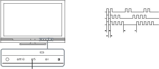
1-2. DISPLAY OF STANDBY/TIMER LIGHT FLASH COUNT
[ FLASH COUNT ] 2 times
4 times
5 times
|
LED ON 0.3 sec. |
|
|
|
|
|
|
|
|
|
|
|
|
|
|
|
|
|
LED OFF |
||||
|
LED OFF 0.3 sec. |
|
|
|
|
|
|
|
|||
|
|
|
|
|
|
|
|
|
2 sec. |
||
|
|
|
|
|
|
|
|
|
|
||
|
|
|
|
|
|
|
|
|
|
||
|
|
|
|
|
|
|
|
|
|
|
|
Note: One flash counts is not self-diagnostic.
STANDBY LED
1-3. STOPPING THE STANDBY FLASH
Turn off the power switch on the TV main unit or unplug the power cord from the outlet to stop the STANDBY LED from flashing.
KLV-32/40/46/52W400A (GA) 6
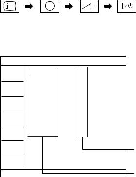
1-4. SELF-DIAGNOSTIC SCREEN DISPLAY
For errors with symptoms such as “power sometimes shuts off” or “screen sometimes goes out” that cannot be confirmed, it is possible to bring up past occurrences of failure for confirmation on the screen:
1-4-1. To Bring Up Screen Test
In standby mode, press buttons on the remote commander sequentially in rapid succession as shown below:
5
( Info/Text reveal ) ( Number button ) * ( Volume ) ( TV standby )
* : Note that this differs from entering the service mode (volume +)
[ SELF-DIAGNOSTIC SCREEN DISPLAY ]
TV
DC_DET |
0 |
DC_ALEAT1 |
0 |
DC_ALERT2 |
0 |
DC_ALERT3 |
0 |
BACKLIGHT |
0 |
TEMPERATURE |
0 |
AUDIO |
0 |
DFE |
0 |
B-ENGINE |
0 |
HFR |
0 |
|
|
Error Count Record
Number "0": means that no fault detected.
Number "1": means a fault was detected one time only.
Monitoring Items
For details, refer to "1-1. DIAGNOSTIC TEST INDICATORS"
Since the diagnostic results displayed on the screen are not automatically cleared, always check the self-diagnostic screen After you have completed the repairs, clear the result display to “0”.
1-5. Quitting Self-diagnostic screen
To quit the entire self-diagnostic screen, turn off the power switch on the remote commander or the main unit.
KLV-32/40/46/52W400A (GA) 7
TABLE OF CONTENTS
SAFETY CHECK-OUT ............................................. |
5 |
2. |
DIAGRAMS ..................................................... |
2-1 |
|||
|
|
|
|
2-1. |
CIRCUIT BOARDS LOCATION ......................... |
2-1 |
|
SELF DIAGNOSIS FUNCTION ................................ |
6 |
|
|
(1) |
KLV-32W400A ................................................ |
2-1 |
|
|
|
|
|
|
(2) |
KLV-40W400A ................................................ |
2-1 |
1. DISASSEMBLY ............................................... |
1-1 |
|
|
(3) |
KLV-46W400A ................................................ |
2-1 |
|
1-1. KLV-32W400A ...................................................... |
1-1 |
|
|
(4) |
KLV-52W400A ................................................ |
2-1 |
|
1-1-1. REAR COVER AND STAND ASSY |
|
|
2-2. |
BLOCK DIAGRAM .............................................. |
2-2 |
||
|
REMOVAL ...................................................... |
1-1 |
|
|
(1) |
BG1G Board ..................................................... |
2-2 |
1-1-2. SWITCH UNIT AND SIDE JACK BRACKET |
|
|
|
|
|
||
|
REMOVAL ...................................................... |
1-2 |
3. |
EXPLODED VIEWS ........................................ |
3-1 |
||
1-1-3. UNDER COVER AND VESA FRAME (TOP) |
|
3-1. KLV-32W400A ...................................................... |
3-2 |
||||
|
REMOVAL ...................................................... |
1-3 |
|
3-1-1. |
REAR COVER AND STAND ASSY ............. |
3-2 |
|
1-1-4. |
BG1G BOARD REMOVAL ........................... |
1-4 |
|
3-1-2. |
CHASSIS-1 ...................................................... |
3-3 |
|
1-1-5. |
POWER UNIT REMOVAL ............................ |
1-5 |
|
3-1-3. |
CHASSIS-2 ...................................................... |
3-4 |
|
1-1-6. SPEAKER AND UNDER BAR REMOVAL . 1-6 |
|
3-2. KLV-40W400A ...................................................... |
3-5 |
||||
1-1-7. LCD PANEL, H3E BOARD AND H4 BOARD |
|
3-2-1. |
REAR COVER AND STAND ASSY ............. |
3-5 |
|||
|
REMOVAL ...................................................... |
1-7 |
|
3-2-2. |
CHASSIS-1 ...................................................... |
3-6 |
|
1-1-8. |
WIRING LAYOUT ......................................... |
1-8 |
|
3-2-3. |
CHASSIS-2 ...................................................... |
3-7 |
|
1-2. KLV-40W400A ...................................................... |
1-9 |
|
3-3. KLV-46W400A ...................................................... |
3-8 |
|||
1-2-1. REAR COVER AND STAND ASSY |
|
|
3-3-1. |
REAR COVER AND STAND ASSY ............. |
3-8 |
||
|
REMOVAL ...................................................... |
1-9 |
|
3-3-2. |
CHASSIS-1 ...................................................... |
3-9 |
|
1-2-2. AC INLET AND UNDER COVER |
|
|
3-3-3. |
CHASSIS-2 .................................................... |
3-10 |
||
|
REMOVAL .................................................... |
1-10 |
|
3-4. KLV-52W400A .................................................... |
3-11 |
||
1-2-3. BG1G BOARD AND IP5 BOARD |
|
|
3-4-1. |
REAR COVER AND STAND ASSY ........... |
3-11 |
||
|
REMOVAL .................................................... |
1-11 |
|
3-4-2. |
CHASSIS-1 .................................................... |
3-12 |
|
1-2-4. |
FRAME REMOVAL ..................................... |
1-12 |
|
3-4-3. |
CHASSIS-2 .................................................... |
3-13 |
|
1-2-5. |
SPEAKER (L) REMOVAL ........................... |
1-13 |
|
3-5. |
PACKING MATERIALS .................................... |
3-14 |
|
1-2-6. |
SPEAKER (R) REMOVAL ........................... |
1-13 |
|
3-5-1. |
KLV-32W400A .............................................. |
3-14 |
|
1-2-7. LCD PANEL, H3E BOARD AND H4 BOARD |
|
3-5-2. |
KLV-40W400A .............................................. |
3-15 |
|||
|
REMOVAL .................................................... |
1-14 |
|
3-5-3. |
KLV-46W400A .............................................. |
3-16 |
|
1-2-8. |
WIRING LAYOUT ....................................... |
1-15 |
|
3-5-4. |
KLV-52W400A .............................................. |
3-17 |
|
1-3. KLV-46W400A .................................................... |
1-16 |
|
|
|
|
|
|
1-3-1. REAR COVER AND STAND ASSY |
|
|
|
|
|
|
|
|
REMOVAL .................................................... |
1-16 |
|
|
|
|
|
1-3-2. AC INLET AND UNDER COVER |
|
|
|
|
|
|
|
|
REMOVAL .................................................... |
1-17 |
|
|
|
|
|
1-3-3. BG1G BOARD AND IP5 BOARD |
|
|
|
|
|
|
|
|
REMOVAL .................................................... |
1-18 |
|
|
|
|
|
1-3-4. |
FRAME REMOVAL ..................................... |
1-19 |
|
|
|
|
|
1-3-5. |
SPEAKER (L) REMOVAL ........................... |
1-20 |
|
|
|
|
|
1-3-6. |
SPEAKER (R) REMOVAL ........................... |
1-20 |
|
|
|
|
|
1-3-7. LCD PANEL, H3E BOARD AND |
|
|
|
|
|
|
|
|
H4 BOARD REMOVAL ............................... |
1-21 |
|
|
|
|
|
1-3-8. |
WIRING LAYOUT ....................................... |
1-22 |
|
|
|
|
|
1-4. KLV-52W400A .................................................... |
1-23 |
|
|
|
|
|
|
1-4-1. REAR COVER AND STAND ASSY |
|
|
|
|
|
|
|
|
REMOVAL .................................................... |
1-23 |
|
|
|
|
|
1-4-2. AC INLET AND UNDER COVER |
|
|
|
|
|
|
|
|
REMOVAL .................................................... |
1-24 |
|
|
|
|
|
1-4-3. D4, D5, G5 AND BG1B BOARDS |
|
|
|
|
|
|
|
|
REMOVAL .................................................... |
1-25 |
|
|
|
|
|
1-4-4. |
FRAME REMOVAL ..................................... |
1-26 |
|
|
|
|
|
1-4-5. |
SPEAKER (L) REMOVAL ........................... |
1-27 |
|
|
|
|
|
1-4-6. |
SPEAKER (R) ................................................ |
1-27 |
|
|
|
|
|
1-4-7. LCD PANEL, H3E BOARD AND H4 BOARD |
|
|
|
|
|
||
|
REMOVAL .................................................... |
1-28 |
|
|
|
|
|
1-4-8. |
WIRING LAYOUT ....................................... |
1-29 |
|
|
|
|
|
|
|
|
|
|
|
KLV-32/40/46/52W400A (GA) |
8 |
SECTION 1
DISASSEMBLY
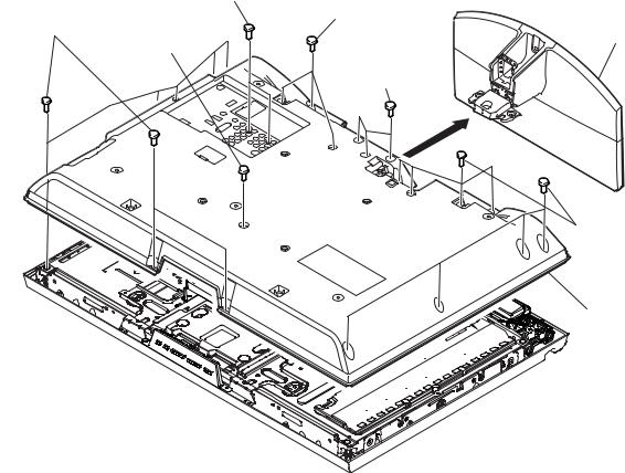
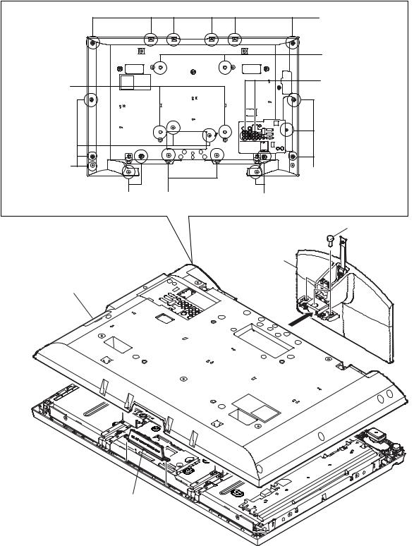
1-1. KLV-32W400A
1-1-1. REAR COVER AND STAND ASSY REMOVAL
5 Two screws |
|
|
(+BV 3X12, |
|
|
TYPE2, IT-3) |
|
|
3 Seven screws |
3 Three screws |
|
(+BVTP2 4X16) 4 One screws |
(+BVTP2 4X16) |
2 Stand assy |
(+PSW M5X8) |
|
|
|
|
|
|
1 Three screws |
|
|
(+PSW M5X16) |
|
3 Eight screws (+BVTP2 4X16)
6 Rear cover assy
KLV-32/40/46/52W400A (GA) 1-1
KLV-32W400A
1-1-2. SWITCH UNIT AND SIDE JACK BRACKET REMOVAL
2 Side jack |
Claw |
bracket assy |
1 Switch unit |
|
Claw
KLV-32/40/46/52W400A (GA) 1-2
KLV-32W400A
1-1-3. UNDER COVER AND VESA FRAME (TOP) REMOVAL
4 Two screws |
|
(+PSW M4X8) 3 Under cover |
2 Two screws |
|
(+BVST 3X8) |
5 VESA frame
(TOP) |
1 Power supply |
cord
KLV-32/40/46/52W400A (GA) 1-3
KLV-32W400A
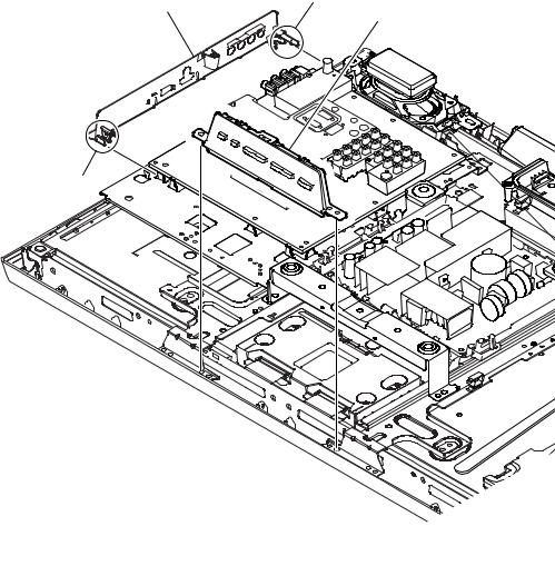
1-1-4. BG1G BOARD REMOVAL
3 One screw |
1 Four screws |
(+PSW M3x5) |
|
(+BVST 3X8) |
2 Two screws |
|
|
|
(SP 4-4O UNC) |
|
4 B (J) shield |
5 Four screws (+BVST 3X8)
5 Five screws (+BVST 3X8)
8 BG1G board
6 One screw (+BVST 3X8)
q; Main bracket assy
9 Two screws (+BVST 3X8)
7 Harness with connector (LVDS)
KLV-32/40/46/52W400A (GA) 1-4
KLV-32W400A
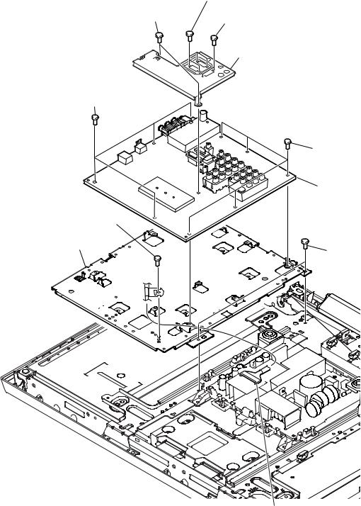
1-1-5. POWER UNIT REMOVAL
1 One screw
(+PSW M4X8) |
|
|
|
|
2 VESA frame |
|
|
5 Two screws |
(BOTTOM) |
|
|
5 Two screws |
|
||
(+PSW 3SG) |
|
||
(+PSW 3SG) |
3 One screw |
||
|
|||
|
|
||
|
|
(+PSW M4X8) |
6 Power unit
4 VESA frame (BOTTOM)
7 G1 brackt
Claw
KLV-32/40/46/52W400A (GA) 1-5
KLV-32W400A
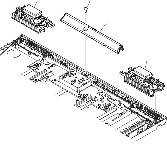
1-1-6. SPEAKER AND UNDER BAR REMOVAL
3 Loudspeaker |
1 Two screw |
|
|
|
(+BVTP2 4X16) |
|
2 Under bar |
4 Loudspeaker
KLV-32/40/46/52W400A (GA) 1-6

KLV-32W400A
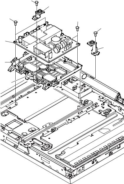
1-1-7. LCD PANEL, H3E BOARD AND H4 BOARD REMOVAL
2 Two screws |
3 Spine frame (L)assy |
||
(+PSW M4X8) |
|||
|
5 Three screws |
||
1 One screw |
|
||
|
(+PSW M4X8) |
||
(+BVTP2 4X16) |
|
|
|
|
7 two screws |
6 Spine frame (R)assy |
|
|
8 Two screws |
||
|
(+PSW M4X8) |
||
|
|
(+BVTP2 4X16) |
|
|
|
7 Two screws |
|
|
|
(+PSW M4X8) |
|
|
|
9 Vesa frame assy |
|
4 One screw |
|
q; One screw |
|
|
(+BVTP 3X12 TYPE2 IT-3) |
||
(+BVTP2 4X16) |
|
||
|
|
||
|
|
qa H4 board |
|
|
|
Claw |
|
|
|
qs Light guide |
|
|
|
qd H3E board |
|
qf Claer panel
qh Two screws (+BVTP2 4X16)
qj LCD panel
qg Illumination module
qk Bezel assy
KLV-32/40/46/52W400A (GA) 1-7
KLV-32W400A
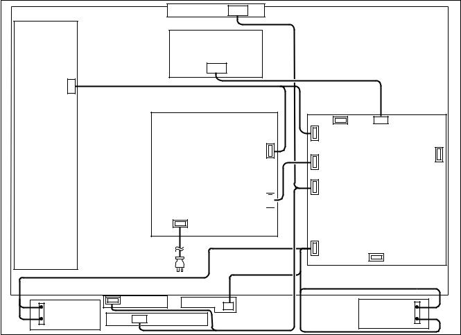
1-1-8. WIRING LAYOUT
SWITCH Unit
CN001
Inverter
CN601
Power Unit
CN602 


|
|
Power |
|
|
|
cord |
|
|
CN401 |
|
|
|
H4 board |
Illumination |
|
|
|
|
|
Speaker (L) |
CN301 |
H3E board |
module |
|
|
||
CN4001 |
CN4000 |
CN5501 |
|
|
CN8001 |
CN5500 |
|
CN3004 |
BG1G board |
CN2001 |
CN3003 |
Speaker (R)
KLV-32/40/46/52W400A (GA) 1-8
1-2. KLV-40W400A
1-2-1. REAR COVER AND STAND ASSY REMOVAL
 3 Six screws (+BVTP2 4X16)
4 Two screws (+PSW M5X8)
4 Two screws |
|
(+PSW M5X8) |
|
3 Five screws |
|
(+BVTP2 4X16) |
|
3 Two screws |
5Two screws |
(+BVTP2 4X16) |
(+PSW M5X12) |
6 Two screws (+BV 3X12, TYPE2, IT-3)
 3 Four screws (+BVTP2 4X16)
3 Two screws (+BVTP2 4X16)
1 Three screws (+PSW M5X12)
2 Stand assy
7 Rear cover assy
8 Switch unit
KLV-32/40/46/52W400A (GA) 1-9

KLV-40W400A
1-2-2. AC INLET AND UNDER COVER REMOVAL
2 Under bar (L)
1 Two screws (+BVTP2 4X16)
7 Two screws (+BVST 3X8)
8 AC inlet bracket |
5 Two screws |
|
(+KTT 3X10(S TYPE)) |
||
|
3 One screw (+BVST 3X8)
6 AC inlet
4 Under cover (L2)
KLV-32/40/46/52W400A (GA) 1-10
Loading...