


KLV-22T550A
Table of contents
 Loading...
REVISION HISTORY
NO. SUFFIX DATE SUPP / CORR DESCRIPTION
1 -01 2009/06 _ _ 1st Issue
EX2T
CHASSIS
MODEL
KLV-22T550A
KLV-32T550A
PART NO.: 9-888-120-01
CHASSIS
SERVICE MANUAL
MODEL COMMANDER DEST.
KLV-22T550A
RM-GA016 ARM, India, Indonesia,
Malaysia,New Zealand,
Phillipines, Saudi
Arabia, Singapore,
SOGUL , Thailand,
Vietnam
KLV-32T550A
RM-GA016 ARM, India,
Indonesia, Iran,
Malaysia, Phillipines,
Saudi Arabia,
Singapore, SOGUL,
South Africa,
Thailand, Vietnam
EX2T
KLV-22T550A
MODEL COMMANDER DEST.
RM-GA016
KLV-32T550A
LCD COLOR TV

– 2 –
KLV-22, 32 T550A
RM-GA016
TABLE OF CONTENTS
1. SAFETY NOTES
1-1. Caution Handling of LCD Panel ..................................... 3
1-2. Safety Check Out.............................................................3
1-3. Leakage Test .................................................................... 3
1-4. WARNING ! .................................................................... 3
1-5. Lead Free Information..................................................... 4
1-6. Attachment & Detachment of JST IBH Connector ....... 4
2. SELF DIAGNOSTIC FUNCTION
2-1. Overview of Control Buttons .......................................... 6
2-2. LED Display Specification..............................................6
2-3. LED Display Control.......................................................6
2-4. LED Pattern .....................................................................6
2-5. Viewing the Service Diagnosis Display..........................6
2-6. Standby LED Error Display ............................................7
2-7. Triage Chart ..................................................................... 8
3. TROUBLE SHOOTING
3-1. FlowChart ........................................................................9
3-2. Board Replacement Order ............................................. 10
4. DISASSEMBLY
4-1. KLV-22T550A ...............................................................11
4-2. KLV-32T550A ...............................................................12
5. WIRE DRESSING
5-1. KLV-22T550A ...............................................................14
5-2. KLV-32T550A ...............................................................16
Section Title P a g e
Section Title Pa ge
6. SERVICE ADJUSTMENTS
6-1. Accessing Diagnostic Menu..........................................18
6-2. Viewing the Service Mode Display .............................. 18
6-3. Control Keys Via Remote Commander.........................18
6-4. Adjustment Method ....................................................... 18
6-5. Table 1............................................................................20
7. DIAGRAMS
7-1. Block Diagram............................................................... 21
7-2. Connector Diagram ....................................................... 28
7-3. Circuit Board Location .................................................. 29
7-4. Schematic Diagram ........................................................ 29
7-5. Printed Wiring Boards ................................................... 29
7-6. Semiconductor ............................................................... 29
8. EXPLODED VIEWS
8-1. KLV-22T550A ...............................................................30
8-2. KLV-32T550A ...............................................................32
9. ELECTRICAL PARTS LIST
9-1. KLV-22T550A ...............................................................34
9-2. KLV-32T550A ...............................................................35
OPERATING INSTRUCTIONS
– 3 –
KLV-22, 32 T550A
RM-GA016
1-1. Caution Handling of LCD Panel
When installing the LCD Panel, make sure you are grounded
with a wrist band.
When installing the LCD Panel on the wall, the panel must be
secured using the 4 mounting holes on the rear cover.
1) Do not press the panel or frame edge to avoid the risk of
electric shock.
2) Do not scratch or press on the panel with any sharp
objects.
3) Do not leave the module in high temperature or in areas of
high humidity for an extended period of time.
4) Do not expose the LCD panel to direct sunlight.
5) Avoid contact with water. It may cause short circuit within
the module.
6) Disconnect the AC adapter when replacing the backlight
(CCFL) or inverter circuit. (High voltage occurs at the inverter
circuit at 650Vrms)
7) Always clean the LCD panel with a soft cloth material.
8) Use care when handling the wires or connectors of the
inverter circuit. Damaging the wires may cause a short circuit.
9) Protect the panel from ESD to avoid damaging the elec-
tronic circuit (C-MOS).
1-2. Safety Check-Out
After correcting the original service problem, perform the
following safety checks before releasing the set to the
customer:-
1) Check the area of your repair for unsoldered or poorly
soldered connections. Check the entire board surface for
solder splashes and bridges.
2) Check the interboard wiring to ensure that no wires are
"pinched" or contact high-wattage resistors.
3)Check all control knobs, shields, covers, ground straps and
mounting hardware have been replaced. Be absolutely certain
you have replaced all the insulators.
4) Look for unauthorized replacement parts, particularly
transistors that were installed during a previous repair. Point
them out to the customer and recommend their replacement.
5) Look for parts which, though functioning show obvious
signs of deterioration. Point them out to the customer and
recommend their replacement.
6) Check the line cords for cracks and abrasion.
Recommend the replacement of any such line cord to the
customer.
7) Check the antenna terminals, metal trim, "metallized"
knobs, screws and all other exposed metal parts for AC
leakage. Check leakage test as described next.
1-3. Leakage Test
The AC leakage from any exposed metal part to earth
ground and from all exposed metal parts to any exposed
metal part having a return to chassis must not exceed 0.5mA
(500 microamperes). Leakage current can be measured by
any one of the three methods:-
1. A commercial leakage tester such as the SIMPSON 229 or
RCA WT-540A. Follow the manufacturers instructions to use
those instructions.
2. A battery-operated AC milliampmeter. The DATA
PRECISION 245 digital multimeter is suitable for this job.
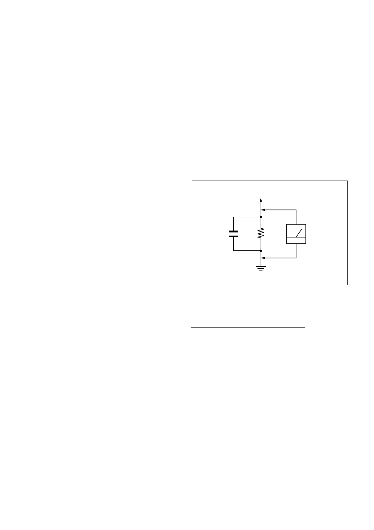
3. Measuring the voltage drop across a resistor by means of
a VOM or battery operated AC voltmeter. The 'limit' indication
is 0.75V so analog meters must have an accurate low voltage
scale. The SIMPSON'S 250 and SANWA SH-63TRD are
examples of passive VOMs that are suitable. Nearly all battery
operated digital multimeters that have a 2 VAC range are
suitable. (see Figure 1.)
1.5 k
Ω
0.15 µF
AC
Voltmeter
(0.75 V)
To Exposed Metal
Parts on Set
Earth Ground
SECTION 1
SAFETY NOTES
Figure 1. AC voltmeter to check AC leakage
1-4. W ARNING !
SAFETY-RELATED COMPONENT WARNING!
COMPONENTS IDENTIFIED BY SHADING AND MARK !
ON THE EXPLODED VIEWS ARE CRITICAL FOR SAFE
OPERATION. REPLACE THESE COMPONENTS WITH
SONY PARTS WHOSE PART NUMBERS APPEAR AS
SHOWN IN THIS MANUAL OR IN SUPPLEMENTS
PUBLISHED BY SONY. CIRCUIT ADJUSTMENTS THAT ARE
CRITICAL FOR SAFE OPERATION ARE IDENTIFIED IN
THIS MANUAL. FOLLOW THESE PROCEDURES
WHENEVER CRITICAL COMPONENTS ARE REPLACED
OR IMPROPER OPERATION IS SUSPECTED.
– 4 –
KLV-22, 32 T550A
RM-GA016
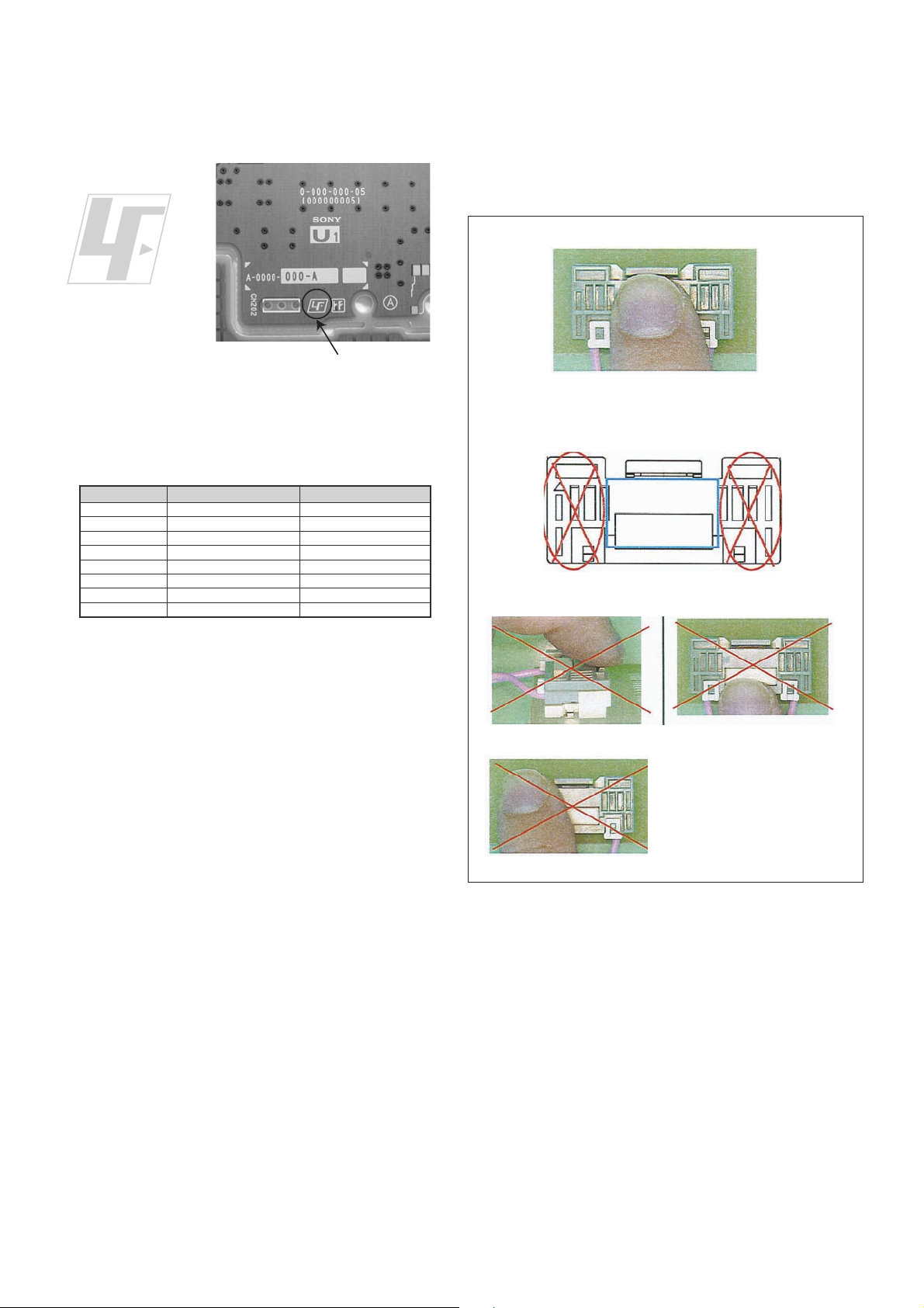
1-5. Lead Free Information
The circuit boards used in these models have been processed
using Lead Free Solder. The boards are identified by the LF
logo located close to the board designation.
The servicing of these boards requires special precautions. It
is strongly recommended to use Lead Free Solder material in
order to guarantee optimal quality of new solder joints. Lead
Free Solder is available under the following part numbers:-
Due to high melting point of Lead Free Solder, the soldering
iron tip temperature needs to be set to 370 degrees
centigrade. This requires soldering equipment capable of
accurate temperature control coupled with a good heat
recovery characteristics.
For more information on the use of Lead Free Solder,
please refer to
http://www.sony-training.com
rebmuntraP retemaiD skrameR
91-500-046-mm
m
m
m
m
m
m
m
3.0Kg52.0
02-500-046-7m4.0Kg05.0
12-500-046-7m5.0Kg05.0
22-500-046-7m6.0Kg52.0
32-500-046-7m8.0Kg00.1
42-500-046-7m0.1Kg00.1
52-500-046-7m2.1Kg00.1
62-500-046-7m6.1Kg00.1
7
Figure 2: LF logo
Figure 3: LF logo on circuit board
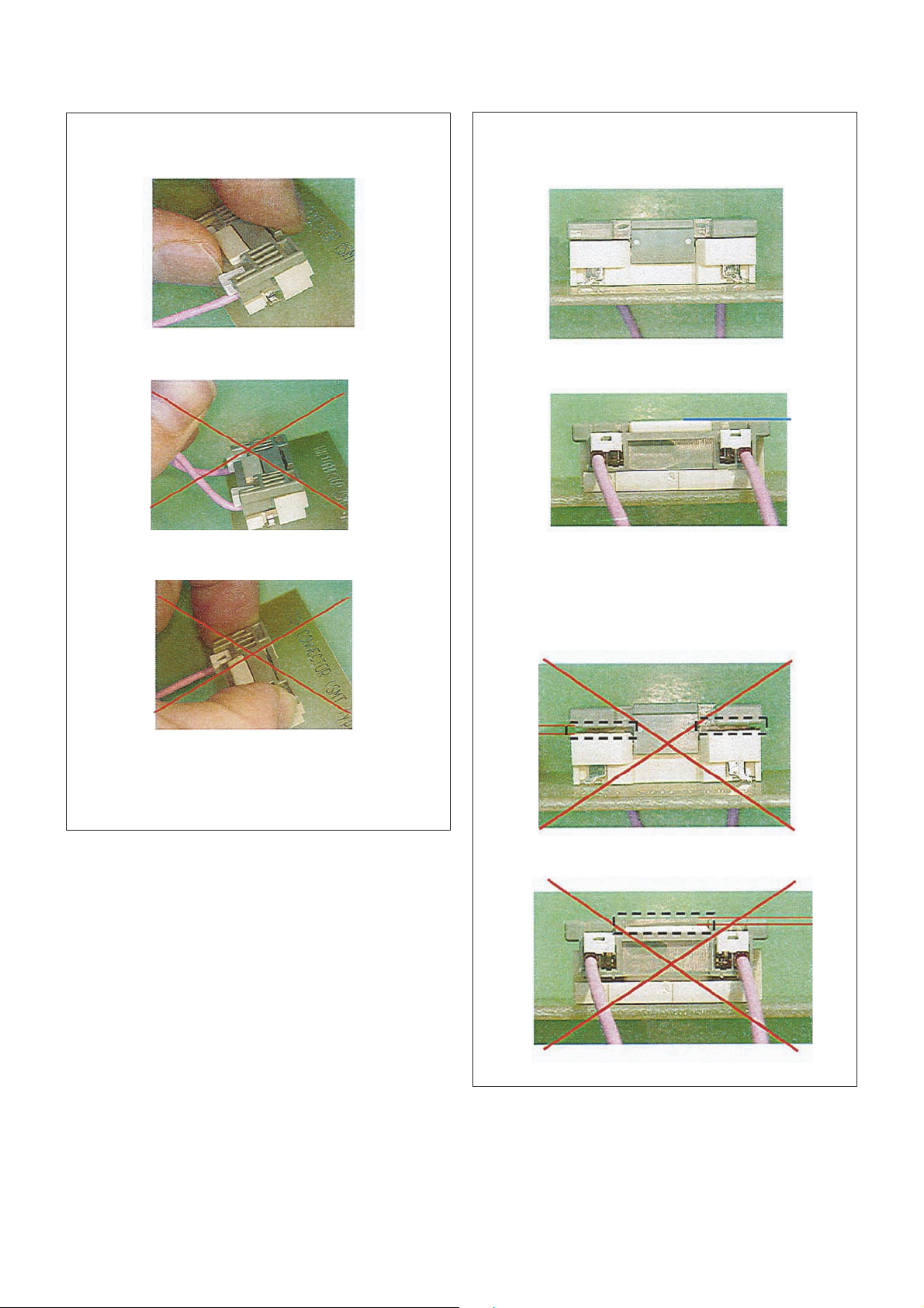
1-6. Attachment, Detachment & Confirmation of Lock
Condition of JST IBH Connector
(If applicable for these models)
Attention: This is a SAFETY CRITICAL PROCESS.
a) Attachment
(1) Press the center of the connector to insert it.
(2) Press position
(NG for red marking portion)
(3) Prohibited matter (Refer Figure A~C explanation)
Figure A
Figure B
Figure C
Figure A: Do not press lock
portion.
Figure B: Do not press the
front side of the
connector.
Figure C: Do not press the side
of the connector.
– 5 –
KLV-22, 32 T550A
RM-GA016
b) Detachment
(1) Hold between the lock part and harness of socket.
Release the lock and pull out connector within 20
degree.
(2) Prohibited matter (Refer Figure D & E explanation)
Figure D: Do not pull out by holding the harness only.
Figure E: Do not pull out the connector when it does not
release the lock.
Figure D
Figure E
Figure F
Figure G
c) Confirmation of Lock Condition
(1) Confirm the lock conditions. When lock is completed,
base and socket must be same line as shown in Figure
F and G.
(2) NG Condition
It is NG condition when there are some gap between
base and socket such as in Figure H and I.
Figure H
Figure I
Gap
Gap
– 6 –
KLV-22, 32 T550A
RM-GA016
LED Type Description
Remark
Status
Display
Power LED
Remark
POWER Green: One LED
Green lights at power ON.
STANDBY Red: One LED Red lights during standby.
Timer
Orange
: One Led
Amber lights
during Timer activation.
POWER ON
Timer LED
Green lights
OFF
in a normal state.
STANDBY
OFF
OFF
Red lights
Wake up
timer-ON
Sleep timer-ON
Wake up
timer-ON
Sleep timer-OFF
Failure-OFF
Red flashes
LOCTOP is
in a sleep state.
Failure
Classify the
trouble causes by
the no. of red
blinking.
Standby LED
LOCTOP is
SECTION 2
SELF DIAGNOSTIC FUNCTION
2.0 sec 2.0 sec
0.3 sec
0.3 sec
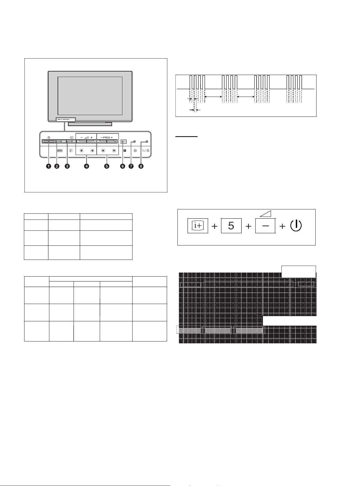
2-1. Overview of Control Buttons
2-2. LED Display Specification
2-3. LED Display Control
2-4. LED Pattern
When safety shutdown occurs, Standb y LED display reports the
cause by using the blinking patterns as indicated below.
Example:
The figure above shows LED display when
SHUTDOWN is caused by audio failure. It repeats
flashing for a specified number of times in 0.3sec/
cycle and has a 2 seconds interval of lighting off.
Please note that a 2 seconds interval of lighting off
is fixed regardless of abnormal state types.
2-5. Viewing the Service Diagnosis Display
1. While TV on standby mode, press the following sequence on
the Remote commander.
(if wrong key is pressed or passed 3 seconds during each
process, cancel entering the self-diagnosis display.)
2. To Exit, press the <I/1> key.
Addtional information:
1. To refresh History of Error Note:
--> press < 8 > --> < 0 > key.
2. To refresh Histry of Panel Operation Time.
-->press < 7 > --> < 0 > key
On screen
display
Channel 5
Volume (-)
POWER
S E L F C H E C K
0 0 2 M A I N _ P O W E R _ E R R O R
0 0
0 0 4 5 V _ P O W E R _ E R R O R 0 0
0 0 6 B A C K _ L I G H T _ E R R O R 0 0
0 0 7 T E M P _ E R R O R 0 0
0 0 8 A U D I O _ E R R O R 0 0
1 2 3 4 5 - 0 9 8 7 6 - 0 1 2 3 4
12345: Total operation time by hour (0-65535)
09876: Boot count (0-65535)
01234: Panel operation time by hour (0-65535)
002: LED blinking times
MAIN_POWER_ERROR:
Detection name
00: Error Count (00-99)
Power
Menu
Input
Select
Volume
Channel
Remote
Sensor
Timer
Indicator
Power/
Standby
Indicator
* Sleep timer is cancelled once TV goes to standby.
– 7 –
KLV-22, 32 T550A
RM-GA016
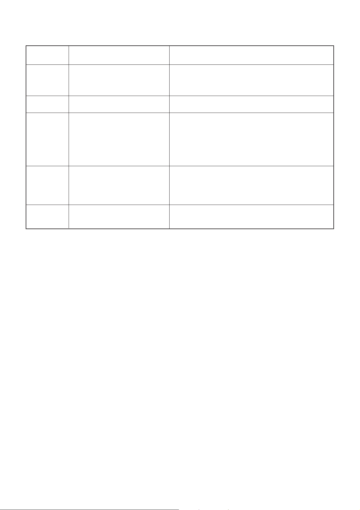
2-6. STANDBY LED ERROR DISPLAY
Blinking times Detection items Countermeasure
2 Main power failure Replace either/both z BT2 board
z GT2 board (22”)
z GT3 board (32”)
4 5V power failure Replace BT2 board.
8Audio failure Replace either/board.
z BT2 board
z GT2 board (22”)
z GT3 board (32”)
z Speaker
z Woofer
6 Back light failure Replace either/board.
z BT2 board
z GT2 board (22”)
z GT3 board (32”)
7 Internal temperature Replace either/both z GT2 board (22”)
failure z GT3 board (32”)
Note: Each of the above blinking repeats every 2 seconds.
– 8 –
KLV-22, 32 T550A
RM-GA016
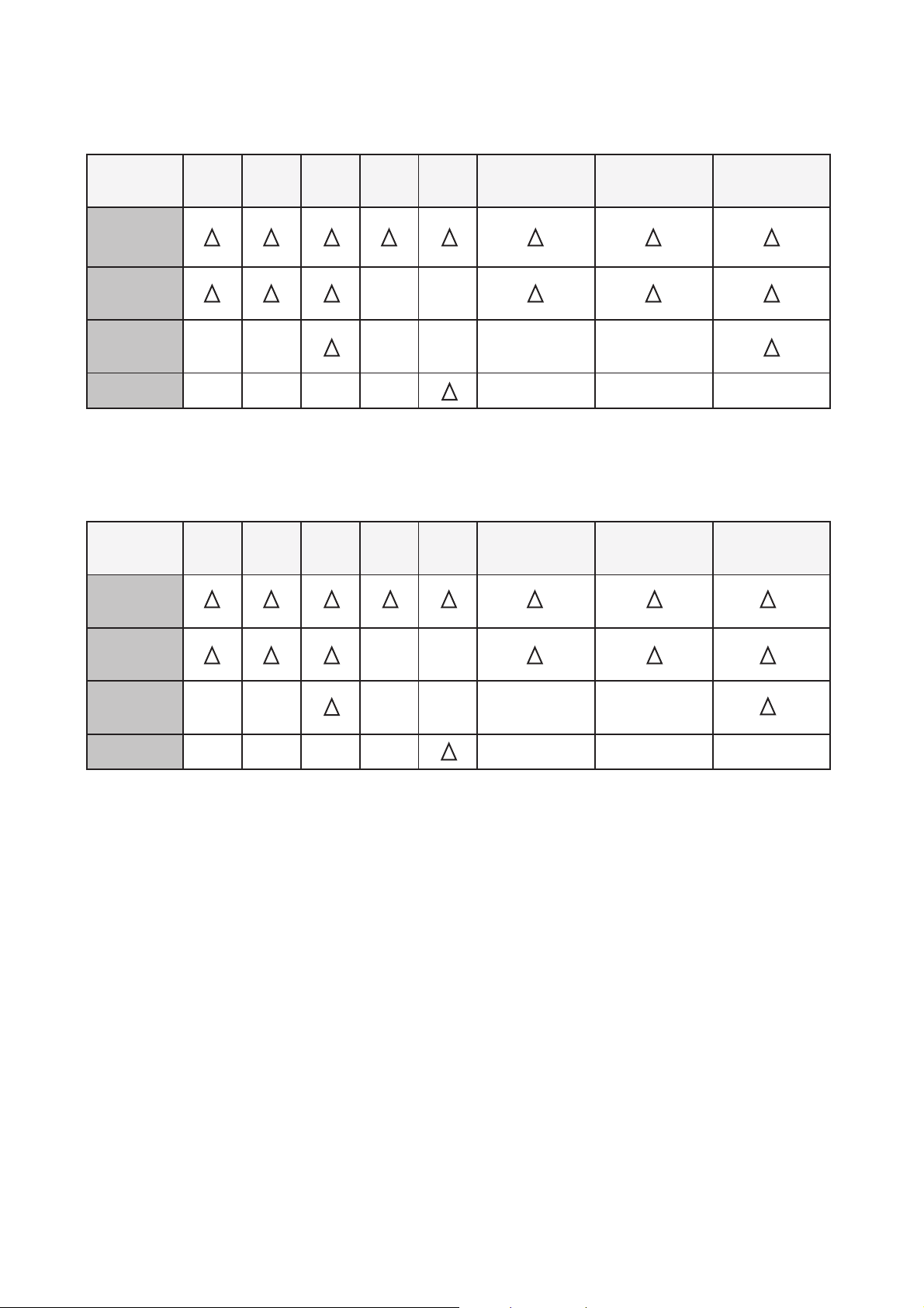
2-7. T riage Chart
2-7-1. KLV-22T550A
2-7-2. KLV-32T550A
Panel
GT2
Sound NG Picture NG
BT2
7x 8x No Power
Failure
2x 4x 6x
Failure
2x 4x 6x 7x 8x No Power Sound NG Picture NG
BT2
GT3
Panel
Speaker
Speaker
– 9 –
KLV-22, 32 T550A
RM-GA016
PICTURE NG
All input have
problem
BT2 Board NG
NO
YES
LVDS harness connection
or BT2 board or Panel NG
BT2 Board or GT2, GT3 Board NG
NO
YES
Backlight on?
UI of some picture
setting correct?
Set correctly or reset by menu
YES
NO
SECTION 3
TROUBLESHOOTING
3.1 Flowchart
NO
Check AC cable
connection
BT2 NG
AC cable NG
No Power
STBY_VCC
(GT2:13.2V, GT3:6.2V)
CN7000_7pin on BT2
YES
YES
YES
GT2 or GT3 Board NG
NO
Sound NG
Only speaker out?
BT2 Board NG
UI of Audio
setting
correct?
Volume,TV speaker
NO
YES
Set correctly or reset by menu
BT2 Board or Speaker NG
NO
YES
AUDIO_VCC
(GT2:1, GT2:10V, GT3:13V)
CN7000_1, 2pin on
NO
YES
GT2 or GT3 Board NG
Trouble Shooting Flowchart
1. NO POWER 2. SOUND NG
3. PICTURE NG

– 10 –
KLV-22, 32 T550A
RM-GA016
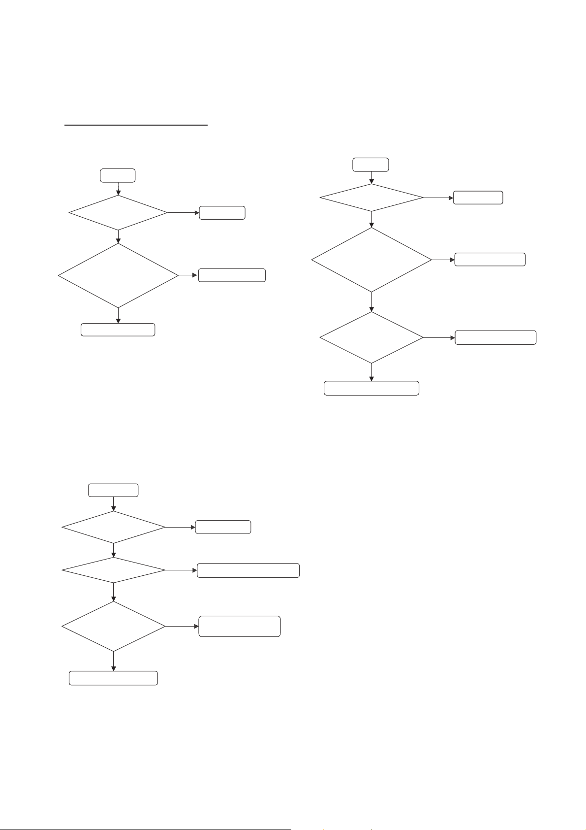
3.2 Board Replacement Order
Finish
LED 2x or 4 x BLINKING
GT2 or
GT3
Replace(OK)
NO
Replace BT2
3.2.1. LED 2x or 4x BLINKING
NO
Speaker
Replace(OK)
Replace BT2 Finish
LED 8x BLINKING
3.2.2. LED 8x BLINKING
BT2
Replace(OK)
Replace Panel Module
Finish
LED 6x BLINKING
Replace(OK)
GT2 or
GT3
3.2.3. LED 6x BLINKING 3.2.4. LED 7x BLINKING
NO
BT2
Replace(OK)
Finish
LED 7x BLINKING
Replace Panel Module
Loading...