


 Loading...
HISTORY INFORMATION FOR THE FOLLOWING MANUAL:
SERVICE MANUAL (COMMON)
RB2G CHASSIS
Segment: XM-L
Version |
Date |
Subject |
1 |
3/2015 |
1st Issue. |
LCD TV
9-888-170-01
For SM - Unique , please refer :
9-888-170-Ax ( America ) 9-888-170-Jx ( Japan )
9-888-170-Ex ( Europe )
9-888-170-Px ( Pan Asia )

SERVICE MANUAL (COMMON)
RB2G CHASSIS
Segment: XM-L
LCD TV

MODEL LIST
THIS SERVICE MANUAL CONTAINS COMMON INFORMATION FOR BELOW REGIONS AND MODELS:
REGION
ASIA JAPAN AMERICA EUROPE
MODEL
KJ-32W7*C KDL-32W7*C
KJ-40W7*C KDL-40W7*C
KJ-48W7*C KDL-48W7*C
3

TABLE OF CONTENTS
Section Title |
Page |
|
1. SAFETY NOTES |
|
|
1-1. |
Warnings and Caution………………………………………………………. |
5 |
1-2. |
Caution Handling of LCD Panel ......…………….................................... |
5 |
1-3. |
Caution About the Lithium Batter………………………………………….. |
6 |
1-4. |
Safety Check Out ........................……………......................................... |
6 |
1-5. |
Leakage Test .......................................................................................... |
6 |
1-6. |
How to Find a Good Earth Ground………………………………………… |
7 |
1-7. |
Lead Free Information….…………………………………………………… |
7 |
1-8. |
Handling the Flexible Flat Cable (FFC)……………………………………. |
7 |
2. SELF DIAGNOSTIC FUNCTION |
|
|
2-1. |
Overview of Control Buttons ................................................................... |
8 |
2-2. |
LED Display Control ………..................................................................... |
9 |
2-3. |
LED Pattern………………........................................................................ |
9 |
2-4. |
Standby LED Error Display…………………………………………………. |
9 |
2-5. |
Triage Chart ............................................................................................ |
10 |
3. TROUBLE SHOOTING |
|
|
3-1. |
No Power…….……………………………………………………………….. |
11 |
3-2. |
LED Blinking……………….………………………………………............... |
12 |
3-3. |
No Sound……………………………......................................................... |
20 |
3-4. |
No Picture................................................................................................. |
21 |
3-5. |
Side Buttons Malfunction……………………………………………………. |
23 |
3-6. |
IR Remote Commander Malfunction……………………………………… |
23 |
3-7. |
Light Sensor Error…………………………………………………………. |
23 |
3-8. |
Network Malfunction: Ethernet (Wired)……………………………………. |
24 |
3-9. |
3D-Glasses (Active) malfunction………………………………………….. |
25 |
3-10. |
Wireless Network Malfunction……………………………………………. |
26 |
3-11. |
Bluetooth Malfunction……………………………………………………….. |
27 |
Section Title |
|
Page |
4. SERVICE ADJUSTMENTS |
|
|
4-1. |
Accessing Service Mode ..................................................................... |
28 |
4-2. |
Transition of Each Micro’s Service Mode……….……………………… |
28 |
4-3. |
Change Data by Service Mode 1…………………………………..……. |
28 |
4-4. |
Change Data by Service Mode 2………………………………………... |
29 |
4-5. |
Restore WB / Gamma Adj. Data to B Board.………………………….. |
31 |
4-6. |
WB Adjustment by Service Mode……………………………………….. |
32 |
4-7. |
VCOM Adjustment (NFR-AUO/SDC/FXC Panel) …………………………… |
33 |
4-8. |
VCOM Adjustment (HFR-AUO /FXC Panel) …………………………………. |
33 |
4-9. |
REC Setting………………………………………................................... |
33 |
4-10. |
Reset Panel Operation Time………………………………………......... |
34 |
4-11. |
Set to Shipping Condition……………………………………….............. |
34 |
4-12. |
Summary of Service Control……………………………………….......... |
34 |
4-13. |
Service Menu Tree………………………………………........................ |
35 |
4-14. |
How to Enter Self Diagnosis Display…………………………………… |
36 |
5. DIAGRAMS |
|
|
5-1. |
Circuit Board Location ......................................................................... |
38 |
5-2. |
Block Diagram ………………………………………...................... |
38 |
5-3. |
Connector Diagram ………………………………………...................... |
46 |
Please refer Service Manual – Unique for below information : -Safety Warnings
-Wire Dressing -Circuit Board Location
-Disassembly and Exploded View.
4

SECTION 1
SAFETY NOTES
1-1. Warnings and Caution
1)These servicing instructions are for use by qualified service personnel only.
2)To reduce the risk of electric shock, do not perform any servicing other than that contained in the operating instructions unless you are qualified to do so.
3)An isolation transformer should be used during any service to avoid Possible shock hazard, because of live chassis. The chassis of this receiver is directly connected to the ac power line.
4)Be sure to follow these guidelines to protect your property and
avoid causing serious injury :
•Carry the TV with an adequate number of people; larger size TVs require two or more people.
•Correct hand placement while carrying the TV is very important for safety and to avoid damages.
5) Components identified by shading and ! mark on the exploded views, and in the parts list are critical for safe operation. Replace these components with Sony parts whose part numbers appear as shown in this manual or in supplements published by Sony. Circuit adjustments that are critical for safe operation are identified in this manual. Follow these procedures whenever critical components are replaced or improper operation is suspected.
1-2. Caution Handling of LCD Panel
When repairing the LCD Panel, make sure you are grounded with a wrist band. When repairing the LCD Panel on the wall, the panel must be secured using the 4 mounting holes on the rear cover.
1)Do not press the panel or frame edge to avoid the risk of electric shock.
2)Do not scratch or press on the panel with any sharp objects.
3)Do not leave the module in high temperature or in areas of high humidity for an extended period of time.
4)Do not expose the LCD panel to direct sunlight.
5)Avoid contact with water. It may cause short circuit within the module.
6)Disconnect the AC power when replacing the backlight (CCFL) or
inverter circuit. (High voltage occurs at the inverter circuit at 650Vrms)
7)Always clean the LCD panel with a soft cloth material.
8)Use care when handling the wires or connectors of the inverter circuit. Damaging the wires may cause a short circuit.
9)Protect the panel from ESD to avoid damaging the electronic circuit (C-MOS).
10)During the repair, DO NOT leave the Power On or Burn-in period for more than 1 hour while the TV is face down on a cloth.
Figure 1. TV is faced down on a cloth during repair.
5

Safety Notes
1-3. Caution About the Lithium Battery |
|
|
|
|
|
|
|
|
|
1) Danger of explosion if battery is incorrectly replaced. Replace only with |
|
|
|
|
the same or equivalent type. |
3) Measuring the voltage drop across a resistor by means of a VOM or battery |
|||
2) Outer case broken battery should not contact to water. |
operated AC voltmeter. The 'limit' indication is 0.75V so analog meters must |
|||
1-4. Safety Check-Out |
have an accurate low voltage scale. The SIMPSON'S 250 and SANWA SH- |
|||
63TRD are examples of passive VOMs that are suitable. Nearly all battery |
||||
After correcting the original service problem, perform the following |
||||
operated digital multimeter that have a 2 VAC range are suitable. |
||||
safety checks before releasing the set to the customer:- |
||||
(see Figure 2.) |
||||
1)Check the area of your repair for unsoldered or poorly soldered connections. Check the entire board surface for solder splashes and bridges.
2)Check the inter board wiring to ensure that no wires are pinched or
contact high-wattage resistors. |
|
|
|
|
|
|
||||
3)Check all control knobs, shields, covers, ground straps and mounting |
|
|||||||||
hardware have been replaced. Be absolutely certain you have replaced all |
|
|||||||||
the insulators. |
|
|
|
|
|
|
|
|
|
|
4) Look for unauthorized replacement parts, particularly transistors that |
|
|
||||||||
were installed during a previous repair. Point them out to the customer and |
Figure 2. AC voltmeter to check AC leakage |
|||||||||
recommend their replacement. |
|
|
|
|
|
|||||
|
|
|
|
|
1-6. How to Find a Good Earth Ground |
|||||
5) Look for |
parts |
which, |
though |
functioning show |
obvious signs |
of |
||||
1) A cold-water pipe is a guaranteed earth ground; the cover-plate retaining |
||||||||||
deterioration. |
Point |
them |
out |
to |
the |
customer and |
recommend their |
|||
screw on most AC outlet boxes is also at earth ground. |
||||||||||
replacement. |
|
|
|
|
|
|
|
|
||
|
|
|
|
|
|
|
|
2) If the retaining screw is to be used as your earth ground, verify that it is at |
||
6) Check the line |
cords |
for |
cracks |
and abrasion. Recommend |
the |
|||||
ground by measuring the resistance between it and a cold-water pipe with an |
||||||||||
replacement of any such line cord to the customer. |
|
|
||||||||
|
|
ohmmeter. The reading should be zero ohms. |
||||||||
7) Check the antenna terminals, metal trim, metalized knobs, screws and all |
||||||||||
3) If a cold-water pipe is not accessible, connect a 60to 100-watt trouble- |
||||||||||
other exposed metal parts for AC leakage. Check leakage test as described |
||||||||||
light (not a neon lamp) between the hot side of the receptacle and the |
||||||||||
next. |
|
|
|
|
|
|
|
|
||
|
|
|
|
|
|
|
|
retaining screw. Try both slots, if necessary, to locate the hot side on the line; |
||
8. For safety reasons, repairing the Power board and/or Inverter board is |
||||||||||
the lamp should light at normal brilliance if the screw is at ground potential |
||||||||||
prohibited. |
|
|
|
|
|
|
|
|
||
|
|
|
|
|
|
|
|
(see Figure 3). |
||
1-5.Leakage Test |
|
|
|
|
|
|
|
|||
|
|
|
|
|
|
|
|
|||
The AC leakage from any exposed metal part to earth ground and from all |
|
Figure 3. Checking for earth |
||||||||
exposed metal parts to any exposed metal part having a return to chassis must |
||||||||||
not exceed 0.5mA (500 microamperes). |
|
|
|
ground. |
||||||
Leakage current can be measured by any one of the three methods:- |
|
|
||||||||
1)A commercial leakage tester such as the SIMPSON 229 or RCA WT540A. Follow the manufacturers instructions to use those instructions.
2)A battery-operated AC milliampmeter The DATA PRECISION 245 digital multimeter is suitable for this job.
6
Safety Notes
1-7. Lead Free Information
The circuit boards used in these models have been processed using Lead Free Solder. The boards are identified by the LF logo located close to the board designation.
Figure 4: LF Logo |
Figure 5: LF logo on circuit board |
The servicing of these boards requires special precautions. It is strongly recommended to use Lead Free Solder material in order to guarantee optimal quality of new solder joints.
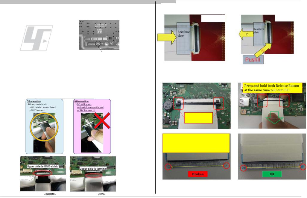
1-8. Handling the FLEXIBLE FLAT CABLE (FFC)
When you insert / pull out FFC, please grasp a reinforcement board and main body of FFC.
Please hold reinforcement board and plunge it to depths.
Main Board
< Insertion>
Release Button
of Connector
FFC connector broken if pull out FFC without press and hold both Release Button of connector. Symptom 5X blinking will be appear due to improperly seated.
Please pull out FFC while pushing the button of both ends at the same time.
Main Board
<Pull out>
7

Self Diagnostic Function
|
|
SECTION 2 |
||
|
|
SELF DIAGNOSTIC FUNCTION |
||
2-1. Overview of Control Buttons |
|
|
|
|
2-1-1. |
|
|
|
|
|
|
|
|
|
|
FRONT |
TV CONTROLS/ TERMINALS/ INDICATOR |
||
Remote Control Sensor /
Light sensor / * Illumination LED/ 3D
Sync Transmitter
Illumination lights up or blinks in different colours according to the status of the TV
( details refer to 2-2. LED Display Control
REAR OF TV
HOME
Press to display the TV Home Menu.
Power
Turn the TV on or switch to standby mode
CH+/- (Channel) / |
/ , |
+/- (Volume) / |
/ . |
Press to select the next or previous channel.
Press to adjust the volume.
In TV Home Menu: buttons will work as , , , .
INPUT SELECT / SELECT/ CONFIRM
Press to select the next or previous channel.
In TV Home Menu: buttons will work as (select/confirm)
8
Self Diagnostic Function
|
2-2. LED Display Control |
|
|
|
|
|
|
|
|
|
|
|
|
|
|
|
|
|
|
|
|
|
2-4. Standby LED Error Display |
|
|
|
|
|
|
|
|
|
|||||||||||||||
|
|
|
|
|
|
|
|
|
|
White Center |
|
|
|
|
|
|
|
|
|
|
|
|
|
|
|
|
|
|
|
|
|
|
|
|
|
|
|
|
|
|
|
|
|
|
|||
|
|
Status |
|
|
|
|
|
LED |
Side RGB LED |
Side Amber |
Remarks |
|
|
Smart |
|
|
|
|
|
|
|
|
|
|
|
|
|||||||||||||||||||||
|
|
|
|
|
|
|
|
|
|
|
|
|
|
|
|
|
|
|
|
||||||||||||||||||||||||||||
|
|
|
|
(applicable for |
|
|
LED |
|
|
|
Core RED |
Detection Items |
|
|
|
|
|
Board Error Item |
|||||||||||||||||||||||||||||
|
|
Power Off |
|
|
|
HSC2 only) |
|
|
|
|
|
|
|
|
|
|
*1 power switch off (by side |
|
|
LED |
|
|
|
|
|
|
|
|
|
|
|
|
|||||||||||||||
|
|
|
|
|
|
|
Off |
Off |
|
|
Off |
|
|
|
blinking |
|
|
|
|
|
|
|
|
|
|
|
|
||||||||||||||||||||
|
( by power saving switch off and *1) |
|
|
|
|
|
|
|
|
|
|
key) |
|
|
count |
|
|
|
|
|
|
|
|
|
|
|
|
||||||||||||||||||||
|
|
|
|
|
|
|
|
|
|
|
|
|
|
|
|
|
|
|
|
|
|
|
|
|
|
|
|
|
|
|
|
|
|||||||||||||||
|
|
Power On |
|
|
|
|
|
White |
Off |
|
|
Off |
|
|
|
|
|
|
|
|
|
|
|
|
|
|
|
|
|
|
|
|
|
|
|
|
|
||||||||||
|
|
|
|
|
|
|
|
|
|
|
|
|
|
|
|
|
|
|
|
|
|
Main 19.5V failure [MAIN_POWE] |
|
|
|
Power Adapter |
|
||||||||||||||||||||
|
STBY/i.LINK STBY/PC STBY |
|
|
|
|
|
Off |
Off |
|
|
Off |
|
|
|
|
|
|
|
|
|
|
|
|
2x |
|
|
|
|
|||||||||||||||||||
|
( by remote control off only ) |
|
|
|
|
|
|
|
|
|
|
|
|
|
|
|
|
|
|
|
* This failure is not saved |
|
|
|
|
BAXL Board |
|
||||||||||||||||||||
|
|
|
|
|
|
|
|
|
|
|
|
|
|
|
|
|
|
|
|
|
|
|
|
|
|
|
|
|
|
|
|
|
|||||||||||||||
|
|
Skype Call Receive |
|
|
|
|
|
White |
White one shot |
|
|
Off |
|
|
|
|
|
|
|
|
|
|
|
|
|
|
|
|
|
|
|
|
|
|
|
|
|
||||||||||
|
|
|
|
|
|
|
|
|
|
|
|
|
|
|
|
|
|
|
|
|
|
Main 5.0/3.3/1.0 failure [DC_ALERT] |
|
|
|
|
BAXL Board |
|
|||||||||||||||||||
|
|
|
|
|
|
|
|
|
|
|
|
|
|
|
|
|
|
|
|
|
|
|
|
|
|
|
|
|
|
|
|
|
|
|
|
|
|
|
|
||||||||
|
|
Picture Off |
|
|
White looping |
White one shot |
|
|
Off |
|
|
|
|
|
|
|
|
|
|
|
|
|
* 5.0/1.0V failures are not saved. |
|
|
|
|
|
|||||||||||||||||||
|
|
|
|
|
|
|
|
|
|
|
|
|
|
|
|
|
|
|
|
|
|
|
|
|
|
|
|
||||||||||||||||||||
|
|
|
|
|
|
|
|
|
|
|
|
|
|
|
|
|
|
|
|
|
|
|
|
|
|
|
|
|
|
|
|
|
|
|
|
|
|
||||||||||
|
|
Device Connection |
|
|
|
|
|
White |
Cyan one shot |
|
|
Off |
|
|
|
|
|
|
|
|
|
|
|
|
|
|
|
|
|
|
|
|
|
|
|
|
|
||||||||||
|
|
|
|
|
|
|
|
|
|
|
|
|
|
|
|
|
|
|
|
|
|
Audio amp. protection [AUD_ERR] |
|
|
|
|
|
BAXL Board |
|
||||||||||||||||||
|
|
|
|
|
|
|
|
|
|
|
|
|
|
|
|
|
|
|
|
|
|
|
|
|
|
|
|
|
|
|
|
|
|
|
|
|
|
|
|
|
|||||||
|
|
Power ON Animation |
|
|
|
|
|
White |
White one shot |
|
|
Off |
|
|
|
|
|
|
|
|
|
|
|
|
|
|
|
|
|
Speaker |
|
||||||||||||||||
|
|
|
|
|
|
|
|
|
|
|
|
|
|
|
|
|
|
|
|
|
|
|
|
|
|
|
|
|
|||||||||||||||||||
|
|
Sleep Timer/On |
|
|
|
|
|
|
|
|
|
|
|
|
|
|
|
|
|
|
|
|
|
|
|
|
|
|
|
|
HDMI equalizer/switch I2C NACK [HDMI_EQ] |
|
|
|
BAXL Board |
|
|||||||||||
|
Timer/Reminder/REC Timer/Photo |
|
|
|
|
|
|
Amber |
|
|
|
|
|
|
|
|
|
|
|
|
|
|
|
|
|
|
|
||||||||||||||||||||
|
|
|
|
|
|
White |
|
|
Off |
|
*2 One Shot is only user action. |
|
|
|
* There is Temp. sensor on the same I2C bus |
|
|
|
|||||||||||||||||||||||||||||
|
|
Frame |
|
|
|
|
|
One shot -> Lit*2 |
|
|
|
|
|
3x |
|
|
|
|
|
|
|
|
|||||||||||||||||||||||||
|
|
|
|
|
|
|
|
|
|
|
|
|
|
|
|
|
|
|
|
|
|
|
|
|
|
|
|
|
|
|
|
|
|
|
|||||||||||||
|
|
( Power On ) |
|
|
|
|
|
|
|
|
|
|
|
|
|
|
|
|
|
|
|
|
|
|
|
|
|
|
|
|
Tuner or demodulator I2C NACK [TU_DEMOD] |
|
|
|
|
BAXL Board |
|
||||||||||
|
On Timer/Reminder/REC Timer |
|
|
|
|
|
Off |
Off |
|
Amber |
|
After 5 minutes, side amber |
|
|
|
|
|
|
Tuner Board |
|
|||||||||||||||||||||||||||
|
|
|
|
|
|
|
|
|
|
|
|
|
|
|
|
|
|
||||||||||||||||||||||||||||||
|
|
( Deep Standby ) |
|
|
|
|
|
|
|
|
LED On |
|
|
|
|
|
|
|
|
|
|
|
|
|
|
|
|||||||||||||||||||||
|
|
|
|
|
|
|
|
|
|
|
|
|
|
|
|
|
|
|
|
|
|
AFE device I2C NACK [AFE_I2C] |
|
|
|
BAXL Board |
|
||||||||||||||||||||
|
|
|
|
|
|
|
|
|
|
|
|
|
|
|
|
|
|
|
|
|
|
|
|
The number of LED blinking |
|
|
|
|
|
|
|
||||||||||||||||
|
|
|
|
|
|
|
|
|
|
|
|
|
|
|
|
|
|
|
|
|
|
|
|
|
|
|
|
|
|
|
Tuner Board |
|
|||||||||||||||
|
|
Failure |
|
|
|
|
|
Off |
Red |
|
|
Off |
|
indicates cause of failure |
|
|
|
|
|
|
|
|
|
|
|||||||||||||||||||||||
|
|
|
|
|
|
|
|
|
|
|
|
|
|
|
|
|
|
|
|
|
|
|
|
|
|||||||||||||||||||||||
|
|
|
|
|
|
|
Blinking |
|
|
|
( refer to Led Error / Triage |
|
|
|
AFE device SPI NACK [AFE_SPI] * only for AEP,CH |
|
BAXL Board |
|
|||||||||||||||||||||||||||||
|
|
|
|
|
|
|
|
|
|
|
|
|
|
|
|
|
|
|
|
|
|
|
|||||||||||||||||||||||||
|
|
|
|
|
|
|
|
|
|
|
|
|
|
|
|
|
|
|
|
|
|
|
|
|
|
chart) |
|
|
|
|
|
||||||||||||||||
|
|
|
|
|
|
|
|
|
|
|
|
|
|
|
|
|
|
|
|
|
|
|
|
|
|
|
|
|
|
Tuner Board |
|
||||||||||||||||
|
|
Aging mode |
|
|
|
|
|
White |
Green Blinking |
|
|
Off |
|
Blinking:0.5sec On / 0.5sec Off |
|
|
|
|
|
|
|
|
|
|
|||||||||||||||||||||||
|
|
|
|
|
|
|
|
|
|
|
|
|
|
|
|
|
|
|
|
|
|
|
|
|
|||||||||||||||||||||||
|
|
|
|
|
|
|
|
|
|
|
|
LED driver failure [LD_ERR] |
|
|
|
|
|
|
|
|
|
||||||||||||||||||||||||||
|
|
|
|
|
|
|
|
|
|
|
|
|
|
|
|
|
|
|
|
|
|
|
|
|
|
|
|
|
|
|
|
|
|
|
|
|
|
|
|
|
|
|
|
|
|||
|
|
End of Aging mode |
|
|
|
|
|
White |
Green Blinking |
|
|
Off |
|
Blinking:3sec On / 3sec Off |
|
|
4x |
|
|
|
LED driver (LD) board |
|
|||||||||||||||||||||||||
|
|
|
|
|
|
|
|
|
|
|
|
|
|
|
|
|
|
|
|||||||||||||||||||||||||||||
|
|
|
|
|
|
|
|
|
|
|
|
|
|
|
|
|
|
|
|
|
|
|
|
|
|
|
|
|
|
|
|
|
|
|
|
|
|
|
|
|
|
Panel Module |
|
||||
|
|
Software Updating |
|
|
white blinking |
white blinking |
|
|
off |
|
|
|
|
|
|
|
|
|
|
|
|
LED voltage error [VLED] |
|
|
|
|
|||||||||||||||||||||
|
|
|
|
|
|
|
|
|
|
|
|
|
|
|
|
|
|
|
|
|
|
|
|||||||||||||||||||||||||
|
|
|
|
|
|
|
|
|
|
|
|
|
|
|
|
|
|
|
|
|
|
|
|
|
|
|
|
||||||||||||||||||||
|
|
Software Updating finish |
|
|
|
|
|
White |
Blue lit |
|
|
off |
|
|
|
|
|
|
|
|
|
|
|
|
|
|
|
|
|
|
|
|
|
|
|
|
|
||||||||||
|
|
|
|
|
|
|
|
|
|
|
|
|
|
|
|
|
|
|
|
|
|
|
|
|
|
|
|
Panel module |
|
||||||||||||||||||
|
|
|
|
|
|
|
|
|
|
|
|
|
|
|
|
|
|
|
|
|
|
|
|
|
|
|
|
|
|
|
|
|
|
|
|
|
|
|
|
|
|
|
|||||
|
|
Test Reset |
|
|
|
|
|
White |
white blinking |
|
Amber |
|
|
|
|
|
|
|
|
|
|
|
|
|
Panel ID EEPROM I2C NACK (Also panel power failure is a |
|
|
||||||||||||||||||||
|
|
|
|
|
|
|
|
|
|
|
|
|
|
|
|
|
|
|
|
|
|
|
Tcon board |
|
|||||||||||||||||||||||
|
|
|
|
|
|
|
|
blinking |
|
|
|
|
|
|
|
|
|
|
|
|
5x |
suspect) [P_ID_ERR] |
|
|
|
|
|||||||||||||||||||||
|
|
|
|
|
|
|
|
|
|
|
|
|
|
|
|
|
|
|
|
|
|
|
|
|
|
|
|
|
|
|
|
|
|
|
|
G** Board |
|
||||||||||
|
|
|
|
|
|
|
|
|
|
|
|
|
|
|
|
|
|
|
|
|
Amber |
|
|
|
|
|
|
|
|
|
|
|
|
|
(*detect at startup sequence only) |
|
|
|
|
||||||||
|
|
Error of panel ID |
|
|
|
|
|
White |
Green Blinking |
|
|
Blinking:0.5sec On / 0.5sec Off |
|
|
|
|
|
|
|
|
BAXL Board |
|
|||||||||||||||||||||||||
|
|
|
|
|
|
|
|
Blinking |
|
|
|
|
|
|
|
|
|
|
|
|
|||||||||||||||||||||||||||
|
|
|
|
|
|
|
|
|
|
|
|
|
|
|
|
|
|
|
|
|
|
|
|
|
|
|
|
|
|
|
|
|
|
|
|
|
|
|
|
|
|
|
|
|
|
||
|
|
|
|
|
|
|
|
|
|
|
|
|
|
|
|
|
|
|
|
|
|
|
|
|
|
|
|
|
|
|
|
|
|
|
|
|
|
||||||||||
|
|
REC (SCART REC & HDD |
|
|
|
|
|
White |
Red(Pink) |
|
|
Off |
|
*2 One Shot is only user action. |
|
|
6x |
Backlight failure [BACKLIGHT] |
|
|
|
LED driver (LD) board |
|
||||||||||||||||||||||||
|
REC/LIVE PAUSE) [AEP/J only] |
|
|
|
|
|
One shot -> Lit*2 |
|
|
|
|
|
|
|
|
|
|||||||||||||||||||||||||||||||
|
|
|
|
|
|
|
|
|
|
|
|
|
|
|
|
|
|
|
|
|
|
|
|
|
|
|
|
|
|
|
|
|
|
|
|||||||||||||
|
|
|
|
|
|
|
|
|
|
|
|
|
|
|
|
|
|
|
|
|
|
|
|
|
|
|
|
|
|
|
|
|
|
|
|
|
|||||||||||
|
|
ePOP/ |
|
|
|
|
|
White |
Cyan loop |
|
|
Off |
|
|
|
|
|
|
|
|
|
|
|
|
7x |
Over temperature protection [TEMP_ERR] |
|
|
|
|
BAXL Board |
|
|||||||||||||||
|
|
Shop Illumination |
|
|
|
|
|
|
|
|
|
|
|
|
|
|
|
|
|
|
|
|
|
|
|
|
|
|
|
Temp. sensor I2C NACK [TEMP_ERR] |
|
|
|
|
|||||||||||||
2-3. LED Pattern |
|
|
|
|
|
|
|
|
|
|
|
|
|
|
|
|
|
|
|
|
|
|
|
|
|
|
|
|
|
|
|
|
|
|
|
|
|||||||||||
|
|
|
|
|
|
|
|
|
|
|
|
|
|
|
|
|
|
|
|
|
|
|
|
|
|
|
|
|
|
|
|
|
|
|
|
|
|
|
|||||||||
|
|
|
|
|
|
|
|
|
|
|
|
|
|
|
|
|
|
|
|
|
|
|
|
|
|
|
8x |
Software Error (Also the main board’s memory or CAM module is a |
|
|
BAXL Board |
|
|||||||||||||||
When safety shutdown occurs, Standby LED display reports the cause by using the lightning |
|
suspect) |
|
|
|
|
|||||||||||||||||||||||||||||||||||||||||
|
|
|
|
|
|
|
|
|
|
|
|||||||||||||||||||||||||||||||||||||
patterns as indicated below. |
|
|
|
|
|
|
|
|
|
|
|
|
|
|
|
|
|
|
|
|
|
|
|
|
|
|
|
|
|
|
|
|
|
|
|
|
|
|
|
|
|||||||
|
|
|
|
|
|
|
|
|
|
|
|
|
|
|
|
|
|
|
|
|
|
|
|
|
|
|
9x |
Tuner board error [TU_BOARD] |
|
|
|
Tuner Board |
|
||||||||||||||
|
|
|
|
|
|
|
|
|
|
|
|
|
|
|
|
|
|
|
|
|
|
|
|
|
|
|
|
|
|
|
|
|
|
|
|
|
|
|
|||||||||
|
|
|
|
|
|
|
|
|
|
|
|
|
|
|
|
|
|
|
|
|
|
|
|
|
|
|
|
|
|
|
|
|
|
|
|
|
|
|
|
|
|
|
|
|
|
|
|
|
|
|
|
|
|
|
|
|
|
|
|
|
|
|
|
|
|
|
|
|
|
|
|
|
|
|
|
|
|
|
|
|
|
|
|
|
|
|
|
|
|
|
|
|
|
|
|
|
|
|
|
|
|
|
|
|
|
|
|
|
|
|
|
|
|
|
|
|
|
|
|
|
|
|
|
|
|
|
|
|
|
|
|
|
|
|
|
|
|
|
|
|
|
|
|
|
|
|
|
|
|
|
|
|
|
|
|
|
|
|
|
|
|
|
|
|
|
|
|
|
|
|
|
|
|
|
|
|
|
|
|
|
|
B** Board Type |
|
|
H** |
|
|
Tuner Board |
|
||
|
|
|
|
|
|
|
|
|
|
|
|
|
3.0sec |
|
|
|
3.0sec |
|
|
|
Size |
G** Board Type |
Board |
|
|
||||||||||||||||||||||
|
|
|
0.5sec |
|
|
|
|
|
|
|
|
|
|
|
|
|
|
|
|
|
|||||||||||||||||||||||||||
|
|
|
|
|
|
|
|
|
|
|
|
|
|
America/ |
|
Japan |
|||||||||||||||||||||||||||||||
|
|
|
|
|
|
|
|
|
|
|
|
|
|
|
|
|
|
|
|
|
|
|
|
|
|
|
|
|
|
|
|
|
|
|
|
Type |
|
|
|||||||||
|
|
|
|
|
|
0.5sec |
|
|
|
|
|
|
|
|
|
|
|
|
|
|
|
|
|
|
|
|
|
|
|
|
|
|
|
|
|
|
|
Asia/Europe |
|
|
|||||||
|
|
|
|
|
|
|
|
|
|
|
|
|
|
|
|
|
|
|
|
|
|
|
|
|
|
|
|
|
32” |
|
BAXL |
Not applicable |
HSC3 |
|
TUS |
|
TUW |
||||||||||
Example: The figure above shows LED display when SHUTDOWN is caused by Audio |
|
|
|
|
|
|
|
|
|
|
|
|
|
|
|||||||||||||||||||||||||||||||||
|
|
|
40” |
|
BAXL |
Not applicable |
HSC3 |
|
TUS |
|
TUW |
||||||||||||||||||||||||||||||||||||
Error. It repeats flashing for a specified number of times in 0.5sec/cycle and has a 3 seconds |
|
|
|
|
|
|
|||||||||||||||||||||||||||||||||||||||||
|
|
|
48” |
|
BAXL |
Not applicable |
HSC3 |
|
TUS |
|
TUW |
||||||||||||||||||||||||||||||||||||
interval of lighting off. Please note that a 3 seconds interval of lighting off is fixed regardless of abnormal state types. |
|
|
|
|
|
|
|||||||||||||||||||||||||||||||||||||||||
|
|
|
|
|
|
|
|
|
|
|
|
|
|
||||||||||||||||||||||||||||||||||
|
|
|
|
|
|
|
|
|
|
|
|
|
|
|
|
|
|
|
|
|
|
|
|
|
|
|
|
|
|
|
|
|
|
|
|
|
|
|
|
|
|
|
|
|
|
|
|
9
Self Diagnostic Function
2-5. Triage Chart
|
|
|
|
Symptoms - Shutdown. Power LED |
|
|
No |
|
Video |
|
Remote |
|
Network |
|
Audio |
Skype |
|
Smart |
|
|
Bluetooth |
|||||||||||||||
|
|
|
|
blinking red diagnostics sequences |
|
|
Power |
- missing or distorted |
|
|
|
Core |
|
|
|
(BT) |
||||||||||||||||||||
|
|
|
|
|
|
|
|
|
|
|
|
|
|
|
|
|
|
|
|
|
||||||||||||||||
|
|
|
|
|
|
|
|
|
|
|
No White |
|
|
|
|
|
|
|
|
|
|
|
|
|
|
|
|
|
|
|
|
|
|
|
||
|
|
|
|
|
|
|
|
|
|
|
Power |
|
|
No |
|
|
|
|
|
|
|
|
|
|
|
|
Smart |
|
Bluetooth / |
|||||||
Reference |
|
|
|
|
|
|
|
|
|
LED & |
Stationary |
No |
|
|
|
|
|
|
|
|
|
|
|
|
|
|||||||||||
|
|
|
|
|
|
|
|
|
|
|
Wireless |
|
|
|
|
|
|
Core no |
|
|
One Step |
|||||||||||||||
|
|
|
|
|
|
|
|
|
does not |
coloured |
video |
video |
No |
|
|
|
|
Skype |
|
|
||||||||||||||||
|
|
2 |
3 |
4 |
5 |
6 |
7 |
8 |
9 |
10 |
|
|
can't |
|
No Audio |
LED (Set |
|
|
Remote |
|||||||||||||||||
|
|
response |
lines or |
One of |
all |
Remote |
|
|
|
Can't Work |
|
|
||||||||||||||||||||||||
|
|
|
|
|
|
|
|
|
|
|
|
connect |
|
|
|
|
is still |
|
(OSR) can't |
|||||||||||||||||
|
|
|
|
|
|
|
|
|
|
|
to remote |
dots |
Inputs |
Inputs |
|
|
|
|
|
|
|
|
|
|
|
|
alive) |
|
|
connect |
||||||
|
|
|
|
|
|
|
|
|
|
|
(Dead |
|
|
|
|
|
|
|
|
|
|
|
|
|
|
|
|
|
||||||||
|
|
|
|
|
|
|
|
|
|
|
|
|
|
|
|
|
|
|
|
|
|
|
|
|
|
|
|
|
|
|
|
|
|
|||
|
|
|
|
|
|
|
|
|
|
|
Set) |
|
|
|
|
|
|
|
|
|
|
|
|
|
|
|
|
|
|
|
|
|
|
|
||
BAXL Board |
p |
• |
|
p |
p |
• |
• |
|
|
|
p |
p |
• |
• |
p |
|
|
|
p |
|
|
• |
|
p |
|
p |
|
|
|
|
p |
|||||
|
|
|
|
|
|
|
|
|
|
|
|
|
|
|
|
|
|
|
|
|
|
|
|
|
|
|
|
|
|
|
|
|
|
|
|
|
TU Board |
|
p |
|
|
|
|
p |
• |
|
|
|
|
p |
• |
• |
|
|
|
|
|
|
|
p |
|
|
|
|
|
|
|
|
|
|
|
|
|
|
|
|
|
|
|
|
|
|
|
|
|
|
|
|
|
|
|
|
|
|
|
|
|
|
|
|
|
|
|
|
|
|
|
|
|
|
H* Board |
|
|
|
|
|
|
|
|
|
|
|
|
|
|
|
• |
|
|
|
|
|
|
|
|
|
|
|
• |
|
|
|
|
|
|
|
|
|
|
|
|
|
|
|
|
|
|
|
|
|
|
|
|
|
|
|
|
|
|
|
|
|
|
|
|
|
|
|
|
|
|
|
|
|
Speaker |
|
p |
|
|
|
|
|
|
|
|
|
|
|
|
|
|
|
|
|
|
|
|
• |
|
|
|
|
|
|
|
|
|
|
|
|
|
Skype Module |
|
|
|
|
|
|
|
|
|
|
|
|
|
|
|
|
|
|
|
|
|
|
|
|
• |
|
|
|
|
|
|
|
|
|
||
|
|
|
|
|
|
|
|
|
|
|
|
|
|
|
|
|
|
|
|
|
|
|
|
|
|
|
|
|
|
|
|
|
|
|
|
|
Wi-fi Module |
|
|
|
|
|
|
• |
|
|
|
|
|
|
|
|
|
|
|
|
• |
|
|
|
|
p |
|
|
|
|
|
|
|
|
|
||
|
|
|
|
|
|
|
|
|
|
|
|
|
|
|
|
|
|
|
|
|
|
|
|
|
|
|
|
|
|
|
|
|
|
|
|
|
BT Module |
|
|
|
|
|
|
|
|
|
|
|
|
|
|
|
|
|
|
|
|
|
|
|
|
|
|
|
|
|
|
|
|
• |
|||
|
|
|
|
|
|
|
|
|
|
|
|
|
|
|
|
|
|
|
|
|
|
|
|
|
|
|
|
|
|
|
|
|
|
|
|
|
LD Board |
|
|
• |
|
|
|
|
|
|
|
|
|
|
|
p |
|
|
|
|
|
|
|
|
|
|
|
|
|
|
|
|
|
|
|
|
|
LVDS FFC |
|
|
|
p |
p |
|
|
|
|
|
|
|
p |
|
p |
|
|
|
|
|
|
|
|
|
|
|
|
|
|
|
|
|
|
|
|
|
|
Tcon |
|
|
p |
• |
p |
|
|
|
p |
|
|
|
p |
|
p |
|
|
|
|
|
|
|
|
|
|
|
|
|
|
|
|
|
|
|
|
LCD Panel |
|
|
• |
• |
• |
p |
|
|
|
|
|
|
• |
|
p |
|
|
|
|
|
|
|
|
|
|
|
|
|
|
|
|
|
|
|
|
|
|
|
|
|
|
Panel |
Panel |
|
Soft- |
|
|
|
|
|
|
|
|
|
|
|
|
|
|
|
|
|
|
|
|
|
|
|
|
|
|
|
|
|
|
Power |
Power |
LD |
(Tcon) |
(Backlight) |
TEMP |
ware |
|
Emitter |
|
|
|
|
|
|
|
|
|
|
|
|
|
|
|
|
|
|
|
|
|
|
|
|
|
|
Problem |
|
|
|
|
|
FAN |
|
|
|
|
|
|
|
|
|
|
|
|
|
|
|
|
|
|
|
|
|
|
|
|
|
|
|
|
|
|
|
|
|
Audio |
|
|
|
(N/A) |
|
|
|
|
|
|
|
|
|
|
|
|
|
|
|
|
|
|
|
|
|
|
|
|
|
|
|
|
|
|
|
|
Local |
|
|
|
|
|
|
|
|
|
|
|
|
|
|
|
|
|
|
|
|
|
|
|
|
|
|
|
|
|
|
|
|
|
|
|
|
I2C |
|
|
|
|
|
|
|
|
|
|
|
|
|
|
|
|
|
|
|
|
|
|
|
|
|
|
|
|
|
|
|
|
|
|
|
|
|
|
|
|
|
|
|
|
|
|
|
|
|
|
|
|
|
B** Board Type |
|
|
|
H** |
|
Tuner Board |
|
|||||||||
|
|
|
|
|
|
|
|
|
|
|
|
|
|
|
|
|
|
|
|
|
|
|
|
|
|
|||||||||||
|
|
|
|
|
|
|
|
|
|
|
|
|
Most likely defective part |
|
Size |
|
G** Board Type |
|
Board |
|
|
|
|
|
|
|
|
|
||||||||
|
|
|
|
|
|
|
|
|
|
|
|
|
|
|
|
|
|
|
Type |
|
America/ |
|
|
|
Japan |
|
||||||||||
|
|
|
|
|
|
|
|
|
|
|
|
|
Secondary possible defective part |
|
|
|
|
|
|
|
|
|
|
|
Asia/Europe |
|
|
|
||||||||
|
|
|
|
|
|
|
|
|
|
|
|
|
|
|
|
|
|
|
|
|
|
|
|
|
|
|
|
|||||||||
|
|
|
|
|
|
|
|
|
|
|
|
|
|
|
|
|
|
|
|
|
|
|
|
|
|
|
|
|
|
|
|
|||||
|
|
|
|
|
|
|
|
|
|
|
|
|
|
32” |
|
BAXL |
|
Not applicable |
|
HSC3 |
|
TUS |
|
|
|
|
TUW |
|
||||||||
|
|
|
|
|
|
|
|
|
|
|
|
|
Not Applicable |
|
|
|
|
|
|
|
|
|
|
|
|
|||||||||||
|
|
|
|
|
|
|
|
|
|
|
|
|
|
|
|
40” |
|
BAXL |
|
Not applicable |
|
HSC3 |
|
TUS |
|
|
|
|
TUW |
|
||||||
|
|
|
|
|
|
|
|
|
|
|
|
|
|
|
|
|
|
|
48” |
|
BAXL |
|
Not applicable |
|
HSC3 |
|
TUS |
|
|
|
|
TUW |
|
|||
|
|
|
|
|
|
|
|
|
|
|
|
|
|
|
|
|
|
|
|
|
|
|
|
|
|
|
|
|
|
|
|
|
|
|
|
|
10
Troubleshooting
|
|
|
|
|
|
|
|
|
|
|
|
|
|
|
|
|
|
|
SECTION 3 |
|
|
|
|
|
|
|
|
|
|
|
|
|
|
|||||
|
|
3-1. NO POWER |
|
|
|
|
|
|
|
|
|
TROUBLESHOOTING |
|
|
|
|
|
|
|
|
|
|
|
|
|
|
||||||||||||
|
|
3-1-1. NO POWER |
|
|
|
|
|
|
|
|
|
|
|
|
|
|
3-1-2. NO |
POWER – LD Board |
|
|
|
|
|
|
|
|
|
|
|
|
||||||||
|
|
No Power |
|
|
|
|
|
|
|
|
|
|
|
|
|
|
No Power |
|
|
|
|
|
|
|
|
|
|
|
|
|
|
|||||||
|
|
|
|
|
|
|
|
|
|
|
|
|
|
|
|
|
|
|
|
|
|
Check F1002, |
|
|
No |
|
|
|
DC Adaptor |
|
|
|
|
|
||||
|
|
Check STBY 3.3V NG |
Replace |
NG |
Replace |
|
OK |
|
LDboard |
Is the voltage > 18V? |
|
|
|
|
|
|
broken |
|
|
|
|
|
||||||||||||||||
|
|
LD-board |
|
|
|
|
|
|
Yes |
|
|
|
|
|
|
|
|
|
|
|
|
|
|
|||||||||||||||
|
|
L9107 or C9179 |
|
|
to B-board |
|
|
LD-board |
|
|
|
|
broken |
|
|
|
|
|
|
|
|
|
|
|
|
|
|
|
|
|||||||||
|
|
|
|
|
|
|
|
harness |
|
|
|
|
|
|
|
|
|
|
|
|
Check D1001, |
|
|
No |
|
|
|
FUSE F1002 |
|
|
|
|
|
|||||
|
|
|
|
|
|
|
|
|
|
|
|
|
|
|
|
|
|
|
|
|
|
|
|
|
|
|
|
|
|
|||||||||
|
|
|
|
|
|
|
|
OK |
|
|
|
|
|
|
|
|
|
|
|
|
|
|
|
|
|
|
|
|
|
|
||||||||
|
|
|
|
|
|
|
|
|
|
|
|
|
|
|
|
|
|
|
|
Is the voltage > 18V? |
|
|
|
|
|
|
broken |
|
|
|
|
|
||||||
|
|
OK |
|
|
|
|
|
|
|
|
|
|
|
|
|
|
|
|
|
|
|
|
|
|
|
|
|
|||||||||||
|
|
Harness |
|
|
|
|
|
|
|
|
|
|
|
|
|
|
Yes |
|
|
|
|
|
|
|
|
|
|
|
|
|
|
|||||||
|
|
|
|
|
|
|
|
|
|
|
NG |
|
|
|
|
|
|
|
|
|
|
|
|
|
|
|
|
|
|
|
|
|
|
|
|
|||
|
|
|
|
|
|
|
|
broken |
|
|
|
|
|
|
|
|
|
|
|
Check Q1004, |
|
|
|
|
|
MOSFET Q1004 |
|
|
|
|
|
|||||||
|
|
|
|
|
|
|
|
|
|
|
|
|
|
|
|
|
|
|
|
|
|
|
|
No |
|
|
|
|
|
|
|
|||||||
|
|
|
|
|
|
|
|
|
|
|
|
|
|
|
|
|
|
|
|
|
|
Is the voltage > 18V? |
|
|
|
|
|
|
broken |
|
|
|
|
|
||||
|
|
|
|
|
|
|
|
|
|
|
|
|
|
|
|
|
|
|
|
|
|
|
|
Yes |
|
|
|
|
|
|
|
|
|
|
|
|
|
|
|
|
|
|
|
|
|
|
|
|
|
|
|
|
|
|
|
|
|
|
|
|
|
|
|
|
|
|
|
|
|
|
|
||||||
|
|
B* Board |
|
|
|
|
|
|
|
|
|
|
|
|
|
|
|
|
|
|
Check C1042, |
|
|
No |
|
|
|
|
Case 1 : |
|
|
|
|
|
||||
|
|
|
|
|
|
|
|
|
|
|
|
|
|
|
|
|
|
|
|
|
|
|
|
|
|
|
|
|||||||||||
|
|
|
|
|
|
|
|
|
|
|
|
|
|
|
|
|
|
|
|
|
|
Is the voltage > 3.3V? |
|
|
|
|
|
|
Check 3.3V DDCON |
|
|
|
||||||
|
|
|
|
|
|
|
|
DC/DC converter check |
|
|
|
|
|
|
|
|
|
|
|
|
Yes |
|
|
|
|
|
|
|
|
|
|
|
|
|
|
|||
|
|
|
|
|
|
|
|
|
|
|
|
|
|
|
|
|
|
|
|
|
|
|
|
Harness CN1001 |
|
|
|
|
|
|||||||||
|
|
|
|
|
|
|
|
|
|
|
|
|
|
|
|
|
|
Check connection |
|
|
NG |
|
|
|
|
|
|
|
||||||||||
|
|
|
|
|
|
|
|
|
|
|
|
|
|
|
|
|
|
|
|
|
|
|
|
|
|
|
||||||||||||
|
|
|
|
|
|
|
|
NO POWER: Ayu2 control |
|
|
|
|
|
|
|
|
|
|
|
|
|
|
|
|
|
|
|
|||||||||||
|
|
|
|
|
|
|
|
|
|
|
|
|
|
|
|
|
|
Harness CN1001 |
|
|
|
|
|
|
broken |
|
|
|
|
|
||||||||
|
|
|
|
|
|
|
|
|
|
|
|
|
|
|
|
|
|
|
|
|
|
|
|
|
|
|
|
|
||||||||||
|
|
|
|
|
|
|
|
|
|
|
|
|
|
|
|
|
|
|
|
|
|
|
|
|
|
|
|
|
|
|
|
|
||||||
|
|
|
|
|
|
|
|
|
|
|
|
|
|
|
|
|
|
|
|
|
|
|
|
OK |
|
|
|
|
|
|
|
|
|
|
|
|
|
|
|
|
Board PWB ( A side ) |
|
|
|
|
Detail |
|
|
|
|
|
Check C1024, |
|
|
No |
|
|
|
|
Case 2 : |
|
|
|
|
|
||||||||||||
|
|
|
|
|
|
|
|
|
|
|
|
|
|
|
|
|
|
|
|
|
|
Is the voltage > 12V? |
|
|
|
|
|
|
Check 12V DDCON |
|
|
|
||||||
|
|
|
|
|
|
|
|
|
|
|
|
|
|
|
|
|
|
|
|
|
|
|
|
|
|
|
|
|
|
|
||||||||
|
|
|
|
|
|
|
|
|
|
|
|
|
|
|
|
|
|
|
|
|
|
|
|
Yes |
|
|
|
|
|
|
|
|
|
|
|
|
|
|
|
|
|
|
|
|
|
|
|
|
|
|
|
|
|
|
|
|
|
|
|
|
|
|
|
|
|
|
|
|
|
|
|
|
|
|
|
||
|
|
|
|
|
|
|
|
|
|
|
|
|
|
|
|
|
|
|
|
|
|
B* Board |
|
|
|
|
|
|
|
|
|
|
|
|
|
|
||
|
|
|
|
|
|
|
|
|
|
|
|
|
|
|
|
|
|
|
|
|
|
|
|
|
Symptoms |
|
|
NO POWER: DC/DC converter check |
||||||||||
|
|
|
|
|
|
|
|
|
|
|
|
|
|
|
|
|
|
|
|
|
|
|
|
|
|
|
||||||||||||
|
|
|
|
|
|
|
|
|
|
|
|
|
|
|
|
|
|
|
|
|
|
|
|
|
|
|
|
|
|
|||||||||
|
|
|
|
|
|
|
|
|
|
|
|
|
|
|
|
|
|
|
|
|
|
|
|
|
|
|
|
|
|
|||||||||
|
|
|
|
|
|
|
|
|
|
|
|
|
|
|
|
|
|
|
|
|
|
|
|
|
|
|
|
|
|
|
|
|
|
|
|
|
|
|
|
|
|
|
|
|
|
|
|
|
|
|
|
|
|
|
|
|
|
|
|
|
|
|
|
|
B** Board Type |
|
|
|
|
H** |
|
Tuner Board |
|
|
|||
|
|
|
|
|
|
|
|
|
|
|
|
|
|
|
|
|
|
|
|
|
|
|
|
|
Size |
G** Board Type |
Board |
|
|
|
|
|
|
|||||
|
|
|
|
|
|
|
|
|
|
|
|
|
|
|
|
|
|
|
|
|
|
|
|
|
|
America/ |
|
|
|
|||||||||
|
|
|
|
|
|
|
|
|
|
|
|
|
|
|
|
|
|
|
|
|
|
|
|
|
|
|
|
|
|
|
|
Type |
|
|
Japan |
|||
|
|
|
|
|
|
|
|
|
|
|
|
|
|
|
|
|
|
|
|
|
|
|
|
|
|
|
|
|
|
|
|
|
|
|||||
|
|
|
|
|
|
|
|
|
|
|
|
|
|
|
|
|
|
|
|
|
|
|
|
|
|
|
|
|
|
|
|
|
|
Asia/Europe |
|
|||
|
|
|
|
|
|
|
|
|
|
|
|
|
|
|
|
|
|
|
|
|
|
|
|
|
|
|
|
|
|
|
|
|
|
|
|
|
||
|
|
|
|
|
|
|
|
|
|
|
|
|
|
|
|
|
|
|
|
|
|
|
|
|
|
|
|
|
|
|
|
|
|
|
|
|
|
|
|
|
|
|
|
|
|
|
|
|
|
|
|
|
|
|
|
|
|
|
|
|
|
|
|
32” |
|
BAXL |
Not applicable |
HSC3 |
|
TUS |
|
TUW |
|||||
|
|
|
|
|
|
|
|
|
|
|
|
|
|
|
|
|
|
|
|
|
|
|
|
|
40” |
|
BAXL |
Not applicable |
HSC3 |
|
TUS |
|
TUW |
|||||
|
|
|
|
|
|
|
|
|
|
|
|
|
|
C9179 |
|
|
L9179 |
|
|
|
|
|
|
|
||||||||||||||
|
|
|
|
|
|
|
|
|
|
|
|
|
|
|
|
|
|
|
|
48” |
|
BAXL |
Not applicable |
HSC3 |
|
TUS |
|
TUW |
||||||||||
|
|
|
|
|
|
|
|
|
|
|
|
|
|
|
|
|
|
|
|
|
|
|
|
|
|
|
|
|
|
|
|
|
|
|
|
|
|
|
11

Troubleshooting
Case 1 : Check 3.3V DDCON
Check 3.3V DDCON
Check F1004,
Is the voltage > 18V?
 Yes
Yes
Remove Harness CN1001
and Check C1042, Is the Power line
short to ground?
No
Remove Harness CN1001
and Check C1042, Is the voltage > 3.3V?
Yes
B* Board
No |
FUSE F1004 |
|
broken |
Yes |
DDCON IC1002 |
|
broken |
No |
DDCON IC1002 |
|
broken |
Symptoms
 NO POWER: DC/DC converter check
Case 2 : Check 12V DDCON
Check 12V DDCON
Check F1003, |
No |
FUSE F1003 |
||
Is the voltage > 18V? |
|
broken |
||
|
Yes |
|
|
|
Remove Harness CN1001 |
|
|
||
and Check C1024, |
Yes |
DDCON IC1001 |
||
Is the Power line |
|
broken |
||
short to ground? |
|
|
||
|
No |
|
|
|
Connect Harness CN1001 |
Yes |
DDCON IC1001 |
||
and Check Pin 3 IC1001, |
||||
|
broken |
|||
Is the voltage > 3V? |
|
|||
|
|
|||
|
No |
|
|
|
B* Board |
|
|
||
|
|
Symptoms |
NO POWER: DC/DC converter check |
|
|
|
|||
|
|
|
||
|
|
|
||
12
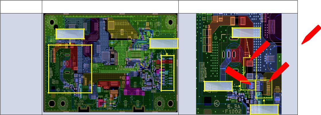
Troubleshooting
Board Name Board PWB (A side) |
Detail |
|
|
LD-XM-L |
|
|
|
CN1001 |
Detail |
F1002 |
|
F1002 |
|||
|
CN1001 |
||
D1001 |
|
||
|
|
||
Q1004 |
|
|
D1001 |
Q1004 |
Measuring
Point
13

Troubleshooting
Board Name Board PWB (A side) |
Detail |
|
|
LD-XM-L |
|
|
|
IC1002 |
|
|
|
C1042 |
Detail |
F1004 |
|
F1004 |
|||
|
IC1002 |
C1042 |
Measuring
Point
14

Troubleshooting
Board Name Board PWB (A side) |
Detail |
|
|
LD-XM-L |
|
|
F1003 |
|
|
C1024 |
|
|
IC1001 |
F1003 |
C1024 |
|
||
|
|
|
|
Detail |
|
IC1001 |
Measuring
Point
15
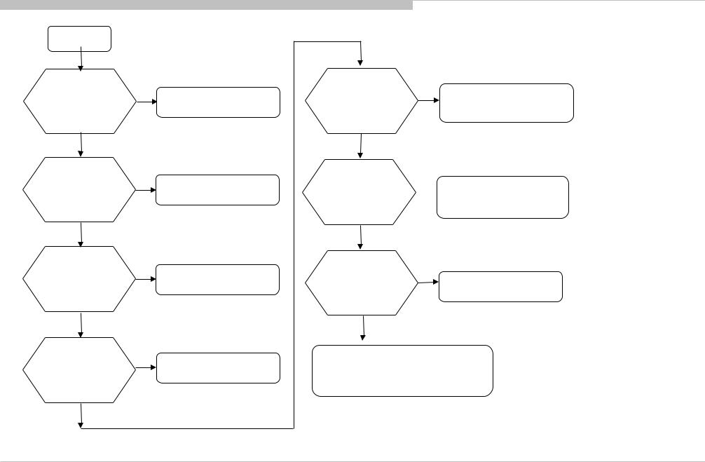
Troubleshooting
3-1-3. NO POWER: Ayu2L control
No Power
Check STBY_+3.3V
at AYU2L
(H15, H16, H17 pin C7376)
OK
Check STBY_+1.8V
at AYU2L
(H19 pin
C7374)
OK
Check STBY_+1.0V
at AYU2L
(J15, J16, J17 pin C7380)
OK
Check Xtal oscillation X7301, 32.768kHz (A23, B23 pin
R7396)
OK
NG
NG
NG
NG
look for where
STBY_+3.3V is NG.
look for where
STBY_+1.8V is NG.
look for where
STBY_+1.0V is NG.
Replace X7301 or Ayu2L
Check AC_MON |
NG |
Look for AC_MON line |
at AYU2 |
|
at CN9101 pin12/C9131 or |
(C11 pin C7334) |
|
Adapter/ G board failure |
OK |
|
|
Check MAIN_PWR
at AYU2
(C13 pin C7315)
OK
Check +19.5V(Adapter)
Or +12V(G-Board)
at CN9101 pin21
OK
NG Look for MAIN_POWER line  at CN9101 pin11
or replace AYU2
NG
Adapter/
G-board
It might be power supply problem Please refer "DC/DC converter check" sheet.
16

Troubleshooting |
|
|
|
|
|
Board |
Board PWB ( A side ) |
|
|
Detail |
|
Name |
|
|
|||
|
|
|
|
|
|
BAX-L |
|
|
1, 3, 4 |
C7376 |
2 |
|
|
|
|||
|
|
|
|
||
1. C7376 |
|
5,6 |
AYU2L |
|
C7374 |
|
|
|
|
||
2. C7374 |
1, 3, 4 |
2 |
C7380 |
|
|
|
|
||||
|
|
|
|||
3. C7380 |
|
|
|
|
|
4. R7396 |
|
|
|
|
|
5. C7334 |
|
|
|
|
X7301 |
|
|
|
|
|
|
6. C7315 |
|
|
|
R7396 |
|
|
|
5, 6 |
|
|
|
|
|
|
|
|
|
C7334
C7315
17
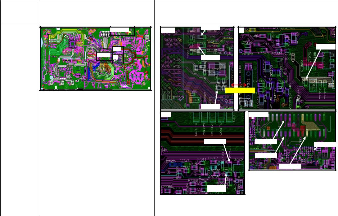
Troubleshooting |
|
|
|
|
|
|
Board |
Board PWB ( A side ) |
|
|
Detail |
|
|
Name |
|
|
|
|||
|
|
|
|
|
|
|
BAX-L |
|
7. CN9101 |
1, 3, 4 |
C7376 |
2 |
|
|
|
|
||||
|
|
|
|
|||
1. C7376 |
|
5,6 |
AYU2L |
|
|
C7374 |
|
|
|
|
|
||
2. C7374 |
1, 3, 4 |
2 |
C7380 |
|
|
|
|
|
|
||||
|
|
|
|
|||
3. C7380 |
|
|
|
|
|
|
4. R7396 |
|
|
|
|
|
|
5. C7334 |
|
|
|
|
X7301 |
|
|
|
|
|
|
|
|
6. C7315 |
|
|
|
R7396 |
|
|
|
|
5, 6 |
|
7. CN9101 |
|
|
|
|
|
|
|
||
7. CN9101 |
|
|
|
|
|
|
|
|
|
|
C7334 |
Pin12 |
C9131 |
|
|
|
|
|
|
|
|
|
|
|
|
Pin11 |
|
|
|
|
|
|
|
Pin21 |
|
|
|
|
C7315 |
|
|
18

Troubleshooting |
|
|
|
|
||
CONDITION |
SYMPTOM |
|||||
|
|
|||||
|
|
|
|
|||
|
|
19.5V_SS not available. |
Board will not turn ON. No blinking. |
|||
|
|
|
|
|
||
|
|
STBY_+3.3V, STBY_+1.8V and STBY_+1.0V not |
Board will not turn ON. No blinking. |
|||
|
3-1-4. NO POWER: DC/DC converter check |
available. |
||||
|
|
|
||||
|
|
|
|
|
||
|
|
|
|
|
||
|
|
|
19.5V_HOLD not available. |
2X blinking. |
|
|
|
|
|
|
|||
|
|
+5.0V_MAIN not available. |
2X blinking. |
|||
|
|
|
|
|
||
|
|
D+1.0V, +5.0V_VBUS, +3.3V_MAIN_1, |
3X blinking. |
|||
|
|
DDR3_+1.5V or +1.8V_MAIN not available. |
||||
|
|
|
|
|||
|
|
|
|
|
||
|
|
D+1.1V not available. |
Board turn ON. No blinking at first, but after |
|||
|
|
few minutes (±5min) 8X blinking occur. |
||||
|
|
|
|
|||
|
START |
|
|
|
|
|
|
|
|
|
|
||
IC9106 output or input short to GND?
C9302,
C9214
NO
IC9101 output or input short to GND? SL9104,
C9114
NO
Q9108 output or input short to GND? SL9110,
C9158
NO
YES |
|
|
YES |
|
|||||
Remove |
Other part in |
||||||||
|
|
|
|
|
|
+5.0V_VBUS line or |
|||
|
|
|
IC9106. |
|
|
|
|||
|
|
|
|
|
|
19.5V_SS line |
|||
|
|
|
Still short? |
|
|
|
|||
|
|
|
|
|
|
broken. |
|||
|
|
|
|
|
|
|
|
||
|
|
|
|
NO |
|
|
|
|
|
|
|
|
|
|
|
|
|
||
|
|
|
|
|
|
|
|
|
|
|
|
|
IC9106 broken |
|
|
|
|
||
YES |
|
|
YES |
|
|||||
|
|
|
|||||||
Remove |
Other part in |
||||||||
|
|
|
|
|
|
||||
|
|
|
|
|
|
+5.0V_MAIN line or |
|||
|
|
|
IC9101. |
|
|
|
|||
|
|
|
|
|
|
19.5V_SS line |
|||
|
|
|
Still short? |
|
|
|
|||
|
|
|
|
|
|
broken. |
|||
|
|
|
|
|
|
|
|
||
|
|
|
|
NO |
|
|
|
|
|
|
|
|
|
|
|
|
|
||
|
|
|
|
|
|
|
|
|
|
|
|
|
IC9101 broken |
|
|
|
|
||
YES |
|
|
YES |
|
|||||
|
|
|
|||||||
Remove |
Other part in D+1.0V |
||||||||
|
|
|
|
|
|
||||
|
|
|
|
|
|
line or +5.0V_MAIN |
|||
|
|
|
Q9108. Still |
|
|
|
|||
|
|
|
|
|
|
line broken. (AYU2L |
|||
|
|
|
short? |
|
|
|
|||
|
|
|
|
|
|
maybe broken) |
|||
|
|
|
|
|
|
|
|
||
|
|
|
|
NO |
|
|
|
|
|
|
|
|
|
|
|
|
|
||
|
|
|
|
|
|
|
|
||
|
|
|
|
|
|
|
|
|
|
|
|
|
Q9108 broken |
|
|
|
|
||
|
|
|
|
|
|
|
|
|
|
IC9103 output or input short to GND? SL9110,
C9147
NO
IC9104 output or input short to GND? SL9107, C9155
NO
IC9105 output or input short to GND? SL9108,
C9163
NO
SHEET 2
YES |
Remove |
|
YES |
Other part in D+1.0V |
||||||||
|
|
|
|
|
|
|
|
|
|
|||
|
|
|
|
|
|
|
|
|
|
line or +5.0V_MAIN |
||
|
|
|
|
|
IC9103. |
|
|
|
|
|
||
|
|
|
|
|
|
|
|
|
|
line broken. (AYU2L |
||
|
|
|
|
|
Still short? |
|
|
|
|
|
||
|
|
|
|
|
|
|
|
|
|
maybe broken) |
||
|
|
|
|
|
|
|
|
|
|
|
|
|
|
|
|
|
|
|
NO |
|
|
|
|
|
|
|
|
|
|
|
|
|
|
|
|
|
|
|
|
|
|
|
|
|
|
|
|
|
|
|
|
|
|
|
|
|
|
|
|
|
|
|
|
|
|
|
|
|
|
IC9103 broken |
|
|
|
|
|
|
|
|
|
|
|
|
|
|
|
|
|
|
|
|
|
YES |
|
|
YES |
|
|||||||
|
Remove |
Other part in |
||||||||||
|
|
|
|
|
|
|
|
|
|
|||
|
|
|
|
|
IC9104. |
|
|
|
|
|
+3.3V_MAIN_1 line |
|
|
|
|
|
|
Still |
|
|
|
|
|
or +5.0V_MAIN line |
|
|
|
|
|
|
short? |
|
|
|
|
|
broken. |
|
|
|
|
|
|
|
NO |
|
|
|
|
|
|
|
|
|
|
|
|
|
|
|
|
|
|
|
|
|
|
|
|
|
|
|
|
|
|
|
|
|
|
|
|
|
|
|
|
|
|
|
|
|
|
|
|
|
|
IC9104 broken |
|
|
|
|
|
|
|
YES |
|
|
|
YES |
|
|||||||
|
|
|
|
|||||||||
Remove |
|
Other part in D+1.1V |
||||||||||
|
|
|
|
|
|
|
|
|
|
|||
|
|
|
|
|
IC9105. |
|
|
|
|
|
line or +5.0V_MAIN |
|
|
|
|
|
|
|
|
|
|
|
|||
|
|
|
|
|
Still short? |
|
|
|
|
|
line broken. |
|
|
|
|
|
|
|
|
|
|
|
|
|
|
NO
IC9105 broken
19

Troubleshooting |
|
|
|
|
|
|
3-1-4. NO POWER: DC/DC converter check |
|
|
|
|
||
SHEET 2 |
|
|
|
|
|
|
|
|
|
|
|
Check fuse |
OPEN |
|
|
|
|
|
F9101, F9102, |
High current surge |
|
|
|
|
|
F9104, F9105, |
|
|
|
|
|
|
|
|
IC9104 |
YES |
|
YES |
Other part in |
F9106. |
|
output or |
|
|
|
|||
Remove |
+1.5V_DDR line or |
|
|
|||
input short |
|
|
|
|
||
|
IC9104. Still |
|
+5.0V_MAIN line |
OK |
|
|
to GND? |
|
|
|
|||
SL9109, |
|
short? |
|
broken. (DDR maybe |
|
|
|
|
|
broken) |
|
|
|
C9171 |
|
|
|
|
|
|
|
NO |
|
|
|
|
|
|
|
|
|
SHEET 3 |
|
|
NO |
|
|
|
|
|
|
|
IC9104 broken |
|
|
|
|
|
|
|
|
|
|
|
|
Q9107 |
YES |
|
YES |
|
|
|
output or |
Remove |
Other part in |
|
|
||
input short |
|
|
+3.3V_MAIN line or |
|
|
|
|
Q9107. Still |
|
|
|
||
to GND? |
|
|
+3.3V_MAIN_1 line |
|
|
|
|
short? |
|
|
|
||
SL9106, |
|
|
broken. |
|
|
|
|
|
|
|
|
||
C9148 |
|
NO |
|
|
|
|
|
|
|
|
|
|
|
NO |
|
Q9107 broken |
|
|
|
|
|
|
|
|
|
|
|
20
Troubleshooting
3-1-4. NO POWER: DC/DC converter check
Sheet 3 |
|
|
|
|
|
||
|
|
|
|
|
|
|
|
|
|
|
Turn ON board |
|
|
||
19.5V_SS, |
|
|
|||||
|
|
|
|
|
|
||
|
|
NO |
|
||||
|
|
||||||
19.5V_HOLD |
|
Check LD Board or |
|||||
|
|
|
|
||||
OK? |
|
|
|
|
Harness |
||
C9196, C9197 |
|
|
|
|
|
||
|
|
|
|
|
|||
|
YES |
|
|
|
|
|
|
|
|
|
|
|
|
||
STBY_+3.3V
OK?
L9107
YES
STBY_+1.8V, STBY_+1.0V OK? C7374,C736
9 YES
+5V_VBUS (IC9106) OK?
C9214
YES
+5V_MAIN (IC9101) OK?
SL9104
YES
NO |
Check LD Board or |
|
|
|
|
|
|
Harness |
|
|
|
NO |
Check IC7304 (1.8V) |
|
|
|
|
|
|
or IC7305 (1.0V) |
|
|
|
NO
IC9106 broken
MAIN_ YES PWR
high
NO |
NO |
|
|
IC9101 broken |
|
|
|
Refer AYU2L manual service sheet
D+1.0V
(IC9103) OK?
SL9110
 YES
YES
+3.3V_MAIN_1 (IC9104) OK?
SL9107
 YES
YES
D+1.1V
(IC9105) OK?
SL9108
YES
+1.8V_MAIN
OK?
C9202
 YES
YES
+1.5V_DDR (IC9104) OK?
SL9109
YES
+3.3V_MAIN
(Q9107) OK?
SL9106
YES
All
DDCON
OK
NO
NO |
SYSTE YES |
||
|
|
M1_P |
|
|
|
WR |
|
|
|
high |
|
NO
NO
Refer AYU2L manual service sheet
NO |
SYSTE |
YES |
|
M2_P |
|
|
WR |
|
|
high |
|
NO
Refer AYU2L NO manual service
sheet
SYSTE YES M3_P
WR high
NO
NO
Refer AYU2L manual service sheet
IC9103 broken
IC9104 broken
IC9105 broken
IC9201 broken
IC9104 broken
Q9107 broken
21

1
2
4
3
22

1
SL9110 |
|
F9101 |
19.5V_S |
L9107 |
|
S |
|
|
|
|
|
F9102 |
|
|
19.5V_HOL |
|
C9114 |
D |
|
C9302 |
|
MAIN_PW |
|
|
R |
IC9101 |
|
C9158 F9105 |
|
|
|
SL9104 |
|
Q9108 |
|
|
|
|
|
|
|
IC9106 |
C9147 |
|
|
IC9103 |
SYSTEM1_PWR
C9214
23
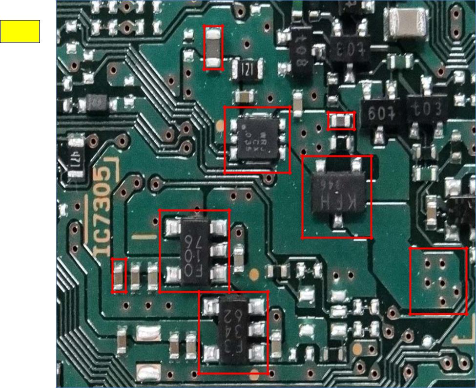
2
C9202
C9148
IC9201
Q9107
IC7305
C7369
SL9106
C7374 |
|
IC7304 |
|
||
|
|
|
|
|
|
24
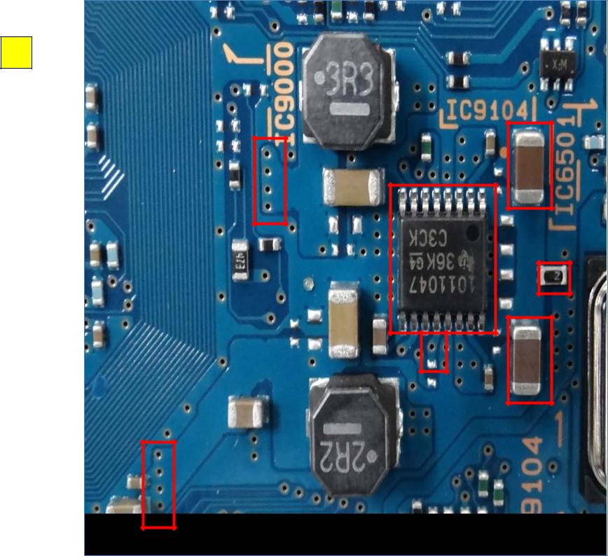
3
SL9107
IC9104
SYSTEM |
3_PWR |
SL9109
C9155 |
F9104
C9171 |
25

4
SL910
8
IC9105
C9163
F9106
26

Troubleshooting
3-1-5. NO POWER – AYU2L failure
AYU2L Fail Suspected
eMMC / RawNAND erase
Product SW rewrite |
|
|
|
Yes |
Product SW |
Recover? |
|
|
|
writing issue |
|
|
|
|
No |
|
|
AYU2L LOG is |
Yes |
Check DDR |
|
||
displayed |
|
using CheckSW |
No
(1) Check DDR & |
Yes |
|
Replace |
||
eMMc / RawNAND |
||
AYU2L or Board |
||
interface OK? |
||
|
No
Replace Board
Find Some |
No |
Check |
|
||
|
eMMC / RawNAND |
|
Error message |
|
|
|
using CheckSW |
|
|
|
|
Yes |
|
No |
DDR device fail |
|
eMMC/ RawNAND |
|
data fail |
|
|
|
|
From the error |
|
Data fails are |
message, we can |
|
especially in |
find which device |
|
environment area. |
has failure. |
|
If this Area has |
Move to device |
|
broken, check soft |
analysis phase. |
|
cannot run |
Yes
Find Some Error message
No
Store SW log, Check SW behaviors.
Erase
eMMC/ RawNAND
In this case, corrupted data are written to eMMC/ NAND flash in proper way.
So, we have to check the logs of exception or errors.
Erase eMMC/ RawNAND is a last option. If still NG after erase, please replace eMMC/RawNAND
Check error message It is unacceptable error?
Yes
Erase & Replace
eMMC/ RawNAND
Product SW write
If still NG after SW rewrite, please go to
(1) Check MMC/RawNAND interface
27

Troubleshooting
3-1-6. NO POWER – AYU2L replacement
AYU2L replacement flow
eMMC / RawNAND erase
AYU2L replacement
Product SW write
No
Recover?
Yes
AYU2L issue
Data on eMMC/NAND need to be erase first before changing AYU2L.
Board Issue
28
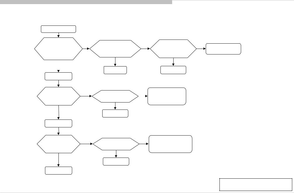
Troubleshooting
3-2. LED BLINKING
3-2-1. LED Blinking: 2x (Main power Error)
BAX-L board (XM-L)
2-time blinking
Check 19.5V_HOLD at pin 18 of CN9101 on B* Board
OK 
Turn off power
IC9101 output
or input short to GND? SL9104, C9114
OK
Turn on power
+5V_MAIN (IC9101) OK? SL9104
OK
B* Board
NG
NG
NG
Check |
NG |
Replace |
NG |
|
|
Harness/connection |
AC Adapter |
||||
|
LD* Board |
|
|||
LD*Board to B*Board |
|
|
|
||
|
|
|
|
||
OK |
|
OK |
|
|
|
Harness |
|
LD* Board |
|
|
Remove IC9101.
Still short? OK
IC9101 broken
NG |
Other part in |
|
+5.0V_MAIN line or |
||
|
||
|
||
|
19.5V_SS line broken. |
NG |
Refer AYU2L |
MAIN_PWR high? |
Troubleshooting |
|
|
OK |
|
IC9101 broken |
|
Note: Board Details refer Section 3 main page.
29
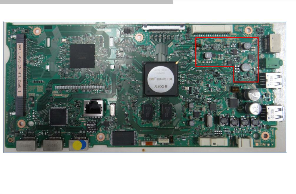
Troubleshooting
3-2-1. LED Blinking: 2x (Main power Error)
Troubleshooting References
1
30
Loading...