


 Loading...
2-599-864-12(1)
LCD Digital Color TV
Operating Instructions
KDL-V26XBR1
KDL-V32XBR1
KDL-V40XBR1
© 2005 Sony Corporation

Owner’s Record
The model and serial numbers are located at the rear of the LCD TV, below the Sony logo, on the sticker, and also on the TV box (white label). Record these numbers in the spaces provided below. Refer to them whenever you call upon your Sony dealer regarding this product.
Model No.
Serial No.
Contacting Sony
If, after reading the following instructions, you have additional questions related to the use of your Sony® TV, Please call one of the following numbers.
Customers in the continental United States contact the Direct Response Center at:
1-800-222-SONY (7669)
Customers in Canada contact the Customer Relations Center at:
1-877-899-SONY (7669)
2

WARNING
To reduce the risk of fire or electric shock, do not expose this apparatus to rain or moisture.
CAUTION |
RISK OF ELECTRIC SHOCK |
DO NOT OPEN |
ATTENTION |
RISQUE DE CHOC ELECTRIQUE, |
NE PAS OUVRIR |
PRECAUCION |
RIESGO DE CHOQUE ELECTRICO |
NO ABRIR |
This symbol is intended to alert the user to the presence of uninsulated “dangerous voltage” within the product’s enclosure that may be of sufficient magnitude to constitute a risk of electric shock to persons.
This symbol is intended to alert the user to the presence of important operating and maintenance (servicing)
instructions in the literature accompanying the appliance.
The apparatus shall not be exposed to dripping or splashing and no objects filled with liquids, such as vases, shall be placed on the apparatus.
CAUTION
To prevent electric shock, do not use this polarized AC plug with an extension cord, receptacle or other outlet unless the blades can be fully inserted to prevent blade exposure.
Note on Caption Vision
This TV provides display of TV closed captioning in accordance with §15.119 of the FCC rules.
For Customers in the United
States
If you have any questions about this product, you may call; Sony Customer Information Services Center 1-800-222-7669 or http://www.sony.com/
Declaration of Conformity
Trade Name: SONY
Model: KDL-V26XBR1/KDL-V32XBR1/
KDL-V40XBR1
Responsible Party: Sony Electronics Inc.
Address: 16450 W. Bernardo Dr,
San Diego, CA 92127 U.S.A.
Telephone Number: 858-942-2230
This device complies with part 15 of the FCC rules. Operation is subject to the following two conditions: (1) This device may not cause harmful interference, and (2) this device must accept any interference received, including interference that may cause undesired operation.
NOTIFICATION
This equipment has been tested and found to comply with the limits for a Class B digital device, pursuant to Part 15 of the FCC Rules. These limits are designed to provide reasonable protection against harmful interference in a residential installation. This equipment generates, uses and can radiate radio frequency energy and, if not installed and used in accordance with the instructions, may cause harmful interference to radio communications. However, there is no guarantee that interference will not occur in a particular installation. If this equipment does cause harmful interference to radio or television reception, which can be determined by turning the equipment off and on, the user is encouraged to try to correct the interference by one or more of the following measures:
sReorient or relocate the receiving antenna.
sIncrease the separation between the equipment and receiver.
sConnect the equipment into an outlet on a circuit different from that to which the receiver is connected.
sConsult the dealer or an experienced radio/TV technician for help.
You are cautioned that any changes or modifications not expressly approved in this manual could void your authority to operate this equipment.
For Customers in Canada
This Class B digital apparatus complies with Canadian ICES-003.
Safety
sOperate the TV only on 120-240 V AC.
sUse the AC power cord specified by Sony and suitable for the voltage where you use it.
sThe plug is designed, for safety purposes, to fit into the wall outlet only one way. If you are unable to insert the plug fully into the outlet, contact your dealer.
sIf any liquid or solid object should fall inside the cabinet, unplug the TV immediately and have it checked by qualified service personnel before operating it further.
sIf you will not be using the TV for several days, disconnect the power by pulling the plug itself. Never pull on the cord.
sFor details concerning safety precautions, see “Important Safety Instructions” on page 4 and “Important Safeguards” on page 5.
Installing
sThe TV should be installed near an easily accessible power outlet.
sTo prevent internal heat buildup, do not block the ventilation openings.
sDo not install the TV in a hot or humid place, or in a place subject to excessive dust or mechanical vibration.
sAvoid operating the TV at temperatures below 41°F (5°C).
sIf the TV is transported directly from a cold to a warm location, or if the room temperature changes suddenly, the picture may be blurred or show poor color due to moisture condensation. In this case, please wait a few hours to let the moisture evaporate before turning on the TV.
sTo obtain the best picture, do not expose the screen to direct illumination or direct sunlight. It is recommended to use spot lighting directed down from the ceiling or to cover the windows that face the screen with opaque drapery. It is desirable to install the TV in a room where the floor and walls are not of a reflective material.
CAUTION
Use the following Sony appliance(s) only with the following WALL-MOUNT BRACKET.
Use with other WALL-MOUNT BRACKET may cause instability and possibly result in injury.
SONY APPLIANCE MODEL NO.
KDL-V26XBR1
KDL-V32XBR1
KDL-V40XBR1
SONY WALL-MOUNT BRACKET MODEL NO.
SU-WL31 (KDL-V26XBR1/KDL-V32XBR1)
SU-PW2 (KDL-V40XBR1)
To Customers
Sufficient expertise is required for installing the specified product. Be sure to subcontract the installation to Sony dealers or licensed contractors and pay adequate attention to safety during the installation.
(Continued)
3

For Customers in the United States
This product contains mercury. Disposal of this product may be regulated if sold in the United States. For disposal or recycling information, please contact your local authorities or the Electronics Industries Alliance (http://www.eiae.org).
To Sony Dealers
For installation of SONY WALL-MOUNT BRACKET, be sure to read and follow the instructions supplied with those optional products.
Note
This digital television is capable of receiving analog basic, digital basic and digital premium cable television programming by direct connection to a cable system providing such programming. A security card provided by your cable operator is required to view encrypted digital programming. Certain advanced and interactive digital cable services such as video-on-demand, a cable operator’s enhanced program guide and data-enhanced television services may require the use of a set-top box. For more information call your local cable operator.
This television also includes a QAM demodulator which should allow you to receive unscrambled digital cable television programming via subscription service to a cable service provider. Availability of digital cable television programming in your area depends on the type of programming and signal provided by your cable service provider.
Trademark Information
CableCARD™ is a trademark of Ca ble Television Laboratories, Inc.
TruSurround XT, SRS 3D Mono and the 
 symbol are trademarks of SRS Labs, Inc. TruSurround XT and SRS 3D Mono technologies are incorporated under license from SRS Labs, Inc.
Licensed by BBE Sound, Inc. under USP4638258, 4482866. “BBE” and BBE symbol are trademarks of BBE Sound, Inc.
Macintosh is a trademark licensed to Apple Computer, Inc., registered in the U.S.A and other countries.
WEGA, WEGA GATE, Steady Sound, Digital Reality Creation and CineMotion are registered trademarks of Sony Corporation.
“PlayStation” is a trademark of Sony Computer Entertainment, Inc.
Manufactured under license from Dolby Laboratories. “Dolby” and the double-D symbol are trademarks of Dolby Laboratories.
This TV incorporates High-Definition Multimedia Interface (HDMI™) technology.
HDMI, the HDMI logo and High-Definition Multimedia Interface are trademarks or registered trademarks of HDMI Licensing LLC.
Important Safety Instructions
1)Read these instructions.
2)Keep these instructions.
3)Heed all warnings.
4)Follow all instructions.
5)Do not use this apparatus near water.
6)Clean only with dry cloth.
7)Do not block any ventilation openings. Install in
accordance with the manufacturer’s instructions. 8) Do not install near any heat sources 


such as radiators, heat registers, stoves, or other apparatus (including amplifiers) that produce heat.
9)Do not defeat the safety purpose of the polarized or grounding-type plug. A polarized plug has two blades with one wider than the other. A grounding type plug has two blades and a third grounding prong. The wide blade or the third prong are provided for your safety. If the provided plug does not fit into your outlet, consult an electrician for replacement of the obsolete outlet.
10)Protect the power cord from being walked on or pinched particularly at plugs, convenience receptacles, and the point where they exit from the apparatus.
11)Only use attachments/accessories specified by the manufacturer.
12)Use only with the cart, stand, tripod, bracket, or table specified by the manufacturer, or sold with the apparatus. When a cart is used, use caution when moving the cart/apparatus combination to avoid injury from tip-over.
13)Unplug this apparatus during lightning storms or when unused for long periods of time.
14)Refer all servicing to qualified service personnel. Servicing is required when the apparatus has been damaged in any way, such as power-supply cord or plug is damaged, liquid has been spilled or objects have fallen into the apparatus, the apparatus has been exposed to rain or moisture, does not operate normally, or has been dropped.
4

Important
Safeguards
Before using your TV, please read these instructions completely, and keep this manual for future reference.
Carefully observe and comply with all warnings, cautions and instructions placed on the unit or described in the operating instructions or service manual.
WARNING
To guard against injury, the following basic safety precautions should be observed in the installation, use and servicing of the unit.
Use
Power Sources
This unit should be operated only from the type of
power source indicated on the information label. 120~240V AC If you are not sure of the type of electrical power
supplied to your home, consult your dealer or local power company.
Grounding or Polarization
This unit is equipped with a polarized AC power cord plug (a plug having one blade wider than the other), or with a three-wire grounding type plug (a plug having a third pin for grounding). Follow the instructions below:
For the unit with a three-wire grounding type AC power cord plug (Class 1 unit)
This unit must be connected to an AC power socket outlet with a protective earthing connection.
For the unit with a polarized AC power cord plug
This plug will fit into the power outlet only one way. This is a safety feature. If you are unable to insert the plug fully into the outlet, try reversing the plug.
If the plug still fails to fit, contact your electrician to have a suitable outlet installed. Do not defeat the safety purpose of the polarized plug by forcing it in.
Wall outlet
Do not use a poor fitting outlet.
Insert the plug fully into the outlet. If it is loose, it may cause arcing and result in fire.
Contact your electrician to have the outlet changed.
Wiring
For your safety, unplug the AC power cord when wiring cables.
Electric shock
Do not touch the AC power cord or the unit with a wet hand. If you plug/unplug the AC power cord from the unit with a wet hand, it may cause electric shock.
Cleaning
sClean the AC power plug regularly.
If the plug is covered with dust and it picks up moisture, its insulation may deteriorate and result in fire. Unplug the AC power plug and clean it regularly.
sUnplug the AC power cord when
cleaning this unit. If not, it may result in electric shock.
s Clean the cabinet of the TV with a dry
soft cloth. To remove dust from the screen, wipe it gently with a soft cloth.
Stubborn stains may be removed with
a cloth slightly dampened with a solution of mild soap and warm water. Never use strong solvents such as thinner or benzine for cleaning.
sIf using a chemically pretreated cloth, please follow the instruction provided on the package.
sIf the picture becomes dark after using the TV for a long period of time, it may be necessary to clean the inside of the TV. Consult qualified service personnel.
Overloading
Do not overload wall outlets, extension cords or convenience receptacles beyond their capacity, since this can result in fire or electric shock.
Power
Always turn the unit off when it is not being used. When the unit is left unattended and unused for long periods of time, unplug it from the wall outlet as a precaution against the possibility of an internal malfunction that could create a fire hazard.
Sound
If a snapping or popping sound from the TV is continuous or frequent while the TV is operating, unplug the TV and consult your dealer or service technician. It is normal for TV’s to make occasional snapping or popping sounds, particularly when being turned on or off.
AC Power Cord
If you damage the AC power cord, it may result in fire or electric shock.
sDo not pinch, bend, or twist the cord excessively. The core lines may be bared and cut, and cause short-circuit, resulting in fire or electric shock.
sDo not convert or damage the AC power cord.
sDo not put anything heavy on the AC power cord. Do not pull the AC power cord.
sKeep the AC power cord away from heat sources.
sBe sure to grasp the plug when disconnecting the AC power cord. If the AC power cord is damaged, stop using it and ask your dealer or Sony service center to exchange it.
Batteries
Do not dispose of batteries in a fire.
Do not short circuit, disassemble or overheat the batteries.
Disposal of used batteries
To preserve our environment, dispose of used batteries according to your local laws or regulations.
Ventilation holes
Never push objects of any kind into the unit through the cabinet slots as they may touch dangerous voltage points or short out parts that could result in a fire or electric shock. Never spill liquid of any kind on the unit.
Objects and Liquid Entry
Do not place any objects on the unit.
The apparatus shall not be exposed to dripping or splashing and no objects filled with liquids, such as vases, shall be placed on the apparatus.
(Continued)
5

Attachments
Do not use attachments not recommended by the manufacturer, as they may cause hazards.
Medical institution
Do not place this unit in a place where medical equipment is in use.
It may cause malfunction of medical instruments.
Moisture and flammable objects
sDo not use plugged sets near water — for
example, near a bathtub, washbowl, kitchen sink, or laundry tub, in a wet basement, or near a swimming pool, etc. It may result in fire or electric shock.
sDo not let this unit get wet. Never spill liquid
of any kind on the unit. If any liquid or solid object does fall through, do not operate the unit. It may result in electric shock or damage to the unit. Have it checked immediately by qualified personnel.
sTo prevent fire, keep flammable objects or open flame (e.g. candles) away from the unit.
Accessories
Do not place the unit on an unstable cart, stand, table or shelf. The unit may fall, causing serious injury to a child or an adult and serious damage to the unit. No part of the TV should overhang any edge of the TV cart or stand; any overhanging edge is a safety hazard. An appliance and cart combination should be moved with care. Quick stops, excessive force, and uneven surfaces may cause the appliance and cart combination to overturn.
Broken pieces
Do not throw anything at the unit.
The screen glass may break by the impact and cause serious injury.
Cable wiring
Take care not to catch your feet on the cables. It may damage the unit.
Heat
Do not touch the surface of the TV.
It remains hot, even for some time after the TV is turned off.
Volume adjustment
sAdjust the volume so as not to trouble your neighbors. Sound carries very easily at night time. Therefore, closing the windows or using headphones is suggested.
sWhen using headphones, adjust the volume so as to avoid excessive levels, as hearing damage may result.
Disposal of the TV
sDo not dispose the TV with general household waste.
sThe LCD contains a small amount of liquid crystal. The fluorescent tube used in this display contains mercury. Follow your local ordinances and regulations for disposal.
Handling of broken glass and liquid crystal leakage
If the LCD panel gets damaged, crystalline liquid leakage may occur, or scattered broken glass may result. Do not touch broken glass or crystalline liquid (which is toxic), with bare hands as cuts or poisoning/ skin irritation may occur. Also, do not let glass fragments or leaked crystalline liquid get into your eyes or mouth. Should either contact your eyes or mouth, rinse the contacted area thoroughly with water and consult your doctor.
LCD screen
sAlthough the LCD screen is made with high-precision technology and has effective pixels of 99.99% or more, black dots may appear or bright points of light (red, blue, or green) may appear constantly on the LCD screen. This is a structural property of the LCD panel and is not a malfunction.
sDo not expose the LCD screen surface to the sun. Doing so may damage the screen surface.
sDo not push or scratch the LCD screen, or place objects on top of the TV. The image may be uneven or the LCD panel may be damaged.
sIf the TV is used in a cold place, a smear may occur in the picture or the picture may become dark. This does not indicate a failure. These phenomena improve as the temperature rises.
sGhosting may occur when still pictures are displayed continuously. It may disappear after a few moments.
sThe screen and cabinet get warm when the TV is in use. This is not a malfunction.
sAvoid spraying insect repellent with volatile material to the screen.
sAvoid prolonged contact with rubber or plastic made material.
Fluorescent lamp
This TV uses a special fluorescent lamp as its light source. If the screen image becomes dark, flickers, or does not appear, the fluorescent lamp has run down and should be replaced. For replacement, consult qualified service personnel.
Installation and moving
Carry the TV in the specified manner
Carrying the TV requires at least two people.
If you carry the TV in a manner other than that specified and without the specified number of persons, it may drop and a serious injury may result. Be sure to follow the instructions given below.
sCarry the TV with the specified number of
persons.
s Carry the TV holding the upper and bottom frames of the TV as illustrated.
sHold the TV securely when carrying it.
sAs the glass surface of the TV has a special
coating, be careful to avoid touching the glass surface as far as possible.
sWhen transporting, do not subject the unit to shocks or vibration, or excessive force.
Installation
sWhen installing or removing the TV
on the wall, be sure to use qualified contractors. Wall mount installation requires the use of a wall-mount bracket. If the TV is installed or
removed from the wall by a person other than a qualified contractor, the
unit may fall and cause serious injury if the unit is not installed securely.
sTo prevent injury, this apparatus must be securely attached to the stand/wall in accordance with the installation instructions.
6

Placement for viewing
It is recommended to watch the TV at a distance of 3 to 7 times that of the screen height, and in moderate brightness. Watching the TV for too long or in a dark room will cause eye fatigue.
Optional accessories
Observe the following when installing the TV using a wall-mount bracket. If the TV is not secured properly, it may fall and cause injury.
sBe sure to follow the operating instructions supplied with the wall-mount bracket when
installing the unit.
sBe sure to attach the brackets supplied with the wall-mount bracket.
Protruding location
Do not install the TV in protruding locations. If you install the unit in the following locations, injury may result.
sDo not install the unit in a location where the unit protrudes, such as pillars.
sDo not install the unit in a location that may cause injury.
Oils
Do not install this unit in restaurants where oily vapors occur. Dust absorbing oil may enter into the unit and damage the unit.
Corrosion
Use of this TV near the seashore may subject the set to excessive salt, corrosion and internal damage and result in deterioration of the TV’s performance. If the set will be subjected to these conditions, steps should be taken to reduce the humidity and temperature of the area where the TV is located.
Ventilation
The slots and openings in the TV are provided for necessary ventilation. To ensure reliable operation of the unit, and to protect it from overheating, these slots and openings must never be blocked or covered.
Unless proper ventilation is provided, the unit may gather dust and get dirty. For proper ventilation, observe the following:
sDo not install the unit turned backward or sideways.
s Do not install the unit turned over or upside down.
s Never cover the slots and openings with a cloth or other materials.
s Never block the slots and openings by placing the unit on a bed, sofa, rug or other similar surface.
s Never place the unit in a confined space, such as a bookcase or built-in cabinet, unless proper ventilation is provided.
sLeave some space around the unit. Otherwise, adequate air-circulation may be blocked causing overheating and cause fire or damage the unit.
When installing the unit on the wall, allow this much space.
30 cm
(117/8 inches)
10 cm |
10 cm |
(4 inches) |
(4 inches) |
 10 cm (4 inches)
When installing the unit using a stand, allow this much space.
30 cm
(117/8 inches)
10 cm |
10 cm |
15 cm |
(4 inches) |
(4 inches) |
(6 inches) |
Never install the unit as follows: |
|
Air circulation is blocked. |
Air circulation is blocked. |
Outdoor use
Do not install this unit outdoors. If the unit is exposed to rain, it may result in fire or electric shock. If the unit is exposed to direct sunlight, the unit may heat up and cause damage to the unit.
Vehicle and ceiling
Do not install this unit in a vehicle or hang from the ceiling.
Bumping of the vehicle may cause the unit to fall down and cause injury.
Ship and vessel
Do not install this unit in a ship or vessel. If the unit is exposed to seawater, it may cause fire or damage the unit.
(Continued)
7

Preventing the TV from toppling over
Take measures to prevent the unit from toppling over and causing injury. To prevent the unit from toppling over, secure the unit to the wall or pillar.
Installing on a level surface
If you install the unit on a non-level surface, the unit may fall or drop and cause injury or damage.
Placing on a stable surface
If you place the unit on an unstable surface, the unit may fall and cause injury or damage.
Fall
Do not hang anything on the unit.
The unit may fall from the stand or wall-mount bracket, causing damage or serious injury.
AC power cord
Unplug the AC power cord when moving the unit. Do not move the unit with the AC power cord plugged in. It may damage the AC power cord and result in fire or electric shock.  Do not allow anything to rest on or roll over the power cord, and do not place the unit where the power cord is subject to wear or abuse.
Antennas
Outdoor Antenna Grounding
If an outdoor antenna is installed, follow the precautions below. An outdoor antenna system should not be located in the vicinity of overhead power lines or other electric light or power circuits, or where it can come in contact with such power lines or circuits.
WHEN INSTALLING AN OUTDOOR ANTENNA SYSTEM, EXTREME CARE SHOULD BE TAKEN TO KEEP FROM CONTACTING SUCH POWER LINES OR CIRCUITS AS CONTACT WITH THEM IS ALMOST INVARIABLY FATAL.
Be sure the antenna system is grounded so as to provide some protection against voltage surges and built-up static charges.
Section 810 of the National Electrical Code (NEC) in USA and Section 54 of the Canadian Electrical Code in Canada provides information with respect to proper grounding of the mast and supporting structure, grounding of the lead-in wire to an antenna discharge unit, size of grounding conductors, location of antenna discharge unit, connection to grounding electrodes, and requirements for the grounding electrode.
Antenna Grounding According to the National Electrical Code, ANSI/NFPA 70
|
Antenna lead-in wire |
|
Ground clamps |
|
|
|
Antenna discharge unit |
|
Electric service |
(NEC Section 810-20) |
|
Grounding conductors |
||
equipment |
||
|
(NEC Section 810-21) |
|
|
Ground clamps |
|
|
Power service grounding |
|
|
electrode system |
|
NEC: National Electrical Code |
(NEC Art 250 Part H) |
|
|
Lightning
For added protection for this TV during a lightning storm, or when it is left unattended and unused for long periods of time, unplug it from the wall outlet and disconnect the antenna. This will prevent damage to the receiver due to lightning and power-line surges.
Service
Damage Requiring Service
Do not attempt to service the set by yourself since opening the cabinet may expose you to dangerous voltage or other hazards.
Unplug the set from the wall outlet and refer servicing to qualified service personnel.
Replacement parts
When replacement parts are required, be sure the service technician certifies in writing that he/she has used replacement parts specified by the manufacturer that have the same characteristics as the original parts.
Unauthorized substitutions may result in fire, electric shock or other hazards.
Safety check
Upon completion of any service or repairs to the unit, ask the service technician to perform routine safety checks (as specified by the manufacturer) to determine that the unit is in safe operating condition, and to so certify. Ask a qualified service technician to dispose of the unit.
8

Contents
Introducing the TV |
|
Welcome .............................................................. |
11 |
Package Contents.......................................... |
11 |
Features......................................................... |
11 |
Installing the TV .................................................. |
13 |
Preventing the TV from Toppling Over .......... |
13 |
Bundling the Connecting Cables.................... |
14 |
Adjusting the Viewing Angle of the TV........... |
14 |
TV Controls and Connectors ............................. |
15 |
Front Panel .................................................... |
15 |
Side Panel...................................................... |
16 |
Rear Panel ..................................................... |
17 |
Connecting the TV |
|
Overview.............................................................. |
19 |
Making Video and Audio Connections ........... |
19 |
About Using S VIDEO.................................... |
20 |
About Using HDMI to DVI Adapter................. |
20 |
Basic Connections ............................................. |
21 |
Cable System or VHF/UHF............................ |
21 |
Cable Box and Antenna ................................. |
22 |
Cable Box ...................................................... |
23 |
Satellite Receiver ........................................... |
24 |
Digital Cable Box or Digital Satellite |
|
Receiver......................................................... |
25 |
Equipment with HDMI Connection ................. |
26 |
Equipment with DVI Connection .................... |
27 |
Equipment with Digital Audio (OPTICAL) ...... |
28 |
Using CableCARD Device .................................. |
29 |
About Using CableCARD Device................... |
29 |
Activating CableCARD Service...................... |
29 |
Removing the CableCARD Device ................ |
30 |
Setting Up the Channel List............................... |
31 |
Using Initial Setup .......................................... |
31 |
Connecting Optional Equipment....................... |
32 |
VCR and Cable .............................................. |
33 |
VCR and Cable Box....................................... |
34 |
Two VCRs for Tape Editing ........................... |
36 |
DVD Player with Component Video |
|
Connectors..................................................... |
37 |
DVD Player with S VIDEO and Audio |
|
Connectors ..................................................... |
38 |
Personal Computer ........................................ |
39 |
Camcorder or “PlayStation”............................ |
40 |
Audio Receiver ............................................... |
40 |
Watching the TV |
|
Overview .............................................................. |
41 |
Inserting Batteries into the Remote Control..... |
41 |
Button Descriptions............................................ |
42 |
Programming the Remote Control .................... |
44 |
Using Other Equipment with Your Remote |
|
Control........................................................... |
46 |
Special Buttons on the Remote Control ........... |
48 |
Using the GUIDE Button ................................ |
48 |
Using the WIDE Button .................................. |
50 |
Using the JUMP Button .................................. |
51 |
Using the FREEZE Button.............................. |
51 |
Using the POWER SAVING Button................ |
51 |
Introducing WEGA GATE |
|
Overview of WEGA GATE................................... |
52 |
Navigating and Selecting Items ......................... |
54 |
Using Favorites in WEGA GATE........................ |
54 |
Using Cable in WEGA GATE .............................. |
55 |
Using Antenna in WEGA GATE ......................... |
55 |
Using External Inputs in WEGA GATE.............. |
56 |
Using Photo in WEGA GATE.............................. |
56 |
Using Video in WEGA GATE .............................. |
56 |
Using Settings in WEGA GATE.......................... |
56 |
(Continued)
9

Using the Photo/Video Viewer |
|
About USB........................................................... |
57 |
Features......................................................... |
57 |
Connecting the USB Cable ............................ |
58 |
File Compatibility............................................ |
58 |
Using the Photo/Video Viewer Index ................ |
59 |
Using the Photo/Video Viewer Index ............. |
60 |
Viewing Photos ................................................... |
61 |
Photo Controls ............................................... |
61 |
Photo Menu Bar Options................................ |
62 |
Using Zoom and Pan ..................................... |
63 |
Using Rotate .................................................. |
63 |
Playing Movies.................................................... |
64 |
Movie Controls ............................................... |
64 |
Movie Menu Bar Options ............................... |
65 |
Photo/Video Viewer Index Menu Bar |
|
Options ......................................................... |
66 |
Slide Show Menu Options.............................. |
66 |
Contents Menu Options ................................. |
67 |
USB Media Menu........................................... |
67 |
Notes on Using USB Media................................ |
68 |
About DCF File Names .................................. |
68 |
Using the Settings |
|
Overview.............................................................. |
69 |
Accessing the Video Settings ........................... |
71 |
Selecting Video Options................................. |
71 |
Selecting PC Video Options........................... |
73 |
Accessing the Audio Settings ........................... |
74 |
Selecting Audio Options................................. |
74 |
Selecting PC Audio Options........................... |
76 |
Accessing the Screen Settings ......................... |
77 |
Selecting Screen Options .............................. |
77 |
Selecting PC Screen Options ........................ |
79 |
Accessing the Channel Settings ....................... |
80 |
Selecting Channel Options ............................ |
80 |
Accessing the Parental Lock Settings.............. |
82 |
Selecting Parental Lock Options.................... |
82 |
Viewing Blocked Programs ............................ |
83 |
Selecting Custom Rating Options .................. |
83 |
Accessing the Setup Settings ........................... |
85 |
Selecting Setup Options ................................ |
85 |
Programming Caption Vision ......................... |
87 |
Selecting PC Setup Options .......................... |
88 |
Accessing the Applications Settings................ |
90 |
Selecting Applications Options ...................... |
90 |
10
Other Information |
|
Overview .............................................................. |
92 |
Contacting Sony.................................................. |
92 |
Troubleshooting.................................................. |
92 |
Remote Control .............................................. |
92 |
CableCARD Device........................................ |
93 |
Video .............................................................. |
93 |
Audio .............................................................. |
94 |
Channels ........................................................ |
95 |
USB ................................................................ |
95 |
General........................................................... |
97 |
Specifications...................................................... |
98 |
Index..................................................................... |
99 |
Introducing the TV
Welcome
Thank you for purchasing this Sony LCD digital TV. This manual is for models KDL-V26XBR1, KDL-V32XBR1 and KDL-V40XBR1.
Package Contents Along with your new TV, the packing box contains a remote control, and two AA (R6) batteries. See page 98 for the complete list of packaging contents.
TV the Introducing
Features |
Some of the features that you will enjoy with your new TV include: |
|
s WEGA GATE™: WEGA GATE is a new feature that allows you to |
|
easily navigate to the most convenient TV functions: favorite channels, |
|
cable channels, antenna channels, external input list, viewing photo and |
|
movies or settings. |
|
s WEGA Engine: Delivers superb picture quality from any video source |
|
by minimizing the signal deterioration caused by digital-to-analog |
|
conversion and stabilizing the signal processing. This engine features |
|
unique Sony technology, including: |
|
• The first step in the digital processing system, Composite |
|
Component Processor (CCP-X), which enhances input signal-to- |
|
noise ratio by chroma decoder digital processing. |
|
• DRC® (Digital Reality Creation)-MF V1: Unlike conventional |
|
line doublers, the DRC Multifunction feature replaces the signal’s |
|
NTSC waveform with the near-HD equivalent by digital mapping |
|
processing. The DRC Palette option lets you customize the level of |
|
detail (Reality) and smoothness (Clarity) to create up to three |
|
custom palettes. |
|
s Integrated HDTV: You can watch digital television programs and |
|
enjoy the improved audio/video quality offered by these programs. |
|
s Wide Screen Mode: Watch conventional 4:3 aspect ratio broadcasts in |
|
wide screen (16:9) mode. |
|
s S-master Full Digital Amplifier: Delivers superb clear dialog and |
|
reproduces the original sound quality while minimizing any sound |
|
fragmentation or jitter noise. |
|
s CineMotion® : Using the reverse 3-2 pull down technology, the |
|
CineMotion feature provides smoother picture movement when playing |
|
back movies or other video sources on film. |
|
s Parental Control: V-Chip technology allows parents to block |
|
unsuitable programming from younger viewers. |
|
(Continued) |
11

Introducing the TV
sCableCARD™ slot: Provides cable subscribers with access to digitally encrypted cable channels — without the need for a set-top box — that will enable you to receive not only standard definition but also high definition television. The CableCARD device, which is provided by your cable TV company, is inserted into the TV’s rear panel CableCARD slot. After the service is activated with your cable TV company, the card replaces the need for a separate set-top box. (Check with your cable TV company about CableCARD service details, limitations, pricing, and availability. For more information about CableCARD device in this manual, see page 29.)
sComponent Video Input: Offers the best video quality for DVD (480p and 480i), and digital set-top box (1080i, 720p, 480p and 480i) connections.
sFavorite Channels: With the WEGA GATE function, allows you to navigate a list of up to 16 favorite channels without leaving the current channel.
sSteady Sound® : Equalizes volume levels so there is consistent output between programs and commercials.
sHDMI (High-Definition Multimedia Interface): Provides an uncompressed, all-digital audio/video interface between this TV and any HDMI-equipped audio/video component, such as a set-top box, DVD player, and A/V receiver. HDMI supports enhanced, or highdefinition video, plus two-channel digital audio.
sLight Sensor: Allows the picture brightness level to be optimized to ambient light. The effect from the Light Sensor depends on the setting of Picture Mode and Power Saving. The factory setting is Off.
sCaption Vision/ Info Banner: Allows Closed Caption and/or Channel Programming Information to be displayed.
12

Installing the TV
Preventing the TV |
Attaching the Support Belt |
from Toppling Over |
|
Introducing the TV
TV the Introducing
1Screw the support belt (supplied) to the TV stand with a wood screw (supplied).
2Attach the support belt to the stand, and screw the belt with a securing screw (supplied) using a coin, etc.
3Adjust the length by pulling the support belt towards you while holding the TV stand.
 Be sure to take measures to prevent the TV from toppling over and causing injury.
 If the supplied wood screw does not fit depending on the type of TV stand, or when the securing strength is not enough, prepare commercial screws (3 to 4 mm (1/8 to 3/16 inches) diameter) to fit to the TV stand. Consult your dealer about the types of screw.
When Mounting on a Wall
Be sure to use the following optional wall-mount brackets to hang the TV on the wall.
KDL-V26XBR1/KDL-V32XBR1: SU-WL31 KDL-V40XBR1: SU-PW2
See the Instruction Guide supplied with the wall-mount bracket on how to mount the TV on the wall.
13
Introducing the TV
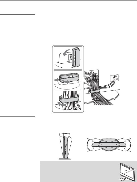
Bundling the
Connecting Cables
After the connections are done, organize the cables as illustrated below.
1Attach the cable holder (supplied) to the rear of the TV (A), then turn the cable holder a quarter turn to the left (B).
2Push the clasp lever in to release the lock and open the cover, and then insert the cables.
3Close the cover until it clicks shut and locks.
1 B
A |
2 |
3 |
Adjusting the
Viewing Angle of the
TV
This TV can be adjusted within the angles shown below.
Adjust the angle back and forth |
Adjust the angle left and right |
||
(tilt) (KDL-V26/32XBR1 only) |
(swivel) |
||
Right view |
3° |
8° |
Top view |
|
|
||
|
|
15° |
15° |
|
|
15° |
15° |
Front |
|
|
Front |
|
|
|
|
 When adjusting the angle, hold the stand with one hand to avoid slipping or tipping the stand.
14

Introducing the TV
TV Controls and Connectors
Front Panel
TV the Introducing
5
 PIC OFF
  TIMER
TIMER  POWER/STANDBY
|
|
|
|
|
|
|
|
|
|
|
|
|
|
|
|
1 |
2 |
3 |
4 |
||||||||
|
|
|
|
|
|
|
|
|
|
|
|
||
Item |
|
Description |
|
|
|
|
|
|
|
|
|
||
1 |
PIC OFF LED |
When lit, indicates that the Picture Off feature is activated. For details, see page 86. |
|||||||||||
|
|
|
|||||||||||
2 |
TIMER LED |
When lit, indicates one of the timers or Sleep is set. When it is set, this LED will remain lit |
|||||||||||
|
|
even if the TV is turned off. For details, see page 90. |
|
|
|
||||||||
|
|
|
|||||||||||
3 |
POWER/ |
Lights up in green when the TV is turned on. The LED lights up red when in standby mode for |
|||||||||||
|
STANDBY LED |
both TV and PC input. The standby mode for PC input is set by setting Power Management |
|||||||||||
|
|
to On in the PC Setup settings. If the LED blinks in red continuously, this may indicate the TV |
|||||||||||
|
|
needs servicing (see “Contacting Sony” on page 2). |
|
|
|
||||||||
|
|
|
|
|
|
||||||||
4 |
(IR) Infrared |
Receives IR signals from the remote control. |
|
|
|
||||||||
|
Receiver/Light |
Senses room light level and adjusts the screen brightness accordingly (for details, see page 86). |
|||||||||||
|
Sensor |
Do not put anything near the sensor, as its function may be affected. |
|||||||||||
|
|
|
|
|
|
|
|
|
|||||
5 |
Speaker |
Outputs audio signal. |
|
|
|
|
|
|
|||||
|
|
|
|
|
|
|
|
|
|
|
|
|
|
15

Introducing the TV
Side Panel
Left side
1
|
2 |
Y |
|
VIDEOLAUDIO(MONO)PR/CR PB/CB |
IN |
(1080i/720p/480p/480i)VIDEO/HD/DVD |
|
2 |
|
3 |
|
R |
|
4
Item |
Description |
Right side
POWER
5
CHANNEL 
 6
6
VOLUME 
 7
7
TV/VIDEO
8
WEGA 9
GATE
1 |
USB jack |
|
Connects to the USB port on your USB device. Provides a secure digital connection between |
|
|
|
your TV and USB device, such as digital video camcorders and digital cameras. |
|
|
|
|
2 |
VIDEO/HD/DVD |
Connect to your component video (YPBPR) and audio (L/R) output jacks of your DVD player |
|
|
2 IN |
|
or digital TV receiver. |
|
Y PB/CB PR/CR |
Component video provides better picture quality than the composite video (3) connection. |
|
|
|
|
|
3 |
VIDEO/HD/DVD |
Connect to the composite video and audio output jacks on your camcorder or other video |
|
|
2 IN |
|
equipment. When Auto is selected for the Video 2 (Component) option in the Setup |
|
VIDEO/(MONO) |
settings, the component video function will be preferentially activated (see page 86). |
|
|
L-AUDIO-R |
|
|
|
|
|
|
4 |
Headphones |
Connects to your headphones. If your headphones do not match the jack, use a suitable plug |
|
|
jack |
|
adaptor (not supplied). |
|
|
|
|
5 |
POWER |
|
Press to turn on and off the TV. |
|
|
|
|
6 |
V |
v |
Press to scan through channels. To scan quickly through channels, press and hold down either |
|
+ CHANNEL – |
+ or –. On the WEGA GATE screen, these buttons serve as up/down buttons. |
|
|
|
|
|
7 b |
B |
Press to adjust the volume. On the WEGA GATE screen, these buttons serve as right/left |
|
|
+ VOLUME – |
buttons. |
|
|
|
|
|
8 |
/TV/VIDEO |
Press to confirm the selection or setting in WEGA GATE. |
|
|
|
|
Press repeatedly to cycle through the video equipment connected to the TV’s video inputs. |
|
|
|
|
9 |
WEGA GATE |
Press to display WEGA GATE. Press again to exit WEGA GATE. |
|
|
|
|
|

 The CHANNEL + button has a tactile dot. Use the tactile dot as a reference when operating the TV.
16

Introducing the TV
Rear Panel
R |
AUDIO IN |
L |
|
|
6 |
|
|
Introducing |
|
|
|
|
|
||||
1 |
|
|
|
|
|
|
|
|
|
|
|
|
|
|
|
|
|
1 |
|
3 |
4 |
|
|
5 |
4 |
the |
S VIDEO |
|
|
Y |
|
OUT |
TV |
||
2 |
|
|
|
|
|
OPTICAL |
|
|
|
|
PB/CB |
|
|
|
|
||
|
|
|
|
|
|
|
||
|
|
VIDEO PR/CR |
|
|
5 |
|
||
|
|
|
|
|
|
|||
3 |
|
L |
|
L |
|
|
|
|
|
(MONO) |
|
|
|
6 |
|
||
|
|
AUDIO AUDIO |
|
|
|
|||
|
|
R |
|
R |
|
|
|
|
|
VIDEO IN |
|
HD/DVD IN |
AUDIO OUT |
|
|
||
|
|
(1080i/720p/480p/480i) |
(VAR/FIX) |
KDL-V32XBR1 |
||||
KDL-V26XBR1 |
|
|
|
|
|
|
||
|
7 |
|
|
KDL-V40XBR1 |
||||
|
|
|
|
|
|
|||
|
|
AUDIO |
|
RGB |
|
|
|
|
|
|
|
|
PC IN |
7 |
|
|
|
|
|
CableCARD |
|
|
|
|
||
9 |
8 |
|
|
|
|
|
0 |
qa |
CABLE |
|
0 |
|
|
|
CABLE |
|
|
|
|
|
|
|
|
|
||
|
|
qa |
9 |
|
|
|
||
VHF/UHF |
|
|
|
|
VHF/UHF |
|
||
AC IN |
AC IN |
(Continued)
17

Introducing the TV
Jack |
Description |
|
1 |
HDMI 6 IN |
HDMI (High-Definition Multimedia Interface) provides an uncompressed, all-digital |
|
HDMI/ |
audio/video interface between this TV and any HDMI-equipped audio/video component, such |
|
R-AUDIO IN-L |
as a set-top box, DVD player, and A/V receiver. HDMI supports enhanced, or high-definition |
|
|
video, plus two-channel digital audio. |
|
|
The AUDIO IN (L/R) of HDMI IN is for DVI connection. For details, see page 27. |
|
|
|
2 |
VIDEO 1 IN |
Connects to the S VIDEO output jack of your VCR or other video equipment that has |
|
S VIDEO |
S VIDEO. S VIDEO provides better picture quality than the composite video (3) connection. |
|
|
|
3 |
VIDEO 1/3 IN |
Connect to the composite video and audio output jacks on your VCR or other video |
|
VIDEO/ |
component. A third composite video and audio (VIDEO/HD/DVD 2 IN) is located on the left |
|
L (MONO)- |
side panel of the TV. |
|
AUDIO-R |
|
|
|
|
4 |
HD/DVD 4/5 IN |
Connect to your DVD player’s or digital set-top box’s component video (YPBPR) and audio |
|
(1080i/720p/ |
(L/R) jacks. |
|
480p/480i)/ |
Component video provides better picture quality than the S VIDEO (2) or the composite |
|
L-AUDIO-R |
video (3) connections. |
5OPTICAL OUT Connects to the optical audio input of a digital audio component that is PCM/Dolby Digital (PCM/DOLBY* compatible.
DIGITAL)
6 |
AUDIO OUT |
Connect to the left and right audio input jacks of your audio or video equipment. You can use |
|
(VAR/FIX) |
these outputs to listen to your TV’s audio through your stereo system. |
|
|
|
7 |
PC 7 IN |
Connects to personal computer’s video and audio output connectors. |
|
(AUDIO/RGB) |
Can be connected to other Analog RGB devices such as Video Conferencing or Set-top Boxes. |
|
|
See “PC Input Signal Reference Chart” on page 89 for the signal to be displayed. |
|
|
|
8 |
CableCARD slot |
CableCARD device provides cable subscribers with access to secure, digitally encrypted cable |
|
|
channels — without the need for a set-top box — that will enable you to receive not only |
|
|
standard definition but also high definition television. For details, see page 29. |
|
|
|
9 |
AC IN |
Connects the supplied AC power cord. |
|
|
|
0 |
CABLE |
RF input that connects to your cable signal. |
|
|
|
qa |
VHF/UHF |
RF input that connects to your VHF/UHF antenna. |
|
|
|
*Manufactured under license from Dolby Laboratories. “Dolby” and the double-D symbol are trademarks of Dolby Laboratories.
18
Connecting the TV
Overview
Your new LCD TV can receive both analog and digital (HD and SD) broadcasting signals from antenna, satellite and cable TV company.
To display clear crisp pictures, you must connect your TV correctly and choose the correct display format (see “Using the WIDE Button” on page 50). It is strongly recommended to connect the cable and antenna inputs using a 75-ohm coaxial cable to receive optimum picture quality signal. A 300-ohm twin lead cable can be easily affected by radio noise and the like, resulting in signal deterioration. If you use a 300-ohm twin lead cable, keep it as far away as possible from the TV.
TV the Connecting
Making Video and
Audio Connections
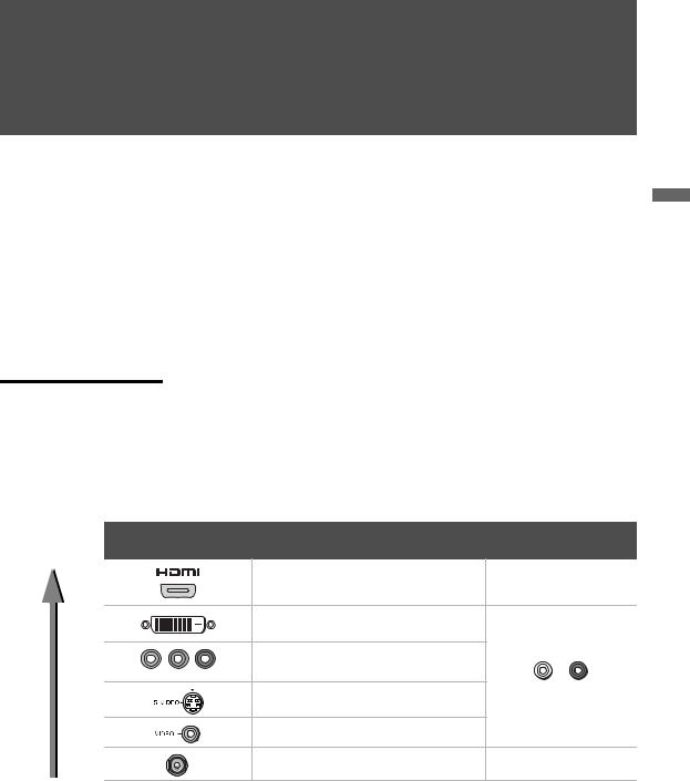
The signals that enter your TV and connected devices will need to output in the correct format using the suitable connections. Below are different types of video connectors available these days. Your TV comes with all types of connectors with the exception of the DVI connector but your cable box or satellite receiver may be equipped with this type. When connecting your TV, use the inputs that are available on your devices that provide the best video performance, as to below.
Best Video |
|
Separate audio |
Performance |
Connector type |
connection required |
|
HDMI |
No |
|
(High-Definition Multimedia Interface) |
|
|
|
|
|
DVI (Digital Visual Interface) * |
|
|
Component video |
Yes |
|
|
|
Y PB/CB PR/CR |
(480i/480p/720p/1080i) |
|
|
S VIDEO |
L-AUDIO-R |
|
|
|
|
Composite video |
|
|
RF/Coaxial |
No |
*An adapter is necessary when you are connecting a DVI-equipped device to this TV (see page 20).
19
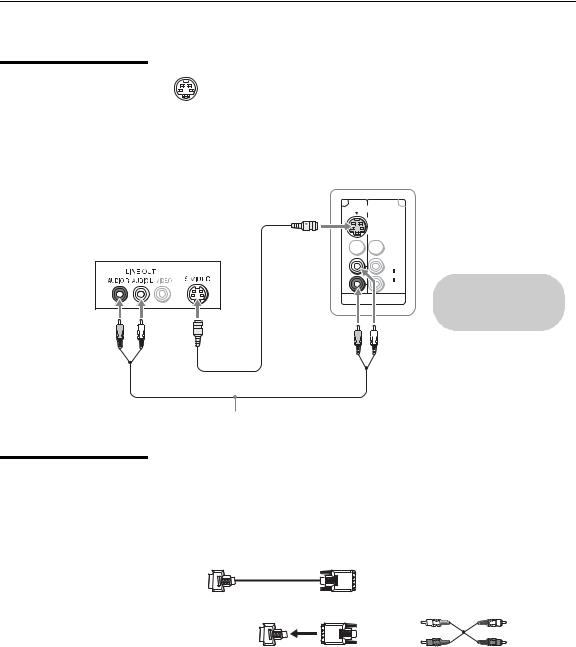
Connecting the TV
About Using S
VIDEO
If the optional equipment you are connecting has an S VIDEO jack (shown at left), you can use an S VIDEO cable for improved picture quality (compared to an A/V cable). Because S VIDEO carries only the video signal, you also need to connect audio cables for sound, as shown below.
Example of an S VIDEO Connection
Rear of TV
S VIDEO 
Equipment with S VIDEO
 S VIDEO cable
1 |
3 |
SVIDEO


 VIDEO
VIDEO
L
(MONO)
AUDIO
R
VIDEO IN
Cables are often color-coded to connectors. Connect red to red, white to white, etc.
Audio cable
About Using HDMI to DVI Adapter
If you are connecting equipment with DVI connector to this TV, you will need to use an adapter. You can use an HDMI-to-DVI cable or an HDMI adapter (not supplied). Both are available at your local electronics store.
When you use the adapter, you will also need to use separate audio cables for sound as DVI connector is for video signals only.
HDMI-to-DVI Cable
HDMI adapter |
Audio cable |
20
Connecting the TV
Basic Connections
Cable System or VHF/UHF
The way in which you connect your TV will vary, depending on how your home receives a signal (antenna and satellite; cable and cable box) and whether or not you plan to connect a VCR.
If You Are Connecting... |
See Page |
Cable System or VHF/UHF |
21 |
No cable box or VCR
Cable Box and Antenna |
22 |
Cable box unscrambles only some channels (usually premium channels)
No VCR
Cable Box |
23 |
Cable box unscrambles all channels
No VCR
Satellite Receiver |
24 |
Digital Cable Box or Digital Satellite Receiver |
25 |
Equipment with HDMI Connection |
26 |
Equipment with DVI Connection |
27 |
Equipment with Digital Audio (OPTICAL) |
28 |
|
|
If you are connecting a VCR
s See the connection described on pages 33 and 34.
For best results, use this connection if:
sYou have a cable and/or an antenna.
(This is convenient if you are using a separate rooftop antenna to receive additional channels that are not provided by your cable TV company.)
sYou do not have a cable box or VCR. (If you have a cable box, see pages 22 and 23. If you have a VCR, see pages 33 and 34.)
Antenna System
|
Cable Type |
Connect As Shown |
|
|
Cable TV (CATV) |
|
|
|
and Antenna |
Antenna cable |
CATV cable |
|
|
||
Notes on Using This Connection |
|
|
|
To Do This... |
Do This ... |
|
|
Switch the TV’s input between |
Press ANT to switch back and forth between the TV’s VHF/UHF and CABLE inputs. |
||
the cable and antenna |
|
|
|
 Do not use an indoor antenna, which is especially susceptible to radio noise.
TV the Connecting
21

Connecting the TV
Cable Box and
Antenna
Before connecting a cable box, see “Using CableCARD Device” on page 29.
For best results, use this connection if:
sYour cable company scrambles some channels, such as premium channels (which requires you to use a cable box), but does not scramble all channels.
sYou do not have a VCR. (If you have a VCR, see pages 33 and 34.)
With this connection you can:
sUse the TV’s remote control to change channels coming through the cable box to the TV’s CABLE input jack. (You must first program the remote control for your specific cable box; see “Programming the Remote Control” on page 44.)
sUse the TV’s remote control to change channels coming directly into the TV’s VHF/UHF input jack.
|
CATV cable |
IN OUT |
|
|
|
|
|
|
|
Cable box |
Coaxial |
|
|
|
|
|
|
|
cable |
|
Antenna cable |
VHF/UHF |
CABLE |
|
|
||
|
|
|
Rear of TV |
Notes on Using This Connection |
|
|
|
To Do This ... |
Do This ... |
|
|
Use the cable box |
Tune the TV to the channel the cable box is set to (usually channel 3 |
||
|
or 4) and then use the cable box to switch channels. |
||
Set up the TV remote control to operate the cable |
Program the remote control. See “Programming the Remote |
||
box |
Control” on page 44. |
|
|
Activate the remote control to operate the cable |
Press SAT/CABLE (FUNCTION). |
|
|
box |
|
|
|
Prevent the accidental switching of TV channels |
When using the cable box, ensure that the TV remains tuned to the |
||
|
channel that the cable box is set to (usually channel 3 or 4). |
||
Switch the TV’s input between the cable box and |
Press ANT to switch back and forth between the TV’s VHF/UHF |
||
antenna |
(scrambled channels) and CABLE (unscrambled) inputs. |
||
22

Cable Box
Before connecting a cable box, see “Using CableCARD Device” on page 29.
Connecting the TV
For best results, use this connection if:
sYour cable company scrambles all channels, which requires you to use a cable box.
sYou do not have a VCR. (If you have a VCR, see pages 33 and 34.)
With this connection you can:
s |
Use the TV’s remote control to change channels coming through the |
Connecting |
||
|
||||
|
cable box to the TV’s VHF/UHF input jack. (You must first program the |
|
||
|
remote control for your specific cable box.) |
|
||
To connect the cable box |
the |
|||
1 |
Connect the CATV cable to the cable box’s input jack. |
|||
TV |
||||
2 |
Use a coaxial cable to connect the cable box’s output jack to the TV’s |
|||
|
||||
|
VHF/UHF input jack. |
|
||
3 |
Run Auto Program, as described in “Setting Up the Channel List” on |
|
||
|
page 31. |
|
|
|
|
CATV cable |
Coaxial cable |
|
|
|
|
VHF/UHF |
|
|
Rear of TV
IN |
OUT |
|
|
|
Cable box |
Notes on Using This Connection |
|
To do this... |
Do This ... |
Use the cable box |
Tune the TV to the channel the cable box is set to (usually channel 3 |
|
or 4) and then use the cable box to switch channels. |
|
|
Set up the TV remote control to operate the cable |
Program the remote control. See “Programming the Remote |
box |
Control” on page 44. |
|
|
Activate the remote control to operate the cable |
Press SAT/CABLE (FUNCTION). |
box |
|
|
|
Prevent the accidental switching of TV channels |
When using the cable box, ensure that the TV remains tuned to the |
|
channel that the cable box is set to (usually channel 3 or 4). |
|
|
23

Connecting the TV |
|
|
|
|
|
Satellite Receiver |
Disconnect all power sources before making any connections. |
|
|
1 |
Connect the satellite antenna cable to the satellite receiver’s |
|
|
SATELLITE IN jack. |
|
2 |
Use A/V and S VIDEO cables to connect the satellite receiver’s AUDIO |
|
|
and S VIDEO OUT jacks to the TV’s AUDIO and S VIDEO IN jacks. |
|
3 |
Use a coaxial cable to connect your cable to the TV’s CABLE jack, or |
|
|
your antenna to the TV’s VHF/UHF jack. |
Rear of TV
1 |
3 |
|
|
VIDEO |
|
|
L |
|
|
(MONO) |
CABLE |
AUDIO  R
R
VHF/UHF
VIDEO IN
Coaxial cable
Cables are often color-coded to connectors. Connect red to red, white to white, etc.
S VIDEO |
VIDEO |
Satellite receiver |
|
AUDIO-L |
|
|
AUDIO-R |
|
Satellite antenna cable
A/V cable
S VIDEO cable

 If your satellite receiver is not equipped with S VIDEO, use a VIDEO cable (yellow) instead of the S VIDEO cable.
24

Digital Cable Box or Digital Satellite Receiver
Connecting the TV
Disconnect all power sources before making any connections.
1 Connect the RF coaxial cable from the CATV or satellite dish to the input of the digital cable box or digital satellite receiver.
2 Use a component video cable to connect the YPBPR jacks of your
|
digital cable box or digital satellite receiver to the TV’s component |
|
|
|
|
|
|
||
|
jacks. |
Connecting |
||
|
|
|||
|
Component video (Y PB/CB PR/CR) connection is necessary to view |
|||
|
|
|
||
|
digital broadcastings in 1080i, 720p, 480i and 480p. This TV |
|
|
|
|
displays all format types of picture in a resolution of 1,366 dots × |
|
|
|
|
768 lines. |
the |
||
3 |
Use an audio cable to connect the AUDIO OUT jack of the digital cable |
|||
TV |
||||
|
box or digital satellite receiver to the TV’s AUDIO IN jacks. |
|||
|
|
|
||


 The component Jacks (Y PB/CB PR/CR) do not provide audio, so audio cables must be connected to provide sound.
Digital cable box or Satellite receiver |
Y |
|
|
|
PB/CB |
|
PR/CR |
Rear of TV
Component video cable
4 |
5 |
|
Y |
OPTICAL
OUT
PB/CB
PR/CR
L
AUDIO
R
HD/DVD IN |
AUDIO OUT |
(1080i/720p/480p/480i) (VAR/FIX)
RF coaxial cable
AUDIO-L
Audio cable
AUDIO-R
Cables are often color-coded to connectors. Connect red to red, white to white, etc.
25

Connecting the TV
Equipment with HDMI Connection
zThe HDMI jack provides both video and audio signals, so it is not necessary to connect the audio cable.
For best results, use this connection if:
s Your equipment has a High-Definition Multimedia Interface (HDMI).
Disconnect all power sources before making any connections
Use an HDMI cable, connect the equipment’s HDMI OUT jack to the TV’s HDMI IN jack.
HDMI cable
Equipment with HDMI output |
Rear of TV |
|
R AUDIO IN |
L |
6 |
|
|
|
|
|
1 |
3 |
4 |
5 |
S VIDEO |
|
Y |
OPTICAL |
|
|
|
|
|
|
|
OUT |
|
|
PB/CB |
|
|
VIDEO PR/CR |
|
|
|
L |
L |
|
|
(MONO) |
|
|
|
AUDIO AUDIO |
|
|
|
R |
R |
|
VIDEO IN |
HD/DVD IN |
AUDIO OUT |
|
(1080i/720p/480p/480i) |
(VAR/FIX) |
||
26

|
Connecting the TV |
|
|
Equipment with DVI |
Disconnect all power sources before making any connections |
Connection |
If you are connecting with DVI-HDTV output, you can connect to the TV’s |
|
HDMI IN jack by using an HDMI-to-DVI cable or an adaptor. |
HDMI-to-DVI cable or adapter
Audio cable
AUDIO-L
AUDIO-R
Equipment with DVI output
Cables are often color-coded to connectors. Connect red to red, white to white, etc.
|
|
Rear of TV |
|
R AUDIO IN |
L |
6 |
|
|
|
|
|
1 |
3 |
4 |
5 |
S VIDEO |
|
Y |
OPTICAL |
|
|
|
|
|
|
|
OUT |
|
|
PB/CB |
|
|
VIDEO PR/CR |
|
|
|
L |
L |
|
|
(MONO) |
|
|
|
AUDIO AUDIO |
|
|
|
R |
R |
|
VIDEO IN |
HD/DVD IN |
AUDIO OUT |
|
(1080i/720p/480p/480i) |
(VAR/FIX) |
||
TV the Connecting

 When using an HDMI-to-DVI cable or an adapter, be sure to connect the DVI output connector first; then connect to the HDMI input on your TV.
27

Connecting the TV
Equipment with Digital Audio (OPTICAL)
Disconnect all power sources before making any connections.
You can use the TV's OPTICAL OUT jack to connect a digital audio device that is PCM/Dolby digital compatible, such as an audio amplifier.
Use an optical audio cable to connect the TV’s OPTICAL OUT jack to the device’s OPTICAL IN jack.
Rear of TV
4 |
5 |
|
Y |
OPTICAL
OUT
PB/CB
PR/CR
L
AUDIO
R
HD/DVD IN |
AUDIO OUT |
(1080i/720p/480p/480i) (VAR/FIX)
 Optical audio cable
|
The OPTICAL OUT jack is |
|
Audio amplifier |
available only when a |
|
digital TV channel is |
||
|
||
LINE |
received. |
|
|
||
OUT |
|
|
L AUDIO R |
OPTICAL |
|
LINE |
||
IN |
||
IN |
||
|
28

Connecting the TV
Using CableCARD Device
About Using
CableCARD Device
Activating
CableCARD Service
CableCARD device provides cable subscribers with access to digitally encrypted cable channels — without the need for a set-top box — that will enable you to receive not only standard definition but also high definition television. The CableCARD device, which is provided by your cable TV company, is inserted into the TV’s rear panel CableCARD slot. After the service is activated with your cable TV company, the card replaces the need for a separate set-top box.
If you are planning to use a separate cable box for digital cable TV services, you may be able to receive programming using this TV with the CableCARD device instead — except in the following circumstances:
sYour cable TV company does not provide CableCARD service in your viewing area.
sYou want to access your cable TV company’s interactive or advanced features (such as video-on-demand or, in some cases, pay-per-view). At this time, these services require a bidirectional link, which are only available through the use of a separate set-top box. The CableCARD device is currently a unidirectional device only, and cannot provide these advanced services.
Check with your cable TV company for CableCARD service details, limitations, pricing, and availability, all of which are determined by your cable TV company — not Sony.
Before you can use CableCARD service, you need to insert the CableCARD device (supplied by your cable TV company) and activate the service, as described below:
1Remove the cover and insert the CableCARD device into the TV’s CableCARD slot.
TV the Connecting
AUDIO
RGB |
|
PC |
|
IN |
7 |
CableC |
ARD |
|
(Continued)
29

Connecting the TV
zYou can also access information about your CableCARD device in the Applications settings (see page 91).
Removing the
CableCARD Device


 CAUTION: Inserting the CableCARD device incorrectly may result in permanent damage to the card and the TV.
2Gently push the card into the slot until it locks into place, and then reattach the cover.
3After 1-2 minutes, the CableCARD device setup screen is automatically displayed. This screen includes information your cable TV company will request before they can activate your service.
4Follow the displayed instructions: Phone your cable TV company. A representative will guide you through the activation process.
5After your CableCARD device is activated, your cable TV company will download the service information, including the channel list, to the CableCARD device. After the CableCARD device has acquired channels from your cable TV company, the TV tunes to the lowest available channel.
In the event you want to cancel your service, contact your cable TV company.


 Once the CableCARD device is removed, your TV will no longer decrypt digital cable TV programming services that require CableCARD device.
1 Push the eject button on the TV’s CableCARD slot to release the card.
AUDIO
RGB |
|
PC |
|
IN |
7 |
CableCARD
Eject button
2 Pull the CableCARD device straight out of the slot to remove it.
To install a different CableCARD device, follow the instructions in “Activating CableCARD Service” on page 29.
30
Loading...