


SERVICE MANUAL
S383FA-V151
P/N : 41A50-137
THESE DOCUMENTS ARE FOR REPAIR SERVICE INFORMATION ONLY. EVERY REASONABLE EFFORT HAS BEEN MADE TO ENSURE THE ACCURACY OF THIS MANUAL; WE CANNOT GUARANTEE THE ACCURACY OF THIS INFORMATION AFTER THE DATE OF PUBLICATION AND DISCLAIMS RE LIABILITY FOR CHANGES, ERRORS OR OMISSIONS,
MANUFACTURE DATA : NOVEMBER. 2000
1
PAGE |
|
TABLE OF CONTENTS |
|
|
|
|
|
1. |
SPECIFICATIONS .................................................................................................... |
3 |
|
|
1-1 |
GENERAL SPECIFICATIONS ...................................................….............. |
3 |
|
1-2 |
LCD MONITOR DESCRIPTION .................................................................. |
4 |
|
1-3 |
INTERFACE CONNECTOR .................................................................……. |
4 |
2. |
PRECAUTION AND NOTICES ................................................................................ |
5 |
|
|
2-1 |
ASSEMBLY PRECAUTION ......................................................................... |
5 |
|
2-2 |
OPERATIONG PRECAUTION ..................................................................... |
5 |
|
2-3 |
STORAGE PRECAUTION …........................................................................ |
5 |
|
2-4 HIGH VOLTAGE WARNING ....................................................................... |
5 |
|
3. |
OPERATING INSTRUCTIONS ................................................................................ |
6 |
|
4. |
ADJUSTMENT .......................................................................................................... |
7 |
|
|
4-1 ADJUSTMENT CONDITIONS AND PRECAUTIONS ............................... |
7 |
|
|
4-2 |
ADJUSTMENTS METHOD ........................................................................... |
7-8 |
|
4-3 FRONT PANEL CONTROL KNOBS ............................................................ |
8 |
|
5. |
CIRCUIT DESCRIPTION .......................................................................................... |
9 |
|
|
5-1 THE DIFFERENT BETWEEN EACH PANEL ……………………………. |
9 |
|
|
5-2 SPECIAL FUNCTION WITH PRESS KEY ……………………………….. |
9 |
|
|
5-3 SIMPLE INTRODUCTION ABOUT LM500 CHIPSET …………………... |
10 |
|
6. |
TROUBLE SHOOTING CHART .............................................................................. |
11 |
|
7. |
MECHANICAL OF CABINET FRONT DIS-ASSEMBLY...................................... |
45 |
|
8. |
PARTS LISTING .........................................................................................………... |
46 |
|
9. |
POWER SYSTEM AND CONSUMPTION CURRENT............................................ |
51 |
|
|
9-1 HARDWARE BLOCK DIAGRAM ………………………………………… |
52 |
|
10. |
PCB LAYOUT .....................................................................………………………... |
53 |
|
11. |
SCHEMATIC DIAGRAM …..................................................................................... |
54 |
|
2
1. SPECIFICATIONS FOR LCD MONITOR
1-1 General specifications |
|
1. LCD-PANEL : |
|
Active display area |
15 inches diagonal |
Pixel pitch |
0.298 mm x 0.298 mm |
Pixel format |
1024 x 768 RGB vertical stripe arrangement |
2.Display Color : 6-bit, 262144 colors
3.External Controls :
Power On/Off, Auto key, Rotary-knob, Contrast, Brightness, Focus, Clock, H-position, V-position, Language, Recall-7800, Recall-6500, Reset, Exit-osd, Red, Green, Blue
4.Input Video Signal : Analog-signal 0.7Vpp
Video signal termination impedance 75 OHM
5.Scanning Frequencies :
Horizontal: |
29 |
KHz - 61 KHz |
Vertical: |
55 |
Hz – 75 Hz |
Pixel clock: |
80 |
MHz |
6.Factory Preset Timing : 18 User Timings : 19
Input signal tolerance : H tolerance  1 K, V tolerance
7.Power Source :
Switching Mode Power Supply
AC 100 – 240 V, 50/60 Hz Universal Type
8.Operating Temperature : 0 - 50 Ambient Non-operating Temperature : -20 - 60
9.Humidity :
Operating : 20% to 80% RH (non-condensing)
Non Operating : 5% to 95%RH (38.7 maximum wet bulb temperature)
10.Weight :
4.6kg
11.External Connection : 15Pin D-type Connector, AC power-Cord
12.View Angle : x-axis right/left = 60, y-axis up/down = 45
13.Outside dimension : Width x Height x Thickness = 398mm x 401mm x 250mm
14.Plug and Play : VESA DDC1/DDC2B
15.Power saving : VESA DPMS
3
1-2 LCD MONITOR DESCRIPTION
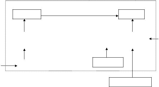
The LCD MONITOR will contain an main board, an inverter board, a power switch board and a keyboard. The main board will house the flat panel control logic, brightness control logic, DDC and DC-DC conversion to supply the appropriate power to the whole board and LCD panel, and transmitting TTL level signals into LCD Module to drive the LCD display circuit.
The inverter board will drive the two CCFLs (Cold Cathode Fluorescent Tube).
The switching power board will provides the power ON/OFF control over the whole monitor and control for DPMS LED indicator.
The function keyboard will provides the OSD control signal to the Main Board.
Monitor Block Diagram
|
CCFT Drive. |
Inverter |
Flat Panel |
|
|
|
Main Board |
|
RS232 Connector |
|
|
|
|
|
|
AC-IN
ADAPTER |
Keyboard |
|
|
|
|
HOST Computer |
Video signal, DDC |
|
1-3 Interface Connectors
(A)Power Cable
(B)Video Signal Connectors and Cable
4

2. PRECAUTIONS AND NOTICES
2-1 ASSEMBLY PRECAUTION
(1)Please do not press or scratch LCD panel surface with anything hard. And do not soil LCD panel surface by touching with bare hands (Polarizer film, surface of LCD panel is easy to be flawed)
In the LCD panel, the gap between two glass plates is kept perfectly even to maintain display characteristic and reliability. If this panel is subject to hard pressing, the following occurs :
(a) Uniform color (b) Orientation of liquid crystal becomes disorder
(2)Please wipe out LCD panel surface with absorbent cotton or soft cloth in case of it being soiled.
(3)Please wipe out drops of adhesive like saliva and water in LCD panel surface immediately. They might damage to cause panel surface variation and color change.
(4)Do not apply any strong mechanical shock to the LCD panel.
2-2 OPERATING PRECAUTIONS
(1)Please be sure to unplug the power cord before remove the back-cover. (be sure the power is turn-off)
(2)Please do not change variable resistance settings in MAIN-BOARD, they are adjusted to the most suitable value. If they are changed, it might happen LUMINANCE does not satisfy the white balance spec.
(3)Please consider that LCD backlight takes longer time to become stable of radiation characteristic in low temperature than in room temperature.
(4)Please pay attention to displaying the same pattern for very long-time. Image might stick on LCD.
2-3 STORAGE PRECAUTIONS
(1) When you store LCD for a long time, it is recommended to keep the temperature between 0 |
|
without |
|
||
the exposure of sunlight and to keep the humidity less than 90% RH. |
|
|
(2)Please do not leave the LCD in the environment of high humidity and high temperature such as 60 90%RH.
(3)Please do not leave the LCD in the environment of low temperature; below -15 .
2-4 HIGH VOLTAGE WARNING
The high voltage was only generated by INVERTER module, if carelessly contacted the transformer on this module, can cause a serious shock. (the lamp voltage after stable around 600V, with lamp current around 8mA, and the lamp starting voltage was around 1500V, at Ta=25 )
5

3. OPERATING INSTRUCTIONS
This procedure gives you instructions for installing and using the LM500 LCD monitor display.
1.Position the display on the desired operation and plug the power cord into a convenient AC outlet. Threewire power cord must be shielded and is provided as a safety precaution as it connects the chassis and cabinet to the electrical conduct ground. If the AC outlet in your location does not have provisions for the grounded type plug, the installer should attach the proper adapter to ensure a safe ground potential.
2.Connect the 15-pin color display shielded signal cable to your signal system device and lock both screws on the connector to ensure firm grounding. The connector information is as follow:
1 |
5 |
6 |
10 |
|
|
11 |
15 |
15 - Pin Color Display Signal Cable
PIN NO. |
DESCRIPTION |
PIN NO. |
DESCRIPTION |
|
|
|
|
1. |
RED |
9. |
5V power from VGA-card |
2. |
GREEN |
10. |
GND |
3. |
BLUE |
11. |
SYNC. GND |
4. |
GND |
12. |
SDA |
5. |
GND |
13. |
HORIZ. SYNC |
6. |
GND-R |
14. |
VERT. SYNC |
7. |
GND-G |
15. |
SCL |
8. |
GND-B |
|
|
3.Apply power to the display by turning the power switch to the "ON" position and allow about thirty seconds for Panel warm-up. The Power-On indicator lights when the display is on.
4.With proper signals feed to the display, a pattern or data should appear on the screen, adjust the brightness and contrast to the most pleasing display, or press auto-key to get the best picture-quality.
5.This monitor has power saving function following the VESA DPMS. Be sure to connect the signal cable to the PC.
6.If your LM500 LCD monitor requires service, it must be returned with the power cord.
6
4. ADJUSTMENT
4-1 ADJUSTMENT CONDITIONS AND PRECAUTIONS
1.Approximately 30 minutes should be allowed for warm up before proceeding.
2.Adjustments should be undertaken only on following function : contrast, brightness focus, clock, h-position, v-position, red, green, blue since 6500 color & 7800 color &VR501 have been carefully preset at the factory.
4-2 ADJUSTMENT METHOD
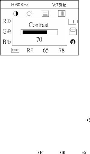
Press MENU key to show OSD window or select function, and Left/Right key to switch the function controls or done the adjustment.
1.White-Balance, Luminance adjustment
Before started adjust white balance ,lets setting the Chroma-7120 MEM. Channel 3 to 7800 color and MEM. channel 4 to 6500 color, how to setting MEM.channel you can reference to chroma 7120 user guide or simple use “ SC” key and “ NEXT” key to modify xyY value and use “ID” key to modify your own description
Following is the step to do white-balance adjust
Press MENU key for 2 seconds at power on (replug power cord) will be in factory mode, and the OSD screen will located at left top of panel.
I. Bias (Low luminance) adjustment :
Press “ AUTO” key , and wait for message “ Pass” appear then set OSD contrast and brightness
To maximal, RGB to “50” . then adjust VR501 until Y=210 cd/m2 |
cd/m2 |
||
II. Gain (High light) adjustment : |
|
|
|
a. adjust 7800 color-temperature |
|
|
|
Set OSD contrast = 15, Brightness = -10 |
|
|
|
Switch the chroma-7120 to RGB-mode(with press “MODE” ) |
|
||
,and selected the MEM.channel to Channel 03 |
|
cd/m2 |
|
The lcd-indicator will show x = 296 |
, y = 311 |
, Y = 135 |
|
Adjust RGB until R=100, G=100, B=100, and then switch the chroma-7120 to xyY mode (With press “MODE” )
Adjust contrast until Y= 150 cd/m2
Press osd-78 to save in 7800 factory mode
b. adjust 6500 color-temperature
Set OSD contrast = 15, Brightness = -10 Switch the chroma-7120 to RGB-mode(with press “MODE” ),and selected the MEM.channel to Channel 04
The lcd-indicator will show x = 313 
 , y = 329
 , Y = 135
 cd/m2
cd/m2
Adjust RGB until R=100, G=100, B=100, and then switch the chroma-7120 to xyY mode Adjust contrast until Y= 150 cd/m2 ,Press osd-65 to save in 6500 factory mode
Press POWER-key off-on to quit from factory mode ( in USER-mode, the OSD location was placed at middle of screen)
7
2.Clock adjustment
Set the Chroma at pattern 63 (cross-talk pattern) or WIN98/95 shut-down mode (dot-pattern). Adjust until the vertical-shadow as wide as possible or no visible.
This function is adjust the PLL divider of ADC to generate an accurate pixel clock Example : Hsyn = 31.5KHz Pixel freq. = 25.175MHz (from VESA spec)
The Divider number is (N) = (Pixel freq. x 1000)/Hsyn
From this formula, we get the Divider number, if we fill this number in ADC register (divider register), the PLL of ADC will generate a clock which have same period with above Pixel freq.(25.175MHz) the accuracy of this clock will effect the size of screen.(this clock was called PIXEL-CLOCK)
3.Focus adjustment
Set the Chroma at pattern 63 (cross talk pattern) or WIN98/95 shut down mode (dot-pattern). Adjust the horizontal interference as less as possible
This function is adjust the phase shift of PIXEL-CLOCK to acquire the right pixel data .
If the relationship of pixel data and pixel clock not so match, we can see the horizontal interference at screen only at crosstalk pattern and dot pattern we can find this phenomena, other pattern the affect is very light
4.H/V-Position adjustment
Set the Chroma at pattern 1 (crosshatch pattern) or WIN98/95 full-white pattern confirm above 2 functions (clock & focus) was done well, if that 2 functions failed, the H/V position will be failed too. Adjust the four edge until all four-edges are visible at the edge of screen.
5.MULTI-LANGUAGE function
There have 5 language for selection, press “MENU” to selected and confirm , press “ LEFT” or “ RIGHT” to change the kind of language.
6.Reset function
Clear each old status of auto-configuration and re-do auto-configuration ( for all mode)
This function also recall 7800 color-temperature , if the monitor status was in “ Factory-mode” this reset function will clear Power-on counter too.
7.OSD-LOCK function
Press Left & Right key during switching on the monitor, the access to the OSD is locked, user only has access to “ Contrast, Brightness, Auto-key “.
If the operator pressed the Left & Right during switching on the monitor again , the OSD is unlocked.
8.View Power-on counter and reset the Power-on counter( if not necessary , not suggest to entry factory mode)
The Power-on counter was used to record how long the backlight of panel already working, the backlight life time was guarantee minimal 25000 hours, the maintainer can check the record only in factory mode. Press MENU key for 2 seconds at power on (replug power cord) will be in factory mode, and the OSD screen will located at left top of panel but take cautions don’t press icon “78” & “65”, if you press 78/65 , your white-balance data will overlap with the new-one, and you must perform the white-balance process again.
The result of counter was place at top of OSD, the maximal of record memory was 65000 hours, if exceed 65000 hours the counter will keep in 65000 hours until press “ RESET” at osd-menu in factory mode. The “ RESET” function in factory mode will execute following function :
1.clear the Power-on counter to zero hours
2.clear old auto-configuration status for all mode , so the monitor will automatically re-do auto-config when change to next mode or power on-off
4-3 MAIN ADJUSTMENTS
Power Key : Press to turn on or off the monitor.
Auto Key : Press to perform automatic calculated CLOCK, FOCUS, H/V POSITION, but no affect the colortemperature
Left/Right Key : press to perform select function or adjustment.
MENU Key : press to show the OSD menu at the monitor or to confirm your function selection
8
|
|
5. CIRCUIT-DESCRIPTION |
5-1 THE DIFFERENT |
between |
LG-Panel & Samsung-Panel & CPT-Panel & HannstarPanel in |
ELECTRICAL Charateristic |
|
|
LG-Panel |
1. Two CCFL (Cold Cathode Fluorescent Tube) |
|
|
2. |
Single Pixel, 6 bit color (262144 colors) |
|
3. |
Panel Vdd = 3.3V (in JP202 select 3.3V) |
Samsung-Panel 1. Four CCFL (Cold Cathode Fluorescent Tube)
2.Double Pixel, 6 bit color (262144 colors)
3.Panel Vdd = 5V (in JP201 select 5V)
Chung-Hwa Panel |
1. |
Two CCFL (Cold Cathode Flourescent Tube) |
|
2. |
Double Pixel, 8 bit color (16.7 Million colors) |
|
3. |
Panel Vdd = 5V (in JP201 select 5V) |
Hannstar Panel 1. Two CCFL (Cold Cathode Flourescent Tube)
2.Double Pixel, 6 bit color (262144 colors)
3.Panel Vdd = 3.3V (in JP202 select 3.3V)
5-2 SPECIAL FUNCTION with PRESS-KEY
press ENTER-key 2 seconds, at POWER-ON: set to FACTORY-mode, when we want to adjust white-balance with rs232-port or view Power-on-timer. In this mode, OSDscreen will locate in left top of screen.
Press POWER-key off-on : CANCEL above function(quit from factory mode) and set to user-mode. Press both Left & Right key and switching on-off key : Enable/ Disable OSD-LOCK function
OSD-INDEX EXPLANATION
1.CABLE NOT CONNECTED : Signal-cable not connected.
2.INPUT NOT SUPPORT :
a.INPUT frequency out of range : H > 62kHz, v > 75Hz or H < 28kHz, v < 55Hz
b.INPUT frequency out of VESA-spec. (out of tolerance too far)
3.UNSUPPORT mode, try different Video-card Setting :
Input frequency out of tolerance, but still can catch-up by our system (if this message show, that means, this is new-user mode, AUTO-CONFIG will disable)
9
5-3 SIMPLE-INTRODUCTION about LM500 chipset
1.GMZAN1 (Genesis all-in-one solution for ADC, OSD, scalar and interpolation) :
USE for computer graphics images to convert analog RGB data to digital data for interpolation process, zooming, OSD font & overlay and generate drive-timing for LCD-PANEL,
2.M6759 (ALIMCU, type 8052 series with 64k Rom-size and 512 byte ram) :
Use for calculate frequency, pixel-dot , detect change mode, rs232-communication, power-consumption control, OSD-index warning…etc.
3.24LC21 (MicroChip IC) :
EePROM type, 1K ROM-SIZE, for saving DDC-CONTENT.
4.24C04 (ATMEL IC) :
EePROM type, 4K ROM-SIZE, for saving AUTO-config data, White-balance data, and Power-key status and power on –counter data.
5.LM2569S( NS brand swintching regulator 12V to 5V with 3A load current) :
6.AIC 1084-33CM (AIC brand linear regulator 5V to 3.3V)
MODULE-TPYE COMPONENT :
1.ADAPTER : CONVERSION-module to convert AC 110V-240V to 12VDC, with 3.5 AMP
2.INVERTER : CONVERSION-module to convert DC 12V to High-Voltage around 1600V, with frequency 30K-50Khz, 7mA-9mA
10

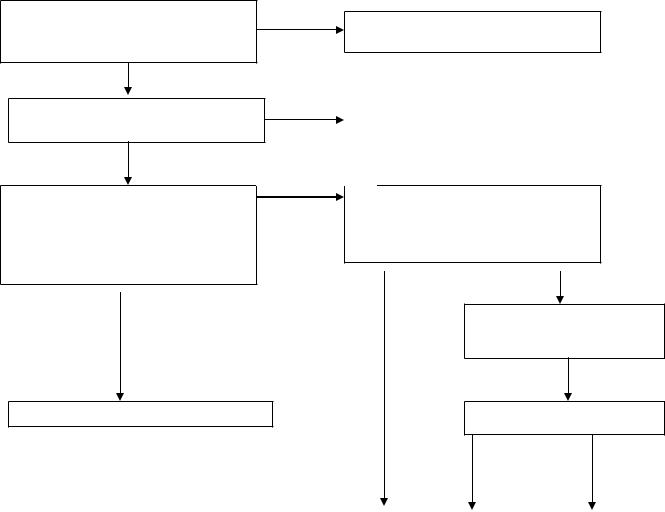
6. Trouble-Shooting
**Use the PC Win 98/95 white pattern, with some icon on it, and Change the Resolution to 640x480 60 Hz / 31 KHz
**NOTICE : This system free-running freq. is 48 KHz / 60 Hz, so you better use another frequency to do trouble shooting(ex:31kHz 60Hz) this trouble shooting is proceed with 640x480 @60Hz 31Khz
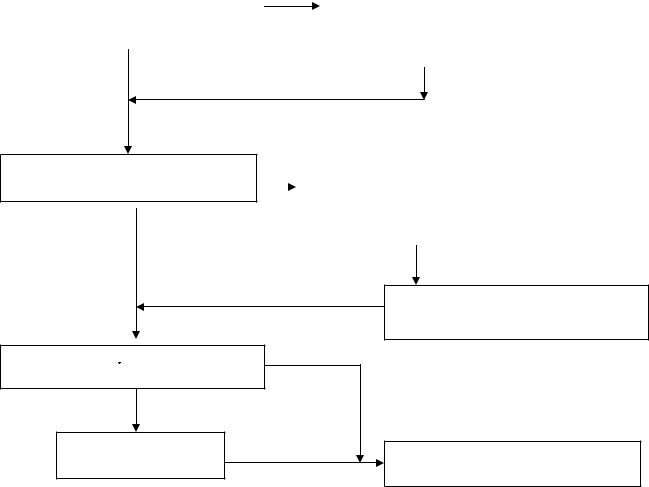
I.NO SCREEN APPEAR
OK, led in green-state
But still no screen Re-plug power cord & make sure LED was in green-state? If led is in off-state(dark), press
POWER-button to power-on the monitor
NG, led in dark |
||
NG, led in orange |
If LED in DARK-state, check the key- |
|
|
Button ,it could be stuck by mechanical |
|
If LED in ORANGE-state, check your |
||
signal-cable |
|
|
|
Check Keyboard circuit and check |
|
|
Mechanical key button, why be stuck? |
|
OK, still no screen |
NG, still in led |
|
But led is in Green |
||
ORANGE |
||
|
||
Replace INVERTER to new-one, and |
GMZAN1-BLOCK |
|
Check the screen is normal ?? |
|
|
|
OK, screen is normal |
|
|
White-balance |
|
Check INVERTER-module |
||
NG |
|
|
Check the FPC cable from CN201,CN202 |
NG |
|
was tight enough?, check the FPC of |
RE-assemble the FPC cable for both side |
|
(Cn201,202 & panel-side) |
||
panel side too |
||
|
||
OK |
|
|
Measured all power path if have had |
|
|
power? |
Check Power-Block |
|
|
||
C309, C310= 5V ?, C312=3.3V ?,U302 |
|
|
MCU pin 44=5V ? |
|
|
OK
Check crystal & oscillator if keep normal? |
|
NG |
|
Check Oscillator & crystal relative circuit |
(for MCU crystal 20MHz, for GMZAN1 |
|
|
|
Or replace |
|
|
|
||
oscillator 50MHz) |
|
|
|
|
R215= 50M Hz ? U302 pin 20= 20 M Hz ? |
|
|
|
|
|
|
|
|
|
|
|
|
|
|
OK |
|
|
|
|
11
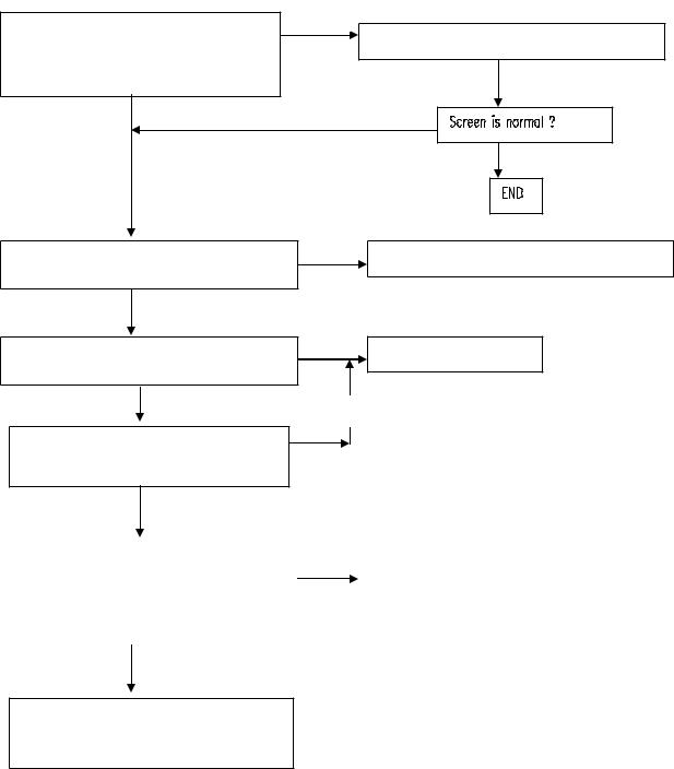
Check MCU reset circuit if normal ? U302 pin 10 = low to high when Power-on??
OK
Check R229 reset for GMZAN1= high to Low twice when power-on ??
OK
Measured PCLK(pin 44 from CN201) OK
PVS,PHS (pin 40,38 from CN201) Is there has any transition?
Pclk =31.25MHZ ,PVS=60.09Hz , PHS =50.4KHz ??(for input signal=31K 60 Hz)
OK,there have transition
Check PERIPHERAL PANEL BLOCK
NG
Check MCU relative reset circuit
C313, R313, D301 !!
NG |
Check GMZAN1 relative reset circuit |
|
R326,C314,D302,R229 |
|
|
NG, no transition
Check input connector CN200 is loose?? Measure R212,R211= 31K & 60 hz?? Measure R200,R201,R202 (RGB input ) had signal??
OK |
NG |
Tighten CN200 Cable & check
Relative Circuit
Screen normal & appear?
NG |
|
OK |
|
|
|
|
|
Check GMZAN1-BLOCK |
|
END |
|
|
|
|
|
12
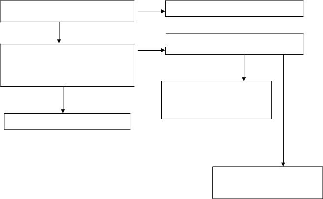
PERIPHERAL PANEL BLOCK
Note: “Panel vdd “ and “backlight on-off ” can be direct control by :
|
GMZAN1 or MCU |
|
|
|
Some panel can direct control by GMZAN1 ,if the relative timing between panel-vdd and backlight on-off |
||||
is short ( under 80 ms) , otherwise, will be control by MCU |
||||
If |
J211 be connected, that means Panel-VDD control was by GMZAN1 ,otherwise by MCU( JP212) |
|||
If |
J300 be connected, that means Backlight control was by GMZAN1 ,otherwise by MCU ( JP301) |
|||
BUT Hannstar panel & CPT panel still control by J211 & J300 |
||||
|
|
|
|
|
|
|
|
If JP211 was connected, check PPWR relative circuit |
|
Press on-off key once, make-sure Led is in |
|
|||
NG |
( R400,R401,Q250,R223,Q200,R224,R225,C245,Q201 |
|||
Green state .check panel-VDD = 3.3V for |
||||
cold-solder or open loop)?? make-sure LED in |
||||
HANNSTAR |
|
|||
|
Green-state, and PPWR (U200.pin 76)= high 3.3V |
|||
And 5V for CPT-panel , measured Panel-p |
|
|||
|
If JP212 was connected, check Backlight_En relative circuit |
|||
(pin 4,5 from CN201)?? |
|
|||
|
(R223,Q200,R224,R225,Q201,C245), make sure |
|||
|
|
|
||
|
|
|
Backlight_En = low 0V ?? |
|
|
OK |
|
||
|
|
|
||
|
|
OK |
||
|
|
|
||
Check CN303 pin 3 = 5 V ? ( that is Backlight controller, On-state= 5V)
OK
NG |
If JP300 was connected ,check Pbias relative circuit( R314,R309,R315, |
|
Q303,Q304,R311 cold-solder or open loop)?? make-sure LED in |
|
Green-state, and Pbias (U200.pin 75)= high 3.3V |
|
If JP301 was connected, check Panel-en relative circuit( R315,Q304 |
|
R311 cold-solder or open loop ??) make-sure LED in green-state |
|
And Panel-en= low 0V ?? |
|
|
|
NG |
Check CN303 pin 4 4.6V ??(that VR is for Backlight luminance control)
NG
NG,still no
screen
TURN VR until CN303 Pin 4= 4.7 V??
If JP300 was connect, replace GMZAN1 Chip, if JP301 was connect , replace MCU
OK
Replace PANEL, maybe the lamp or Driver board was bad
FOR HANNSTAR-PANEL , there is the relative timing between input resolution to output timing for panel ( output timing from GMZAN1 chip) as follow :
RESOLUTION( from PC or chroma) |
PCLK(U200.44) PHS ( U200.74) PVS (U200.73) |
||
640X480 @60 Hz |
31.25MHz |
50.4 KHz |
60.09 Hz |
640X480 @70 Hz |
35.56MHz |
55.93KHz |
69.83 Hz |
640X480 @72 Hz |
36.76MHz |
57.64KHz |
71.94 Hz |
640X480 @75 Hz |
37.71MHz |
60.12KHz |
74.96 Hz |
800X600 @60 Hz |
28.65MHz |
48.45KHz |
60.39 Hz |
800X600 @70 Hz |
32.94MHz |
56.05KHz |
70.03 Hz |
800X600 @72 Hz |
34.25MHz |
57.61KHz |
72.04 Hz |
800X600 @75 Hz |
35.71MHz |
60.10KHz |
75.08 Hz |
1024x768@60 Hz |
28.57MHz |
48.36KHz |
60.09 Hz |
1024x768@70 Hz |
32.77MHz |
56.05KHz |
70.03 Hz |
1024x768 @72 Hz |
33.97MHz |
57.60KHz |
71.84 Hz |
1024x768@75 Hz |
35.41MHz |
60.24KHz |
74.96 Hz |
13
GMZAN1 BLOCK check
Note : set the input signal ( PC or CHROMA) to 640x480 31k 60 hz
Check input connector CN200 is loose?? Measure R212,R211= 31K & 60 hz ? Measure R200,R201,R202 (RGB input ) had signal??
OK
NG
Tighten CN200 cable & check relative circuit
NG
NG
Measure U201 oscillator 50MHz is normal?? |
Replace U201 oscillator 50 MHz |
(you can measure R215) |
|
OK |
|
Set chroma or PC to power-save mode |
Replace GMZAN1 |
Check LED in ORANGE state ? |
|
OK |
NG |
|
|
Set chroma or PC to 640x480 @60Hz or |
|
Other frequency, check LED in GREEN |
|
State? |
|
OK, partial of Gmzan1 is good |
|
||
|
|
|
|
Measured PCLK(pin 44 from CN201) |
|
OK |
|
PVS,PHS (pin 40,38 from CN201) |
|
|
|
|
|
|
|
|
|
Check Peripheral-panel block |
|
Is there has any transition? |
|
|
|
Pclk=31.25MHZ ,PVS=60.09Hz ,PHS=50. |
|
|
|
|
|
|
|
4KHz ??(for input signal=31K 60 Hz) |
|
|
|
|
|
|
|
NG
Re-plug power-cord, and check again
Previous function, if still no screen, then
Replace GMZAN1 chip
14

KEYBOARD BLOCK check
Check U302 MCU pin 43,42,41,40,39 at High state(5V)? without press any key
OK
Press power key and check U302 pin 43 = low (0V) ?
OK
Check U302 pin 38 (LED green) will have transition from hi to low or low to hi when we press the power key??
NG, MCU no response
Check U302 pin 20= 20MHz ? and pin 44 (VDD)=5V ? and pin 10 (reset)=0V ? at normal condition
NG
NG
OK
NG
Mechanical was stuck, Check !
Replace Tact-switch SW105 at keyboard if still no work replace U302 MCU at main-board and check MCU relative reset circuit, and crystal
If still no Led green indicator, check Q102, R106 & LED at keyboard !! cold solder or bad
If one of this item was NG, check the relative circuit
OK
Without press key and change mode, Check U302 pin 16,17(sda,scl)= hi 5V ? or keep transition ?
OK, no keep transition
Replace U302 MCU
Keep transition, that means eeprom no response
NG
Check U300 eeprom 24LC04 relative circuit, check U300 pin 7 = low?
NG |
|
OK |
|
|
|
Check JP202 is |
|
Check U300 pin 8 |
connect ? |
|
(vdd)= 5V, and check |
|
|
R300,R301 cold solder |
|
||
|
|
|
Replace eeprom
15
POWER-BLOCK check
**Note : the waving of U304 pin 2 can determined the power situation
1.stable rectangle wave with equal duty, freq around 150K-158KHz that means all power of this interface board is in normal operation ,all status of 5V & 3.3V is normal working
2.unstable rectangle wave without same duty, that means ABNORMAL operation was happened check 3.3V or 5V ,short-circuit or bad component
3.rectangle wave with large spike & harmonic pulse on front side of rectangle wave, that means all 3.3v is no load, Gmzan1 was shut-down, and only MCU still working ,the monitor is in power saving state
NG
Measure input power at U304 LM2596 pin 1= 12V ?
OK
NG
Check U304 pin 2 is a stable rectangle wave? Around 150k-158kHz stable rectangle wave with equal duty without any spike or harmonic pulse?
OK
Check ADAPTER and connector if loose?
Check U304 pin 2 is a unstable rectangle wave ?
OK, unstable wave
|
NG,with |
|
Check all 3.3V & 5V power, there is |
harmonic |
|
pulse |
||
short circuit or bad component was |
||
|
||
happened |
|
The interface board power is good
The interface board is in powersaving state, press power key to wake up & check your signal input
16
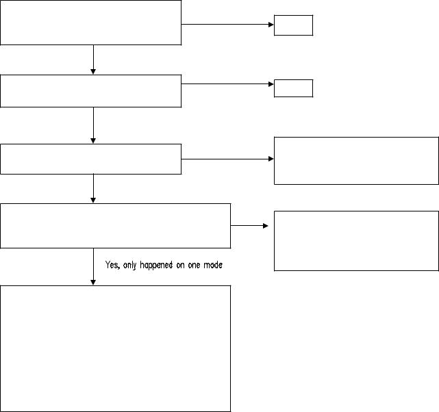
II.ALL SCREEN HAS INTERFERENCES OR NOISE, CAN’T BE FIXED BY AUTO KEY
** NOTE: There is so many kind of interferences, 1). One is cause by some VGA-CARD that not meet VESA spec or power grounding too bad that influence our circuit
2).other is cause by external interferences, move the monitor far from electronic equipment.( rarely happened)
Use DOT-pattern, or win98/99 shut-down
mode pattern, press “AUTO” key, was the OK interferences disappear ??
NG, interferences still exist
OK
Adjust “FOCUS” step by step, until the horizontal interferences disappear
NG
Yes, has extension
Does your signal-cable have an additional cable for extension ??
NO additional extension cable
END
END
Put away the additional cable
May be the additional cable grounding is not quite well
Does your noise only exist in one mode only? (ex: only at 1024x768 @ 75 Hz, other is normal)
That was cause by you VGA-CARD setting, your VGA card timing backporch/frontporch exceed vesa timing too far, for some new AGP-VGA-CARD such situation always happened
So in your control-panel icon ,select monitor ,setting , advance ,screen-adjust,at
Size icon, increase step by step slowly, press “”AUTO” key every step you increase the SIZE . repeat the procedure( increase/decrease SIZE one-step and press AUTO) until the interferences disappear, press “APPLY” to save in your VGA
NO, all mode
Change the Signal-cable to new-one or Try other brand VGA-CARD
(make sure just only that brand VGACARD has this problem ,contact RDtaipei)
17
 Loading...