


SC7000
Table of contents
 Loading...
SC 7000 and SC 9000XL Patient Monitors
Service Manual
E331.E539U.719.10.01.02
ASK-T898-03-7600
EM Guidelines, 1997 -04-02


SC 7000 and SC 9000XL Patient Monitors Service Manual
ASK-T898-02-7600 Siemens Medical Systems, EM-PCS Danvers
apolotmfr5_5.advisory.fm/07-98/kaupp
ADVISORY
Siemens is liable for the safety of its equipment only if maintenance, repair, and modifications are performed
by authorized personnel, and if components affecting the equipment's safety are replaced with Siemens
spare parts.
Any modification or repair not done by Siemens personnel must be documented. Such documentation must:
• be signed and dated
• contain the name of the company performing the work
• describe the changes made
• describe any equipment performance change s.
It is the responsibility of the user to contact Siemens to determine warranty status and/or liabilities if other
than an authorized Siemens technician repairs or makes modifications to medical devices.

Service Manual SC 7000 and SC 9000XL Patient Monitors
Siemens Medical Systems, EM-PCS, Danvers ASK-T898-02-7600
apolotmfr5_5.Advisory.fm/07-98/kaupp

ASK-T898-03-7600 Siemens Medical Systems, EM-PCS Danvers i
7k9kXLSM.book.CD_ROMTOC.fm/04-99/kaupp
NOT A CONTROLLE D DOCUMENT
7DEOH RI &RQWHQWV
ADVISORY
Chapter 1: General Information . . . . . . . . . . . . . . . . . . . . . . . . . . . . . . . . . . . . . . . . . . . . . .1
1 Introduction . . . . . . . . . . . . . . . . . . . . . . . . . . . . . . . . . . . . . . . . . . . . . . . . . . . . . . . . . . . . . . . . 1
2 O v erview . . . . . . . . . . . . . . . . . . . . . . . . . . . . . . . . . . . . . . . . . . . . . . . . . . . . . . . . . . . . . . . . . . 1
2.1 R50 Recorder . . . . . . . . . . . . . . . . . . . . . . . . . . . . . . . . . . . . . . . . . . . . . . . . . . . . . . . . . . . . 1
2.2 Infinity Docking Station . . . . . . . . . . . . . . . . . . . . . . . . . . . . . . . . . . . . . . . . . . . . . . . . . . . 1
2.3 Docking Station (Discontinued) . . . . . . . . . . . . . . . . . . . . . . . . . . . . . . . . . . . . . . . . . . . . 1
2.4 InfinityNet CPS (Discontinued) . . . . . . . . . . . . . . . . . . . . . . . . . . . . . . . . . . . . . . . . . . . . . 2
2.5 Remote Display . . . . . . . . . . . . . . . . . . . . . . . . . . . . . . . . . . . . . . . . . . . . . . . . . . . . . . . . . . 2
2.5.1 Passive Remote Display . . . . . . . . . . . . . . . . . . . . . . . . . . . . . . . . . . . . . . . . . . . . 2
2.5.2 Keypad . . . . . . . . . . . . . . . . . . . . . . . . . . . . . . . . . . . . . . . . . . . . . . . . . . . . . . . . . . 2
2.5.3 SC 9015 (Discontinued) . . . . . . . . . . . . . . . . . . . . . . . . . . . . . . . . . . . . . . . . . . . . . 2
2.6 PSL . . . . . . . . . . . . . . . . . . . . . . . . . . . . . . . . . . . . . . . . . . . . . . . . . . . . . . . . . . . . . . . . . . . . 2
2.7 Interface Plate . . . . . . . . . . . . . . . . . . . . . . . . . . . . . . . . . . . . . . . . . . . . . . . . . . . . . . . . . . . 2
3 S ervice Policy . . . . . . . . . . . . . . . . . . . . . . . . . . . . . . . . . . . . . . . . . . . . . . . . . . . . . . . . . . . . . . 2
4 Related Documentation . . . . . . . . . . . . . . . . . . . . . . . . . . . . . . . . . . . . . . . . . . . . . . . . . . . . . . 3
5 Cleaning . . . . . . . . . . . . . . . . . . . . . . . . . . . . . . . . . . . . . . . . . . . . . . . . . . . . . . . . . . . . . . . . . . 3
6 Te chnical Data . . . . . . . . . . . . . . . . . . . . . . . . . . . . . . . . . . . . . . . . . . . . . . . . . . . . . . . . . . . . . 3
7 Brief Operating Instructions . . . . . . . . . . . . . . . . . . . . . . . . . . . . . . . . . . . . . . . . . . . . . . . . . . 3
7.1 SC 7000 and SC 9000XL Monitor Controls . . . . . . . . . . . . . . . . . . . . . . . . . . . . . . . . . . . . 3
8 P eripheral Device Controls . . . . . . . . . . . . . . . . . . . . . . . . . . . . . . . . . . . . . . . . . . . . . . . . . . . 3
9 P asswords . . . . . . . . . . . . . . . . . . . . . . . . . . . . . . . . . . . . . . . . . . . . . . . . . . . . . . . . . . . . . . . . . 3
9.1 Clinical Password . . . . . . . . . . . . . . . . . . . . . . . . . . . . . . . . . . . . . . . . . . . . . . . . . . . . . . . . 3
9.2 Service Password . . . . . . . . . . . . . . . . . . . . . . . . . . . . . . . . . . . . . . . . . . . . . . . . . . . . . . . . 3
10Menus . . . . . . . . . . . . . . . . . . . . . . . . . . . . . . . . . . . . . . . . . . . . . . . . . . . . . . . . . . . . . . . . . . . . 3
10.1Main Menu . . . . . . . . . . . . . . . . . . . . . . . . . . . . . . . . . . . . . . . . . . . . . . . . . . . . . . . . . . . . . . 3
10.2Service Menu . . . . . . . . . . . . . . . . . . . . . . . . . . . . . . . . . . . . . . . . . . . . . . . . . . . . . . . . . . . 4
10.3Install Monitoring Software . . . . . . . . . . . . . . . . . . . . . . . . . . . . . . . . . . . . . . . . . . . . . . . . 4
10.4Configuration Download Procedure . . . . . . . . . . . . . . . . . . . . . . . . . . . . . . . . . . . . . . . . . 5
10.5Diagnostic Log Upload Procedure . . . . . . . . . . . . . . . . . . . . . . . . . . . . . . . . . . . . . . . . . . 6
Chapter 2: Theory of Operation . . . . . . . . . . . . . . . . . . . . . . . . . . . . . . . . . . . . . . . . . . . . . .7
1 Introduction . . . . . . . . . . . . . . . . . . . . . . . . . . . . . . . . . . . . . . . . . . . . . . . . . . . . . . . . . . . . . . . . 7
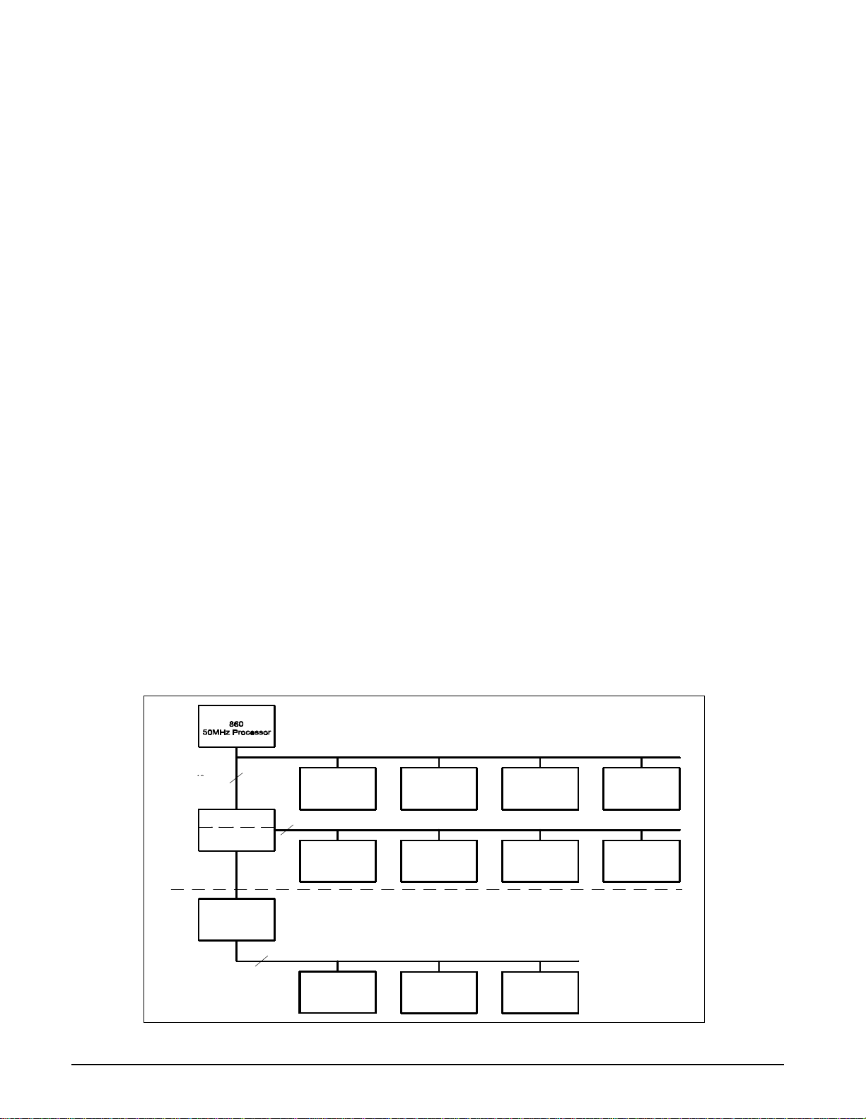
Figure 2-1 SC 7000 / SC 9000XL Bus Structure . . . . . . . . . . . . . . . . . . . . . . . . . . . . . . . . . 7
1.1 Main Processor Bus . . . . . . . . . . . . . . . . . . . . . . . . . . . . . . . . . . . . . . . . . . . . . . . . . . . . . . 8
1.2 Front End Bus . . . . . . . . . . . . . . . . . . . . . . . . . . . . . . . . . . . . . . . . . . . . . . . . . . . . . . . . . . . 8

Service Manual SC 7000 and SC 9000XL Patient Monitors
ii Siemens Medical Systems, EM-PCS, Danvers ASK-T898-03-7600
NOT A CONTROLLE D DOCUMENT
7k9kXLSM.book.CD_ROMTOC . fm/0 4-99/k aupp
1.3 REMOTE COMM Bus . . . . . . . . . . . . . . . . . . . . . . . . . . . . . . . . . . . . . . . . . . . . . . . . . . . . . 8
Figure 2-2 REMOTE COMM Bus . . . . . . . . . . . . . . . . . . . . . . . . . . . . . . . . . . . . . . . . . . . . . 8
1.4 Error Handling . . . . . . . . . . . . . . . . . . . . . . . . . . . . . . . . . . . . . . . . . . . . . . . . . . . . . . . . . . . 9
2 Main Unit . . . . . . . . . . . . . . . . . . . . . . . . . . . . . . . . . . . . . . . . . . . . . . . . . . . . . . . . . . . . . . . . . . 9
Figure 2-3 SC 7000 / SC 9000XL Block Diagram . . . . . . . . . . . . . . . . . . . . . . . . . . . . . . . . 9
2.1 Front Bezel Board . . . . . . . . . . . . . . . . . . . . . . . . . . . . . . . . . . . . . . . . . . . . . . . . . . . . . . . 10
2.2 Cooling System . . . . . . . . . . . . . . . . . . . . . . . . . . . . . . . . . . . . . . . . . . . . . . . . . . . . . . . . . 10
2.3 Real Time Clock . . . . . . . . . . . . . . . . . . . . . . . . . . . . . . . . . . . . . . . . . . . . . . . . . . . . . . . . 10
2.4 Non-volatile Memory Battery Backup and Power Reset . . . . . . . . . . . . . . . . . . . . . . . . 10
2.5 MPC 860 Communication Channels . . . . . . . . . . . . . . . . . . . . . . . . . . . . . . . . . . . . . . . . 11
2.6 Device CPS . . . . . . . . . . . . . . . . . . . . . . . . . . . . . . . . . . . . . . . . . . . . . . . . . . . . . . . . . . . . 11
2.7 Infinity Docking Station . . . . . . . . . . . . . . . . . . . . . . . . . . . . . . . . . . . . . . . . . . . . . . . . . . 11
2.8 etCO2 cartridge . . . . . . . . . . . . . . . . . . . . . . . . . . . . . . . . . . . . . . . . . . . . . . . . . . . . . . . . . 11
2.9 External Battery . . . . . . . . . . . . . . . . . . . . . . . . . . . . . . . . . . . . . . . . . . . . . . . . . . . . . . . . 11
2.10Interfaces . . . . . . . . . . . . . . . . . . . . . . . . . . . . . . . . . . . . . . . . . . . . . . . . . . . . . . . . . . . . . 11
2.10.1 Local Fixed Keys Interface . . . . . . . . . . . . . . . . . . . . . . . . . . . . . . . . . . . . . . . . . 11
2.10.2 Local Rotary Knob Interface . . . . . . . . . . . . . . . . . . . . . . . . . . . . . . . . . . . . . . . . 11
2.10.3 SC 9015 Interface . . . . . . . . . . . . . . . . . . . . . . . . . . . . . . . . . . . . . . . . . . . . . . . . . 12
2.10.4 Fast Analog Output . . . . . . . . . . . . . . . . . . . . . . . . . . . . . . . . . . . . . . . . . . . . . . . 12
2.10.5 HiFi Audible Alarm Interface . . . . . . . . . . . . . . . . . . . . . . . . . . . . . . . . . . . . . . . . 12
2.10.6 LED/Statu s Interface . . . . . . . . . . . . . . . . . . . . . . . . . . . . . . . . . . . . . . . . . . . . . . 12
2.10.7 QRS Sync Out Interface . . . . . . . . . . . . . . . . . . . . . . . . . . . . . . . . . . . . . . . . . . . 12
2.10.8 Local Alarm Out Interface . . . . . . . . . . . . . . . . . . . . . . . . . . . . . . . . . . . . . . . . . . 12
2.10.9 Remote Alarm Out Interface for Nurse Call . . . . . . . . . . . . . . . . . . . . . . . . . . . . 12
2.11Recorder Interface . . . . . . . . . . . . . . . . . . . . . . . . . . . . . . . . . . . . . . . . . . . . . . . . . . . . . . 13
2.12Backlight Control . . . . . . . . . . . . . . . . . . . . . . . . . . . . . . . . . . . . . . . . . . . . . . . . . . . . . . . 13
2.13Serial EEPROMS . . . . . . . . . . . . . . . . . . . . . . . . . . . . . . . . . . . . . . . . . . . . . . . . . . . . . . . . 13
3 G raphics Subsystem . . . . . . . . . . . . . . . . . . . . . . . . . . . . . . . . . . . . . . . . . . . . . . . . . . . . . . . 13
Figure 2-4 Graphics Subsystem . . . . . . . . . . . . . . . . . . . . . . . . . . . . . . . . . . . . . . . . . . . . 13
3.1 Overview . . . . . . . . . . . . . . . . . . . . . . . . . . . . . . . . . . . . . . . . . . . . . . . . . . . . . . . . . . . . . . 13
3.2 Functional Description . . . . . . . . . . . . . . . . . . . . . . . . . . . . . . . . . . . . . . . . . . . . . . . . . . . 13
3.3 Video Output . . . . . . . . . . . . . . . . . . . . . . . . . . . . . . . . . . . . . . . . . . . . . . . . . . . . . . . . . . . 14
4 DSP Subsystem . . . . . . . . . . . . . . . . . . . . . . . . . . . . . . . . . . . . . . . . . . . . . . . . . . . . . . . . . . . 14
Figure 2-5 DSP Subsystem . . . . . . . . . . . . . . . . . . . . . . . . . . . . . . . . . . . . . . . . . . . . . . . . 14
5 P O D COM Subsystem . . . . . . . . . . . . . . . . . . . . . . . . . . . . . . . . . . . . . . . . . . . . . . . . . . . . . . 15
Figure 2-6 POD Communications . . . . . . . . . . . . . . . . . . . . . . . . . . . . . . . . . . . . . . . . . . . 15

SC 7000 and SC 9000XL Patient Monitors Service Manual
ASK-T898-03-7600 Siemens Medical Systems, EM-PCS Danvers iii
7k9kXLSM.book.CD_ROMTOC.fm/04-99/kaupp
NOT A CONTROLLE D DOCUMENT
5.1 Overview . . . . . . . . . . . . . . . . . . . . . . . . . . . . . . . . . . . . . . . . . . . . . . . . . . . . . . . . . . . . . . 15
5.2 Outputs . . . . . . . . . . . . . . . . . . . . . . . . . . . . . . . . . . . . . . . . . . . . . . . . . . . . . . . . . . . . . . . 16
5.3 Error Handling . . . . . . . . . . . . . . . . . . . . . . . . . . . . . . . . . . . . . . . . . . . . . . . . . . . . . . . . . . 16
6 P ow er Conversion . . . . . . . . . . . . . . . . . . . . . . . . . . . . . . . . . . . . . . . . . . . . . . . . . . . . . . . . . 16
Figure 2-7 Power Conversion . . . . . . . . . . . . . . . . . . . . . . . . . . . . . . . . . . . . . . . . . . . . . . 16
6.1 Power Control . . . . . . . . . . . . . . . . . . . . . . . . . . . . . . . . . . . . . . . . . . . . . . . . . . . . . . . . . . 16
6.1.1 Power Buss . . . . . . . . . . . . . . . . . . . . . . . . . . . . . . . . . . . . . . . . . . . . . . . . . . . . . 16
6.1.2 Control and Load Sequencing . . . . . . . . . . . . . . . . . . . . . . . . . . . . . . . . . . . . . . 16
6.1.3 Power On / Off . . . . . . . . . . . . . . . . . . . . . . . . . . . . . . . . . . . . . . . . . . . . . . . . . . . 17
6.1.4 Power Source Control . . . . . . . . . . . . . . . . . . . . . . . . . . . . . . . . . . . . . . . . . . . . . 17
6.1.5 Battery charging . . . . . . . . . . . . . . . . . . . . . . . . . . . . . . . . . . . . . . . . . . . . . . . . . 17
6.1.6 Indicator LEDs . . . . . . . . . . . . . . . . . . . . . . . . . . . . . . . . . . . . . . . . . . . . . . . . . . . 17
Table 2-1Power and Charger LED Indicators . . . . . . . . . . . . . . . . . . . . . . . . . . . . . . . . 17
6.1.7 Power Mode Indication . . . . . . . . . . . . . . . . . . . . . . . . . . . . . . . . . . . . . . . . . . . . 18
Table 2-2 Power Mode Table . . . . . . . . . . . . . . . . . . . . . . . . . . . . . . . . . . . . . . . . . . . . . 18
6.1.8 Piezo Alarm . . . . . . . . . . . . . . . . . . . . . . . . . . . . . . . . . . . . . . . . . . . . . . . . . . . . . 18
Table 2-3Piezo Alarm . . . . . . . . . . . . . . . . . . . . . . . . . . . . . . . . . . . . . . . . . . . . . . . . . . . 18
6.1.9 Fault Protection . . . . . . . . . . . . . . . . . . . . . . . . . . . . . . . . . . . . . . . . . . . . . . . . . . 18
6.1.10 External Pod and Cartridge Overload Protection . . . . . . . . . . . . . . . . . . . . . . . 18
6.2 Electrical Specifications . . . . . . . . . . . . . . . . . . . . . . . . . . . . . . . . . . . . . . . . . . . . . . . . . . 19
6.2.1 Power Supply Input . . . . . . . . . . . . . . . . . . . . . . . . . . . . . . . . . . . . . . . . . . . . . . . 19
6.3 System Power Specifications . . . . . . . . . . . . . . . . . . . . . . . . . . . . . . . . . . . . . . . . . . . . . 19
6.3.1 Maximum Power Summary . . . . . . . . . . . . . . . . . . . . . . . . . . . . . . . . . . . . . . . . . 19
6.3.2 Main Battery Specifications . . . . . . . . . . . . . . . . . . . . . . . . . . . . . . . . . . . . . . . . 19
6.3.3 External Battery Specifications . . . . . . . . . . . . . . . . . . . . . . . . . . . . . . . . . . . . . 19
7 Front Bezel Board . . . . . . . . . . . . . . . . . . . . . . . . . . . . . . . . . . . . . . . . . . . . . . . . . . . . . . . . . . 19
7.1 Introduction . . . . . . . . . . . . . . . . . . . . . . . . . . . . . . . . . . . . . . . . . . . . . . . . . . . . . . . . . . . . 19
7.2 Functional Description . . . . . . . . . . . . . . . . . . . . . . . . . . . . . . . . . . . . . . . . . . . . . . . . . . . 19
7.3 LCD Backlight Invertor Interface . . . . . . . . . . . . . . . . . . . . . . . . . . . . . . . . . . . . . . . . . . . 20
7.4 Ambient Light Interface . . . . . . . . . . . . . . . . . . . . . . . . . . . . . . . . . . . . . . . . . . . . . . . . . . 20
7.5 Local Rotary Knob/fixed Keys Interface . . . . . . . . . . . . . . . . . . . . . . . . . . . . . . . . . . . . . 20
7.6 Battery/power LED Interface . . . . . . . . . . . . . . . . . . . . . . . . . . . . . . . . . . . . . . . . . . . . . . 20
8 MultiMed Front End . . . . . . . . . . . . . . . . . . . . . . . . . . . . . . . . . . . . . . . . . . . . . . . . . . . . . . . . 20
8.1 Introduction . . . . . . . . . . . . . . . . . . . . . . . . . . . . . . . . . . . . . . . . . . . . . . . . . . . . . . . . . . . . 20
8.2 Safety . . . . . . . . . . . . . . . . . . . . . . . . . . . . . . . . . . . . . . . . . . . . . . . . . . . . . . . . . . . . . . . . . 20
Figure 2-8 MultiMed Front End . . . . . . . . . . . . . . . . . . . . . . . . . . . . . . . . . . . . . . . . . . . . . 21

Service Manual SC 7000 and SC 9000XL Patient Monitors
iv Siemens Medical Systems, EM-PCS, Danvers ASK-T898-03-7600
NOT A CONTROLLE D DOCUMENT
7k9kXLSM.book.CD_ROMTOC . fm/0 4-99/k aupp
8.3 Functional Description . . . . . . . . . . . . . . . . . . . . . . . . . . . . . . . . . . . . . . . . . . . . . . . . . . . 21
8.3.1 ECG/Resp . . . . . . . . . . . . . . . . . . . . . . . . . . . . . . . . . . . . . . . . . . . . . . . . . . . . . . . 21
Table 2-4Parameter Sampling Table . . . . . . . . . . . . . . . . . . . . . . . . . . . . . . . . . . . . . . . 22
Figure 2-9 Lead Forming Network . . . . . . . . . . . . . . . . . . . . . . . . . . . . . . . . . . . . . . . . . . 23
Figure 2-10 Respiration Functional Block Diagram . . . . . . . . . . . . . . . . . . . . . . . . . . . . . 24
8.3.2 Temperature . . . . . . . . . . . . . . . . . . . . . . . . . . . . . . . . . . . . . . . . . . . . . . . . . . . . . 24
Figure 2-11 Temperature Functional Block Diagram . . . . . . . . . . . . . . . . . . . . . . . . . . . . 24
8.3.3 SpO2 . . . . . . . . . . . . . . . . . . . . . . . . . . . . . . . . . . . . . . . . . . . . . . . . . . . . . . . . . . . 25
Figure 2-12 SpO2 Functional Block Diagram . . . . . . . . . . . . . . . . . . . . . . . . . . . . . . . . . . 25
9 NBP . . . . . . . . . . . . . . . . . . . . . . . . . . . . . . . . . . . . . . . . . . . . . . . . . . . . . . . . . . . . . . . . . . . . . 26
Figure 2-13 NBP Functional Block Diagram . . . . . . . . . . . . . . . . . . . . . . . . . . . . . . . . . . . 26
9.1 Introduction . . . . . . . . . . . . . . . . . . . . . . . . . . . . . . . . . . . . . . . . . . . . . . . . . . . . . . . . . . . . 26
9.2 Pneumatic Subassembly . . . . . . . . . . . . . . . . . . . . . . . . . . . . . . . . . . . . . . . . . . . . . . . . . 26
9.3 Transducers . . . . . . . . . . . . . . . . . . . . . . . . . . . . . . . . . . . . . . . . . . . . . . . . . . . . . . . . . . . 27
9.4 Pneumatic Controls . . . . . . . . . . . . . . . . . . . . . . . . . . . . . . . . . . . . . . . . . . . . . . . . . . . . . 27
9.5 Safety timer . . . . . . . . . . . . . . . . . . . . . . . . . . . . . . . . . . . . . . . . . . . . . . . . . . . . . . . . . . . . 27
9.6 Logic gate array . . . . . . . . . . . . . . . . . . . . . . . . . . . . . . . . . . . . . . . . . . . . . . . . . . . . . . . . 27
9.7 Non-volatile memory . . . . . . . . . . . . . . . . . . . . . . . . . . . . . . . . . . . . . . . . . . . . . . . . . . . . 28
9.8 Hose detection . . . . . . . . . . . . . . . . . . . . . . . . . . . . . . . . . . . . . . . . . . . . . . . . . . . . . . . . . 28
9.9 Watchdog Timer . . . . . . . . . . . . . . . . . . . . . . . . . . . . . . . . . . . . . . . . . . . . . . . . . . . . . . . . 28
10HemoMed Front End . . . . . . . . . . . . . . . . . . . . . . . . . . . . . . . . . . . . . . . . . . . . . . . . . . . . . . . 28
Figure 2-14 HemoMed Front End . . . . . . . . . . . . . . . . . . . . . . . . . . . . . . . . . . . . . . . . . . . . 28
10.1Introduction . . . . . . . . . . . . . . . . . . . . . . . . . . . . . . . . . . . . . . . . . . . . . . . . . . . . . . . . . . . 28
10.2Pressure . . . . . . . . . . . . . . . . . . . . . . . . . . . . . . . . . . . . . . . . . . . . . . . . . . . . . . . . . . . . . . 28
10.3Cardiac Output . . . . . . . . . . . . . . . . . . . . . . . . . . . . . . . . . . . . . . . . . . . . . . . . . . . . . . . . . 29
11etCO2 Module . . . . . . . . . . . . . . . . . . . . . . . . . . . . . . . . . . . . . . . . . . . . . . . . . . . . . . . . . . . . . 29
Figure 2-15 etCO2 Sensing Process Functional Block Diagram . . . . . . . . . . . . . . . . . . . 29
11.1System Hardware . . . . . . . . . . . . . . . . . . . . . . . . . . . . . . . . . . . . . . . . . . . . . . . . . . . . . . . 3 0
11.2System Memory . . . . . . . . . . . . . . . . . . . . . . . . . . . . . . . . . . . . . . . . . . . . . . . . . . . . . . . . 30
11.3User Interface . . . . . . . . . . . . . . . . . . . . . . . . . . . . . . . . . . . . . . . . . . . . . . . . . . . . . . . . . . 30
12HEMO 2/4 POD . . . . . . . . . . . . . . . . . . . . . . . . . . . . . . . . . . . . . . . . . . . . . . . . . . . . . . . . . . . . 30
12.1Functional Description . . . . . . . . . . . . . . . . . . . . . . . . . . . . . . . . . . . . . . . . . . . . . . . . . . 30
12.2Pressure . . . . . . . . . . . . . . . . . . . . . . . . . . . . . . . . . . . . . . . . . . . . . . . . . . . . . . . . . . . . . . 30
Figure 2-16 HEMO 2/4 POD Functional Block Diagram . . . . . . . . . . . . . . . . . . . . . . . . . . 31
Figure 2-17 IBP Functional Block Diagram . . . . . . . . . . . . . . . . . . . . . . . . . . . . . . . . . . . . 31
12.2.1 Temperature . . . . . . . . . . . . . . . . . . . . . . . . . . . . . . . . . . . . . . . . . . . . . . . . . . . . . 31
12.2.2 Cardiac Output . . . . . . . . . . . . . . . . . . . . . . . . . . . . . . . . . . . . . . . . . . . . . . . . . . . 32

SC 7000 and SC 9000XL Patient Monitors Service Manual
ASK-T898-03-7600 Siemens Medical Systems, EM-PCS Danvers v
7k9kXLSM.book.CD_ROMTOC.fm/04-99/kaupp
NOT A CONTROLLE D DOCUMENT
12.2.3 EEPROM Storage . . . . . . . . . . . . . . . . . . . . . . . . . . . . . . . . . . . . . . . . . . . . . . . . .32
12.2.4 LCD and Push Buttons . . . . . . . . . . . . . . . . . . . . . . . . . . . . . . . . . . . . . . . . . . . . .32
12.2.5 Current Limiting the Voltage Reference . . . . . . . . . . . . . . . . . . . . . . . . . . . . . . .32
13Remote Comm Subsystem Hardware . . . . . . . . . . . . . . . . . . . . . . . . . . . . . . . . . . . . . . . . . . 32
13.1Connection Characteristics . . . . . . . . . . . . . . . . . . . . . . . . . . . . . . . . . . . . . . . . . . . . . . . 32
14Infinity Network CPS and IDS (w/ Power Supply) . . . . . . . . . . . . . . . . . . . . . . . . . . . . . . . .33
14.1Network Board Hardware . . . . . . . . . . . . . . . . . . . . . . . . . . . . . . . . . . . . . . . . . . . . . . . . .33
Figure 2-18 Comm unications Functional Block Diagram . . . . . . . . . . . . . . . . . . . . . . . . . 33
14.2EEPROMs . . . . . . . . . . . . . . . . . . . . . . . . . . . . . . . . . . . . . . . . . . . . . . . . . . . . . . . . . . . . . .34
14.3CPS Power Supply . . . . . . . . . . . . . . . . . . . . . . . . . . . . . . . . . . . . . . . . . . . . . . . . . . . . . .34
15Infinity Docking Station (IDS) . . . . . . . . . . . . . . . . . . . . . . . . . . . . . . . . . . . . . . . . . . . . . . . . . 35
Chapter 3: Repair . . . . . . . . . . . . . . . . . . . . . . . . . . . . . . . . . . . . . . . . . . . . . . . . . . . . . . . . 37
1 Introduction . . . . . . . . . . . . . . . . . . . . . . . . . . . . . . . . . . . . . . . . . . . . . . . . . . . . . . . . . . . . . . .37
2 Service Policy and Replaceable Parts . . . . . . . . . . . . . . . . . . . . . . . . . . . . . . . . . . . . . . . . . .37
2.1 Base Unit . . . . . . . . . . . . . . . . . . . . . . . . . . . . . . . . . . . . . . . . . . . . . . . . . . . . . . . . . . . . . .37
2.2 R50 Recorder . . . . . . . . . . . . . . . . . . . . . . . . . . . . . . . . . . . . . . . . . . . . . . . . . . . . . . . . . . .37
2.3 Modules, PODs, and Peripherals . . . . . . . . . . . . . . . . . . . . . . . . . . . . . . . . . . . . . . . . . . . 38
3 Safety Precautions . . . . . . . . . . . . . . . . . . . . . . . . . . . . . . . . . . . . . . . . . . . . . . . . . . . . . . . . . 38
4 Replaceable Parts and Subassemblies That DO NOT Require Opening the Monitor . . . .38
4.1 Replacing Rotary Knob . . . . . . . . . . . . . . . . . . . . . . . . . . . . . . . . . . . . . . . . . . . . . . . . . . .38
4.2 Replacing Front Bezel Labels . . . . . . . . . . . . . . . . . . . . . . . . . . . . . . . . . . . . . . . . . . . . . .38
4.2.1 Removing Existing Label . . . . . . . . . . . . . . . . . . . . . . . . . . . . . . . . . . . . . . . . . . . 39
4.2.2 Installing Language Label . . . . . . . . . . . . . . . . . . . . . . . . . . . . . . . . . . . . . . . . . .39
4.2.3 Installing SIEMENS Metal Logo Label . . . . . . . . . . . . . . . . . . . . . . . . . . . . . . . . .39
4.2.4 Installing Monitor Model Label . . . . . . . . . . . . . . . . . . . . . . . . . . . . . . . . . . . . . .39
4.3 Replacing Foot Pads . . . . . . . . . . . . . . . . . . . . . . . . . . . . . . . . . . . . . . . . . . . . . . . . . . . . .39
4.4 Removing / Installing External Battery and Support Components . . . . . . . . . . . . . . . . 39
4.4.1 External Battery (optional) . . . . . . . . . . . . . . . . . . . . . . . . . . . . . . . . . . . . . . . . . .39
Figure 3-1 SC 7000 and SC 9000XL Rear View w/ Cover Removed . . . . . . . . . . . . . . . .40
Figure 3-2 Rear Housing Components/Subassemblies . . . . . . . . . . . . . . . . . . . . . . . . . .40
4.4.2 External Battery Compartment Door . . . . . . . . . . . . . . . . . . . . . . . . . . . . . . . . . .41
4.4.3 Replacing External Battery Ejection Spring . . . . . . . . . . . . . . . . . . . . . . . . . . . .41
4.5 Removing / Installing Main Battery . . . . . . . . . . . . . . . . . . . . . . . . . . . . . . . . . . . . . . . . .41
Figure 3-3 Battery Cable Ties . . . . . . . . . . . . . . . . . . . . . . . . . . . . . . . . . . . . . . . . . . . . . . .42
4.6 Replacing Power Cable and Speaker Subassembly . . . . . . . . . . . . . . . . . . . . . . . . . . . .42

Service Manual SC 7000 and SC 9000XL Patient Monitors
vi Siemens Medical Systems, EM-PCS, Danvers ASK-T898-03-7600
NOT A CONTROLLE D DOCUMENT
7k9kXLSM.book.CD_ROMTOC . fm/0 4-99/k aupp
4.7 NP Filters and Pump Subassembly . . . . . . . . . . . . . . . . . . . . . . . . . . . . . . . . . . . . . . . . . 43
Figure 3-4 NP Subassembly in Rear Housing . . . . . . . . . . . . . . . . . . . . . . . . . . . . . . . . . 43
4.7.1 Replacing Manifold and Air Intake Filters . . . . . . . . . . . . . . . . . . . . . . . . . . . . . 43
4.7.2 Removing NP Subassembly . . . . . . . . . . . . . . . . . . . . . . . . . . . . . . . . . . . . . . . . 43
4.7.3 Installing NP Subassembly . . . . . . . . . . . . . . . . . . . . . . . . . . . . . . . . . . . . . . . . . 44
4.7.4 NBP Characterization Preparation . . . . . . . . . . . . . . . . . . . . . . . . . . . . . . . . . . . 44
4.7.5 NBP Characterization . . . . . . . . . . . . . . . . . . . . . . . . . . . . . . . . . . . . . . . . . . . . . 45
4.8 Replacing Monitor Handle . . . . . . . . . . . . . . . . . . . . . . . . . . . . . . . . . . . . . . . . . . . . . . . . 45
5 O pe ning Monitor . . . . . . . . . . . . . . . . . . . . . . . . . . . . . . . . . . . . . . . . . . . . . . . . . . . . . . . . . . . 45
5.1 Removing/Installing Side-Panels . . . . . . . . . . . . . . . . . . . . . . . . . . . . . . . . . . . . . . . . . . 45
5.1.1 Removing Ejection Shaft Cover . . . . . . . . . . . . . . . . . . . . . . . . . . . . . . . . . . . . . 45
5.1.2 Installing Ejection Shaft Cover . . . . . . . . . . . . . . . . . . . . . . . . . . . . . . . . . . . . . . 46
Figure 3-5 Removing Left and Right Side Panels . . . . . . . . . . . . . . . . . . . . . . . . . . . . . . 46
5.1.3 Removing Right Side Panel . . . . . . . . . . . . . . . . . . . . . . . . . . . . . . . . . . . . . . . . 46
5.1.4 Installing Right Side Panel . . . . . . . . . . . . . . . . . . . . . . . . . . . . . . . . . . . . . . . . . 46
5.1.5 Removing Left Side Panel . . . . . . . . . . . . . . . . . . . . . . . . . . . . . . . . . . . . . . . . . . 46
5.1.6 Installing Left Side Panel . . . . . . . . . . . . . . . . . . . . . . . . . . . . . . . . . . . . . . . . . . 47
5.2 Separating Front Bezel Subassembly and Rear Housing Subassembly . . . . . . . . . . . 47
Figure 3-6 Bottom Release Tabs for Front Bezel Subassembly . . . . . . . . . . . . . . . . . . 47
Figure 3-7 Security Clip
0
0
and Tape
@
@
. . . . . . . . . . . . . . . . . . . . . . . . . . . . . . . . . . . . . . 47
Figure 3-8 Top Release Tabs for Front Bezel Subassembly . . . . . . . . . . . . . . . . . . . . . 48
6 Replacing Subassemblies in Rear Housing . . . . . . . . . . . . . . . . . . . . . . . . . . . . . . . . . . . . . 48
6.1 Removing/Installing Funnel . . . . . . . . . . . . . . . . . . . . . . . . . . . . . . . . . . . . . . . . . . . . . . . 48
6.2 Main Processor PCB Subassembly . . . . . . . . . . . . . . . . . . . . . . . . . . . . . . . . . . . . . . . . 48
6.2.1 Removing Main Processor PCB Subassembly . . . . . . . . . . . . . . . . . . . . . . . . . 49
6.2.2 Installing Main Processor PCB Subassembly . . . . . . . . . . . . . . . . . . . . . . . . . . 49
6.3 Replacing Rear Housing . . . . . . . . . . . . . . . . . . . . . . . . . . . . . . . . . . . . . . . . . . . . . . . . . 49
Figure 3-9 Main Subassemblies of SC 7000 and SC 9000XL Patient Monitors . . . . . . 50
Figure 3-10 Front Bezel Subassembly Components . . . . . . . . . . . . . . . . . . . . . . . . . . . . 51
Figure 3-11 Front Bezel Subassembly - Interior View . . . . . . . . . . . . . . . . . . . . . . . . . . . . 51
7 Replacing Subassemblies in Front Bezel Subassembly . . . . . . . . . . . . . . . . . . . . . . . . . . 52
7.1 Front Bezel PC Board . . . . . . . . . . . . . . . . . . . . . . . . . . . . . . . . . . . . . . . . . . . . . . . . . . . . 52
7.1.1 Removing Front Bezel PCB . . . . . . . . . . . . . . . . . . . . . . . . . . . . . . . . . . . . . . . . 52
Figure 3-12 Optical Encoder Subassembly. See Note in Figure 3-10 caption. . . . . . . . . 52
7.1.2 Installing Front Bezel PC Board . . . . . . . . . . . . . . . . . . . . . . . . . . . . . . . . . . . . . 53
7.2 Optical Encoder Subassembly . . . . . . . . . . . . . . . . . . . . . . . . . . . . . . . . . . . . . . . . . . . . 54

SC 7000 and SC 9000XL Patient Monitors Service Manual
ASK-T898-03-7600 Siemens Medical Systems, EM-PCS Danvers vii
7k9kXLSM.book.CD_ROMTOC.fm/04-99/kaupp
NOT A CONTROLLE D DOCUMENT
Figure 3-13 Display Screen Subassembly . . . . . . . . . . . . . . . . . . . . . . . . . . . . . . . . . . . . . 54
7.3 Backlight Lamps . . . . . . . . . . . . . . . . . . . . . . . . . . . . . . . . . . . . . . . . . . . . . . . . . . . . . . . . 55
7.4 Front Bezel/Lens Subassembly . . . . . . . . . . . . . . . . . . . . . . . . . . . . . . . . . . . . . . . . . . . . 55
7.5 Front Bezel Subassembly . . . . . . . . . . . . . . . . . . . . . . . . . . . . . . . . . . . . . . . . . . . . . . . . 55
8 Closing Monitor . . . . . . . . . . . . . . . . . . . . . . . . . . . . . . . . . . . . . . . . . . . . . . . . . . . . . . . . . . . 55
Figure 3-14 SC 7000 / SC 9000XL Patient Monitor Bottom View . . . . . . . . . . . . . . . . . . . 56
Figure 3-15 Installing Security Clip and Tape . . . . . . . . . . . . . . . . . . . . . . . . . . . . . . . . . . 56
Chapter 4: Functional Verification and Calibration . . . . . . . . . . . . . . . . . . . . . . . . . . . . .57
1 Introduction . . . . . . . . . . . . . . . . . . . . . . . . . . . . . . . . . . . . . . . . . . . . . . . . . . . . . . . . . . . . . . . 57
2 Recommended Tools and Test Equipment . . . . . . . . . . . . . . . . . . . . . . . . . . . . . . . . . . . . . 57
Table 4-1Recommended Tools and Test Equipment . . . . . . . . . . . . . . . . . . . . . . . . . . 58
3 P ow er Circuits and Start-up . . . . . . . . . . . . . . . . . . . . . . . . . . . . . . . . . . . . . . . . . . . . . . . . . 59
3.1 Power ON/OFF . . . . . . . . . . . . . . . . . . . . . . . . . . . . . . . . . . . . . . . . . . . . . . . . . . . . . . . . . . 59
3.2 Power-Up Sequence . . . . . . . . . . . . . . . . . . . . . . . . . . . . . . . . . . . . . . . . . . . . . . . . . . . . . 59
3.3 Monitor Powered From External Source . . . . . . . . . . . . . . . . . . . . . . . . . . . . . . . . . . . . 59
4 Rotary Knob . . . . . . . . . . . . . . . . . . . . . . . . . . . . . . . . . . . . . . . . . . . . . . . . . . . . . . . . . . . . . . 59
5 LCD Display . . . . . . . . . . . . . . . . . . . . . . . . . . . . . . . . . . . . . . . . . . . . . . . . . . . . . . . . . . . . . . 59
6 Fix ed Keys . . . . . . . . . . . . . . . . . . . . . . . . . . . . . . . . . . . . . . . . . . . . . . . . . . . . . . . . . . . . . . . . 60
6.1 ON/OFF Key . . . . . . . . . . . . . . . . . . . . . . . . . . . . . . . . . . . . . . . . . . . . . . . . . . . . . . . . . . . . 60
6.2 Main Screen Key . . . . . . . . . . . . . . . . . . . . . . . . . . . . . . . . . . . . . . . . . . . . . . . . . . . . . . . . 60
6.3 Alarm Silence Key . . . . . . . . . . . . . . . . . . . . . . . . . . . . . . . . . . . . . . . . . . . . . . . . . . . . . . . 60
6.4 Alarm Limits Key . . . . . . . . . . . . . . . . . . . . . . . . . . . . . . . . . . . . . . . . . . . . . . . . . . . . . . . . 60
6.5 All Alarms Off Key . . . . . . . . . . . . . . . . . . . . . . . . . . . . . . . . . . . . . . . . . . . . . . . . . . . . . . 60
6.6 Code Key . . . . . . . . . . . . . . . . . . . . . . . . . . . . . . . . . . . . . . . . . . . . . . . . . . . . . . . . . . . . . . 60
6.7 Record Key . . . . . . . . . . . . . . . . . . . . . . . . . . . . . . . . . . . . . . . . . . . . . . . . . . . . . . . . . . . . 61
6.8 Print Screen Key . . . . . . . . . . . . . . . . . . . . . . . . . . . . . . . . . . . . . . . . . . . . . . . . . . . . . . . . 61
6.9 NBP Start/Stop Key . . . . . . . . . . . . . . . . . . . . . . . . . . . . . . . . . . . . . . . . . . . . . . . . . . . . . . 61
6.10Zoom Key . . . . . . . . . . . . . . . . . . . . . . . . . . . . . . . . . . . . . . . . . . . . . . . . . . . . . . . . . . . . . 61
6.11Help Key . . . . . . . . . . . . . . . . . . . . . . . . . . . . . . . . . . . . . . . . . . . . . . . . . . . . . . . . . . . . . . 61
6.12Mark Key . . . . . . . . . . . . . . . . . . . . . . . . . . . . . . . . . . . . . . . . . . . . . . . . . . . . . . . . . . . . . . 61
7 E CG /RESP Functions . . . . . . . . . . . . . . . . . . . . . . . . . . . . . . . . . . . . . . . . . . . . . . . . . . . . . . . 6 1
7.1 ECG/RESP Test Setup . . . . . . . . . . . . . . . . . . . . . . . . . . . . . . . . . . . . . . . . . . . . . . . . . . . 61
7.2 Waveforms/Digital Readouts/Tones . . . . . . . . . . . . . . . . . . . . . . . . . . . . . . . . . . . . . . . . 62
7.3 Pacer Detection . . . . . . . . . . . . . . . . . . . . . . . . . . . . . . . . . . . . . . . . . . . . . . . . . . . . . . . . . 62
7.4 Lead-Off Indicators . . . . . . . . . . . . . . . . . . . . . . . . . . . . . . . . . . . . . . . . . . . . . . . . . . . . . . 62
7.5 Alarm Function . . . . . . . . . . . . . . . . . . . . . . . . . . . . . . . . . . . . . . . . . . . . . . . . . . . . . . . . . 62
7.6 Asystole . . . . . . . . . . . . . . . . . . . . . . . . . . . . . . . . . . . . . . . . . . . . . . . . . . . . . . . . . . . . . . . 63

Service Manual SC 7000 and SC 9000XL Patient Monitors
viii Siemens Medical Systems, EM-PCS, Danvers ASK-T898-03-7600
NOT A CONTROLLE D DOCUMENT
7k9kXLSM.book.CD_ROMTOC . fm/0 4-99/k aupp
8 S pO 2 Function . . . . . . . . . . . . . . . . . . . . . . . . . . . . . . . . . . . . . . . . . . . . . . . . . . . . . . . . . . . . 63
8.1 SpO2 Test Setup . . . . . . . . . . . . . . . . . . . . . . . . . . . . . . . . . . . . . . . . . . . . . . . . . . . . . . . . 63
8.2 Waveforms/Digital Readouts/Tones . . . . . . . . . . . . . . . . . . . . . . . . . . . . . . . . . . . . . . . . 63
8.3 Pulse Tone Generator . . . . . . . . . . . . . . . . . . . . . . . . . . . . . . . . . . . . . . . . . . . . . . . . . . . . 63
8.4 SpO2 Limits Alarms . . . . . . . . . . . . . . . . . . . . . . . . . . . . . . . . . . . . . . . . . . . . . . . . . . . . . 64
9 Te m perature Function . . . . . . . . . . . . . . . . . . . . . . . . . . . . . . . . . . . . . . . . . . . . . . . . . . . . . . 64
9.1 Temperature Test Setup . . . . . . . . . . . . . . . . . . . . . . . . . . . . . . . . . . . . . . . . . . . . . . . . . . 64
9.2 Digital Readout . . . . . . . . . . . . . . . . . . . . . . . . . . . . . . . . . . . . . . . . . . . . . . . . . . . . . . . . . 64
9.3 Temperature Calibration Check . . . . . . . . . . . . . . . . . . . . . . . . . . . . . . . . . . . . . . . . . . . . 64
Table 4-2Resistance Value vs Temperature . . . . . . . . . . . . . . . . . . . . . . . . . . . . . . . . . 64
9.3.1 Recommended Equipment . . . . . . . . . . . . . . . . . . . . . . . . . . . . . . . . . . . . . . . . . 64
9.3.2 Procedure . . . . . . . . . . . . . . . . . . . . . . . . . . . . . . . . . . . . . . . . . . . . . . . . . . . . . . . 64
10Non-Invasive Blood Pressure Function . . . . . . . . . . . . . . . . . . . . . . . . . . . . . . . . . . . . . . . . 65
Figure 4-1 NBP Calibration Check / Calibration Test Setup . . . . . . . . . . . . . . . . . . . . . . 65
10.1System Setup and Pneumatics Leakage Test . . . . . . . . . . . . . . . . . . . . . . . . . . . . . . . . 65
10.2Calibration Check . . . . . . . . . . . . . . . . . . . . . . . . . . . . . . . . . . . . . . . . . . . . . . . . . . . . . . . 65
10.3NBP Calibration Procedure . . . . . . . . . . . . . . . . . . . . . . . . . . . . . . . . . . . . . . . . . . . . . . . 66
10.4Hardware Overpressure . . . . . . . . . . . . . . . . . . . . . . . . . . . . . . . . . . . . . . . . . . . . . . . . . . 66
10.5Pump . . . . . . . . . . . . . . . . . . . . . . . . . . . . . . . . . . . . . . . . . . . . . . . . . . . . . . . . . . . . . . . . . 66
10.6Interval Mode . . . . . . . . . . . . . . . . . . . . . . . . . . . . . . . . . . . . . . . . . . . . . . . . . . . . . . . . . . 66
10.7Safety Timer . . . . . . . . . . . . . . . . . . . . . . . . . . . . . . . . . . . . . . . . . . . . . . . . . . . . . . . . . . . 67
11etCO2 Function . . . . . . . . . . . . . . . . . . . . . . . . . . . . . . . . . . . . . . . . . . . . . . . . . . . . . . . . . . . 67
12HemoMed Pod . . . . . . . . . . . . . . . . . . . . . . . . . . . . . . . . . . . . . . . . . . . . . . . . . . . . . . . . . . . . 68
12.1IBP Function . . . . . . . . . . . . . . . . . . . . . . . . . . . . . . . . . . . . . . . . . . . . . . . . . . . . . . . . . . . 68
Figure 4-2 IBP Functional Verification Test Setup for HemoMed Pod . . . . . . . . . . . . . 68
12.1.1 IBP Test setup . . . . . . . . . . . . . . . . . . . . . . . . . . . . . . . . . . . . . . . . . . . . . . . . . . . 68
12.1.2 Channel A . . . . . . . . . . . . . . . . . . . . . . . . . . . . . . . . . . . . . . . . . . . . . . . . . . . . . . . 69
12.1.3 Channel B . . . . . . . . . . . . . . . . . . . . . . . . . . . . . . . . . . . . . . . . . . . . . . . . . . . . . . . 69
12.1.4 Channel C . . . . . . . . . . . . . . . . . . . . . . . . . . . . . . . . . . . . . . . . . . . . . . . . . . . . . . . 69
12.1.5 Channel D . . . . . . . . . . . . . . . . . . . . . . . . . . . . . . . . . . . . . . . . . . . . . . . . . . . . . . . 69
12.2Cardiac Output Function . . . . . . . . . . . . . . . . . . . . . . . . . . . . . . . . . . . . . . . . . . . . . . . . . 69
13HEMO POD2/4 . . . . . . . . . . . . . . . . . . . . . . . . . . . . . . . . . . . . . . . . . . . . . . . . . . . . . . . . . . . . . 69
13.1IBP Function . . . . . . . . . . . . . . . . . . . . . . . . . . . . . . . . . . . . . . . . . . . . . . . . . . . . . . . . . . . 69
13.1.1 IBP Test setup . . . . . . . . . . . . . . . . . . . . . . . . . . . . . . . . . . . . . . . . . . . . . . . . . . . 70
Figure 4-3 IBP Functional Verification Test Setup for HEMO2/4 PODs . . . . . . . . . . . . . 70
13.1.2 HEMO2/4 POD Channel A . . . . . . . . . . . . . . . . . . . . . . . . . . . . . . . . . . . . . . . . . . 70
13.1.3 HEMO2/4 POD Channel B . . . . . . . . . . . . . . . . . . . . . . . . . . . . . . . . . . . . . . . . . . 71

SC 7000 and SC 9000XL Patient Monitors Service Manual
ASK-T898-03-7600 Siemens Medical Systems, EM-PCS Danvers ix
7k9kXLSM.book.CD_ROMTOC.fm/04-99/kaupp
NOT A CONTROLLE D DOCUMENT
13.1.4 HEMO4 POD Channel C . . . . . . . . . . . . . . . . . . . . . . . . . . . . . . . . . . . . . . . . . . . . 71
13.1.5 HEMO4 POD Channel D . . . . . . . . . . . . . . . . . . . . . . . . . . . . . . . . . . . . . . . . . . . . 71
13.2Temperature Function . . . . . . . . . . . . . . . . . . . . . . . . . . . . . . . . . . . . . . . . . . . . . . . . . . . 71
13.3Cardiac Output Function . . . . . . . . . . . . . . . . . . . . . . . . . . . . . . . . . . . . . . . . . . . . . . . . . 71
14Memory Backup Function . . . . . . . . . . . . . . . . . . . . . . . . . . . . . . . . . . . . . . . . . . . . . . . . . . . 72
15CPS/IDS Mode . . . . . . . . . . . . . . . . . . . . . . . . . . . . . . . . . . . . . . . . . . . . . . . . . . . . . . . . . . . . 72
16DirectNet Mode (requires ≥VC2-level installed software) . . . . . . . . . . . . . . . . . . . . . . . . . . 72
17Leakage Current Tests . . . . . . . . . . . . . . . . . . . . . . . . . . . . . . . . . . . . . . . . . . . . . . . . . . . . . 73
Figure 4-4 Leakage Current Test Setups . . . . . . . . . . . . . . . . . . . . . . . . . . . . . . . . . . . . . 73
Table 4-3Leakage Current Tests . . . . . . . . . . . . . . . . . . . . . . . . . . . . . . . . . . . . . . . . . . 73
18Battery Charger Circuit . . . . . . . . . . . . . . . . . . . . . . . . . . . . . . . . . . . . . . . . . . . . . . . . . . . . . 74
19Recorder Function . . . . . . . . . . . . . . . . . . . . . . . . . . . . . . . . . . . . . . . . . . . . . . . . . . . . . . . . . 74
Chapter 5: Troubleshooting . . . . . . . . . . . . . . . . . . . . . . . . . . . . . . . . . . . . . . . . . . . . . . . .75
1 Introduction . . . . . . . . . . . . . . . . . . . . . . . . . . . . . . . . . . . . . . . . . . . . . . . . . . . . . . . . . . . . . . . 75
2 Recommended Tools and Test Equipment . . . . . . . . . . . . . . . . . . . . . . . . . . . . . . . . . . . . . 75
Table 5-1Recommended Tools and Test Equipment . . . . . . . . . . . . . . . . . . . . . . . . . . 75
3 P ow er Problems . . . . . . . . . . . . . . . . . . . . . . . . . . . . . . . . . . . . . . . . . . . . . . . . . . . . . . . . . . . 76
3.1 Monitor won’t power ON when connected to external power source . . . . . . . . . . . . . 76
Figure 5-1 Connector I/O PCB . . . . . . . . . . . . . . . . . . . . . . . . . . . . . . . . . . . . . . . . . . . . . . 76
3.2 Monitor won’t maintain monitor operations for prescribed time or power ON. . . . . . 77
3.3 With external battery installed, monitor fails to function for prescribed time. . . . . . . 78
3.4 ON/OFF control problem . . . . . . . . . . . . . . . . . . . . . . . . . . . . . . . . . . . . . . . . . . . . . . . . . 79
3.5 Internal or external (auxiliary) battery doesn’t charge . . . . . . . . . . . . . . . . . . . . . . . . . 79
3.6 Power-Up Sequence Fails to Complete Properly . . . . . . . . . . . . . . . . . . . . . . . . . . . . . . 80
Table 5-2Power-up Process Malfunction . . . . . . . . . . . . . . . . . . . . . . . . . . . . . . . . . . . 80
4 Monitor Resets . . . . . . . . . . . . . . . . . . . . . . . . . . . . . . . . . . . . . . . . . . . . . . . . . . . . . . . . . . . . 81
5 P ow er On/Off Piezo Tone Fails to Sound. . . . . . . . . . . . . . . . . . . . . . . . . . . . . . . . . . . . . . . 81
Table 5-3Power-off Alarm Malfunction . . . . . . . . . . . . . . . . . . . . . . . . . . . . . . . . . . . . . 81
6 Rotary Knob Malfunction. . . . . . . . . . . . . . . . . . . . . . . . . . . . . . . . . . . . . . . . . . . . . . . . . . . . 81
Table 5-4Rotary Knob Malfunction . . . . . . . . . . . . . . . . . . . . . . . . . . . . . . . . . . . . . . . . 81
7 Fix ed Key Fails to Function. . . . . . . . . . . . . . . . . . . . . . . . . . . . . . . . . . . . . . . . . . . . . . . . . . 81
Table 5-5Fixed Key Malfunction . . . . . . . . . . . . . . . . . . . . . . . . . . . . . . . . . . . . . . . . . . 81
8 LCD Display Malfunction. . . . . . . . . . . . . . . . . . . . . . . . . . . . . . . . . . . . . . . . . . . . . . . . . . . . 82
Table 5-6LCD Display Malfunction . . . . . . . . . . . . . . . . . . . . . . . . . . . . . . . . . . . . . . . . 82
9 Is olating Cable Malfunctions . . . . . . . . . . . . . . . . . . . . . . . . . . . . . . . . . . . . . . . . . . . . . . . . . 82

Service Manual SC 7000 and SC 9000XL Patient Monitors
x Siemens Medical Systems, EM-PCS, Danvers ASK-T898-03-7600
NOT A CONTROLLE D DOCUMENT
7k9kXLSM.book.CD_ROMTOC . fm/0 4-99/k aupp
10Visible or Audible Alarm Reporting Failure. . . . . . . . . . . . . . . . . . . . . . . . . . . . . . . . . . . . . 83
Table 5-7Alarm Malfunctions . . . . . . . . . . . . . . . . . . . . . . . . . . . . . . . . . . . . . . . . . . . . . 83
11MultiMed POD - Parameter Signal Problems . . . . . . . . . . . . . . . . . . . . . . . . . . . . . . . . . . . . 83
Table 5-8Parameter Signal Problems . . . . . . . . . . . . . . . . . . . . . . . . . . . . . . . . . . . . . . 83
12NBP . . . . . . . . . . . . . . . . . . . . . . . . . . . . . . . . . . . . . . . . . . . . . . . . . . . . . . . . . . . . . . . . . . . . . 84
12.1NBP Error Messages . . . . . . . . . . . . . . . . . . . . . . . . . . . . . . . . . . . . . . . . . . . . . . . . . . . . 84
12.2NBP Troubleshooting . . . . . . . . . . . . . . . . . . . . . . . . . . . . . . . . . . . . . . . . . . . . . . . . . . . 85
Table 5-9NBP Malfunctions . . . . . . . . . . . . . . . . . . . . . . . . . . . . . . . . . . . . . . . . . . . . . . 85
13etCO2 Malfunction. . . . . . . . . . . . . . . . . . . . . . . . . . . . . . . . . . . . . . . . . . . . . . . . . . . . . . . . . 87
14HEMO2/4 Pod / HemoMed Pod . . . . . . . . . . . . . . . . . . . . . . . . . . . . . . . . . . . . . . . . . . . . . . . 87
Table 5-10etCO2 Malfunctions . . . . . . . . . . . . . . . . . . . . . . . . . . . . . . . . . . . . . . . . . . . . 87
14.1Readings Missing or Inaccurate . . . . . . . . . . . . . . . . . . . . . . . . . . . . . . . . . . . . . . . . . . . 87
14.2IBP Malfunctions. . . . . . . . . . . . . . . . . . . . . . . . . . . . . . . . . . . . . . . . . . . . . . . . . . . . . . . . 88
Table 5-11IBP Malfunctions . . . . . . . . . . . . . . . . . . . . . . . . . . . . . . . . . . . . . . . . . . . . . . 88
15No Printout from Recorder. . . . . . . . . . . . . . . . . . . . . . . . . . . . . . . . . . . . . . . . . . . . . . . . . . . 89
Table 5-12Recorder Problems . . . . . . . . . . . . . . . . . . . . . . . . . . . . . . . . . . . . . . . . . . . . 89
16Patient-Related Data Not Retained or Monitor Fails to Compute Trends . . . . . . . . . . . . . 90
17Software Loading Problems . . . . . . . . . . . . . . . . . . . . . . . . . . . . . . . . . . . . . . . . . . . . . . . . . 90
18Difficulty acquiring export protocol data . . . . . . . . . . . . . . . . . . . . . . . . . . . . . . . . . . . . . . . 90
19Total or partial loss of network communications . . . . . . . . . . . . . . . . . . . . . . . . . . . . . . . . 90
Appendix A: Replacement Parts . . . . . . . . . . . . . . . . . . . . . . . . . . . . . . . . . . . . . . . . . . . .93
Figure A-1 Major Subassemblies, w/ Funnel and Side Panels (Exploded View) . . . . . 94
Table A-1Major Replaceable Subassemblies, Funnel, Side Panels and Labels . . . . 94
Figure A-2 Front Bezel Subassembly - Replaceable Parts/Subassemblies . . . . . . . . . 95
Table A-2Front Bezel Subassembly - Replaceable Parts/Subassemblies . . . . . . . . . 95
Figure A-3 Rear Housing - Replaceable Parts/Subassemblies . . . . . . . . . . . . . . . . . . . 96
Table A-3SC 7000 Rear Housing Subassembly - Replaceable Parts/Subassemblies 96
Figure A-4 R50 Recorder - Replaceable Parts/Subassemblies . . . . . . . . . . . . . . . . . . . 97
Table A-4R50 Recorder Replaceable Parts/Subassemblies . . . . . . . . . . . . . . . . . . . . 97
Figure A-5 Security Clip H/W Rwk Kit (See Table A-5.) . . . . . . . . . . . . . . . . . . . . . . . . . . 98
Figure A-6 NBP Filter Capacitor on Main PCB H/W Rwk Kit (See Table A-5.) . . . . . . . . 98
Table A-5Field Rework Kits . . . . . . . . . . . . . . . . . . . . . . . . . . . . . . . . . . . . . . . . . . . . . . 98
Appendix B: Connector / Cable Pinouts . . . . . . . . . . . . . . . . . . . . . . . . . . . . . . . . . . . . . .9 9
1 Docking Connectors . . . . . . . . . . . . . . . . . . . . . . . . . . . . . . . . . . . . . . . . . . . . . . . . . . . . . . . 99
Figure B-1 Monitor Docking Connector (Refer to Table B-1.) . . . . . . . . . . . . . . . . . . . . . 99
Figure B-2 CPS/IDS, Interface Plate Docking Connector (Refer to Table B-1.) . . . . . . . 99

SC 7000 and SC 9000XL Patient Monitors Service Manual
ASK-T898-03-7600 Siemens Medical Systems, EM-PCS Danvers xi
7k9kXLSM.book.CD_ROMTOC.fm/04-99/kaupp
NOT A CONTROLLE D DOCUMENT
Figure B-3 Docking Station Cable Connector (Refer to Table B-1.) . . . . . . . . . . . . . . . . 99
Table B-1Docking Connector Pinouts . . . . . . . . . . . . . . . . . . . . . . . . . . . . . . . . . . . . . . 99
2 Infinity Basic/Device CPS Connectors . . . . . . . . . . . . . . . . . . . . . . . . . . . . . . . . . . . . . . . . 100
Figure B-4 Basic / Device CPS Connectors - Infinity Network (Refer to Table B-2.) . 100
Table B-2Basic / Device CPS Connector Pinouts . . . . . . . . . . . . . . . . . . . . . . . . . . . 1 00
3 Infinity Docking Station Connectors . . . . . . . . . . . . . . . . . . . . . . . . . . . . . . . . . . . . . . . . . 101
Figure B-5 Infinity Docking Station Connectors(Refer to Table B-3.) . . . . . . . . . . . . . 101
Table B-3Infinity Docking Station Connectors . . . . . . . . . . . . . . . . . . . . . . . . . . . . . . 101
4 Interface Plate . . . . . . . . . . . . . . . . . . . . . . . . . . . . . . . . . . . . . . . . . . . . . . . . . . . . . . . . . . . . 102
Figure B-6 )Interface Plate Connectors (Rear View (Refer to Table B-4.) . . . . . . . . . . 102
5 Recorder / Alarm Y Cable . . . . . . . . . . . . . . . . . . . . . . . . . . . . . . . . . . . . . . . . . . . . . . . . . . 102
Figure B-7 Recorder / Alarm Y Cable (Accessory (Refer to Table B-5.)) . . . . . . . . . . . 102
Table B-4Interface Plate Connectors Pinouts . . . . . . . . . . . . . . . . . . . . . . . . . . . . . . 102
Table B-5Recorder / Alarm Y Cable Connector Pinouts and Wire Color Code . . . . 102
6 MultiMed Pods . . . . . . . . . . . . . . . . . . . . . . . . . . . . . . . . . . . . . . . . . . . . . . . . . . . . . . . . . . . 103
6.1 MultiMed Pod . . . . . . . . . . . . . . . . . . . . . . . . . . . . . . . . . . . . . . . . . . . . . . . . . . . . . . . . . . 103
Figure B-8 MultiMed Pod (Refer to Table B-6.) . . . . . . . . . . . . . . . . . . . . . . . . . . . . . . . . 103
Table B-6MultiMed Pod Connector Pinouts . . . . . . . . . . . . . . . . . . . . . . . . . . . . . . . . 103
6.2 MultiMed 12 Pod . . . . . . . . . . . . . . . . . . . . . . . . . . . . . . . . . . . . . . . . . . . . . . . . . . . . . . . 103
Figure B-9 MultiMed 12 Pod (Refer to Table B-7.) . . . . . . . . . . . . . . . . . . . . . . . . . . . . . 103
Table B-7MultiMed 12 Pod Connector Pinouts . . . . . . . . . . . . . . . . . . . . . . . . . . . . . 103
7 MultiMed Pod Cable Connector on SC 7000 / SC 9000XL . . . . . . . . . . . . . . . . . . . . . . . . 1 04
Figure B-10MultiMed Pod Cable Connector . . . . . . . . . . . . . . . . . . . . . . . . . . . . . . . . . . 104
Table B-8MultiMed Pod Cable Connector Pinouts . . . . . . . . . . . . . . . . . . . . . . . . . . . 104
8 HemoMed Pod Cable Connector on SC 7000 / SC 9000XL . . . . . . . . . . . . . . . . . . . . . . . . 104
Figure B-11HemoMed Pod Cable Connector . . . . . . . . . . . . . . . . . . . . . . . . . . . . . . . . . 104
Table B-9HemoMed Pod Cable Connector Pinouts . . . . . . . . . . . . . . . . . . . . . . . . . . 104
9 S C 7000 / SC 9000XL Analog Output Connector, X10 . . . . . . . . . . . . . . . . . . . . . . . . . . . . 105
Figure B-12Analog Output Connector (refer to Table B-8) . . . . . . . . . . . . . . . . . . . . . . 105
Table B-10Analog Output Connector, X10, Pinouts . . . . . . . . . . . . . . . . . . . . . . . . . 105
10SC 7000 / SC 9000XL Network Connector (Requires ŠVC2 software) . . . . . . . . . . . . . . 105
Figure B-13Network Connector (Refer to Table B-11.) . . . . . . . . . . . . . . . . . . . . . . . . . . 105
Table B-11Network Connector Pins . . . . . . . . . . . . . . . . . . . . . . . . . . . . . . . . . . . . . . 105
11SC 7000 / SC 9000XL RS-232, Keypad Input, Alarm Out Connector, X8 . . . . . . . . . . . . . 106
Figure B-14RS-232, Keypad Input, Alarm Out Connector (see Table B-12) . . . . . . . . . 106
Table B-12RS-232, Keypad Input, Alarm Out Connector Pinouts . . . . . . . . . . . . . . 106

Service Manual SC 7000 and SC 9000XL Patient Monitors
xii Siemens Medical Systems, EM-PCS, Danvers ASK-T898-03-7600
NOT A CONTROLLE D DOCUMENT
7k9kXLSM.book.CD_ROMTOC . fm/0 4-99/k aupp
12Remote Alarm Cable . . . . . . . . . . . . . . . . . . . . . . . . . . . . . . . . . . . . . . . . . . . . . . . . . . . . . . 106
Figure B-15Remote Alarm Cable - Unterminated (Refer toTable B-13) . . . . . . . . . . . . . 106
Table B-13Remote Alarm Cable Connector Pinouts and Wire Color Code . . . . . . . 106
13Analog Cable . . . . . . . . . . . . . . . . . . . . . . . . . . . . . . . . . . . . . . . . . . . . . . . . . . . . . . . . . . . . 107
Figure B-16Analog Cable (Unterminated - Refer to Table B-14.) . . . . . . . . . . . . . . . . . . 107
Table B-14Analog Cable Color Code . . . . . . . . . . . . . . . . . . . . . . . . . . . . . . . . . . . . . . 107
14PSL Connector . . . . . . . . . . . . . . . . . . . . . . . . . . . . . . . . . . . . . . . . . . . . . . . . . . . . . . . . . . . 107
Figure B-17PSL Connector (Refer to Table B-15.) . . . . . . . . . . . . . . . . . . . . . . . . . . . . . 107
Table B -15PSL Connector Pins . . . . . . . . . . . . . . . . . . . . . . . . . . . . . . . . . . . . . . . . . . 107
15Cardiac Output Intermediate Cable Wiring Diagram . . . . . . . . . . . . . . . . . . . . . . . . . . . . 108
Figure B-18Cardiac Output Intermediate Cable Wiring Diagram . . . . . . . . . . . . . . . . . 108
16Input Connector on etCO2 Module . . . . . . . . . . . . . . . . . . . . . . . . . . . . . . . . . . . . . . . . . . . 109
Figure B-19Input Connector on etCO2 Module (Refer to Table B-16.) . . . . . . . . . . . . . 109
Table B-16etCO2 Module Input Connector Pins . . . . . . . . . . . . . . . . . . . . . . . . . . . . 109
17SC 9015 Remote Display . . . . . . . . . . . . . . . . . . . . . . . . . . . . . . . . . . . . . . . . . . . . . . . . . . . 110
Figure B-20SC 9015 Remote Display - Rear View (Refer to Table B-17.) . . . . . . . . . . . 110
Table B-17SC9015 Remote Display Connector Pins . . . . . . . . . . . . . . . . . . . . . . . . . 110
18HEMO Pod . . . . . . . . . . . . . . . . . . . . . . . . . . . . . . . . . . . . . . . . . . . . . . . . . . . . . . . . . . . . . . . 1 11
Figure B-21HEMO Pod Connectors (Refer to Table B-18.) . . . . . . . . . . . . . . . . . . . . . . 111
Figure B-22Press Adapter Input (Refer to Table B-19.) . . . . . . . . . . . . . . . . . . . . . . . . . 111
Table B-18HEMO Pod Connector Signals . . . . . . . . . . . . . . . . . . . . . . . . . . . . . . . . . . 111
Table B-19PRESS Input Connector . . . . . . . . . . . . . . . . . . . . . . . . . . . . . . . . . . . . . . . 111
Appendix C: Diagnostic/Error Messages . . . . . . . . . . . . . . . . . . . . . . . . . . . . . . . . . . . .113
1 O v erview of Diagnostic Messages . . . . . . . . . . . . . . . . . . . . . . . . . . . . . . . . . . . . . . . . . . . 113
Table C-1Diagnostic Log Codes . . . . . . . . . . . . . . . . . . . . . . . . . . . . . . . . . . . . . . . . . 113
Appendix D: Functional Verification Checklist . . . . . . . . . . . . . . . . . . . . . . . . . . . . . . .135
Clinical Site Report . . . . . . . . . . . . . . . . . . . . . . . . . . . . . . . . . . . . . . . . . . . . . . . . .138
Appendix E: Service Setup Instructions . . . . . . . . . . . . . . . . . . . . . . . . . . . . . . . . . . . . .139

ASK-T898-03-7600 Siemens Medical Systems, EM-PCS Danvers 1
7k9kXLSM.c1.CD_ROM.fm/04-99/kaupp
NOT A CONTROLLE D DOCUMENT
Chapter 1: General Information
1Introduction
This Manual is intended to serve as a source of technical information for
qualified personnel to use in servicing SC 7000 and SC 9000XL Monitors
and associated peripheral devices. In light of the state-of-the-art technology
used in the manufacture of Siemens' equipment, proprietary nature of the
software, and specialized equipment required for replacement of most
individual parts, Siemens policy (see Section 3) is for SC 7000 and SC
9000XL monitors, and peripheral modules specifically related to the SC
7000 or SC 9000XL, to be serviced only to the field-replaceable
subassembly level. Replacement of components other than those listed in
“Appendix A: Replacement Parts”, should be performed only at Siemens
service depots.
2 Overview
SC 7000 and SC 9000XL patient monitors have been designed to function
as a portable or a stationary monitor with equal ease. Each has an internal
main battery, as well as provision f or an additional exte rn al (aux iliary )
battery for extended operation as a portable monitor. For stationary
operation near a bedside, the monitor is placed on a specially designed
docking station attached to a shelf, wall, or IV pole that securely locks it into
place. While on the docking station, the monitor is powered by an external
power supply that also charges the monitor's main battery and external
battery (if installed). In addition, the docking station provides audio, video
and data signal connection to the local network as well as a variety of locally
installed peripheral devices such as a remote display/controller, recorder,
MIB converter, and Surgical Display Controller or SDC (sometimes referred
to as the Independent Surgeon Display or ISD). NBP is included as an
integral function. For airway and sidestream CO
2
monitoring, an etCO
2
cartridge can be installed on a slide mount on the back of the SC 7000.
Employing the "pick-and-go" concept, the monitor is simply picked up off of
the docking station to return it to portable operation, with no interruption in
patient monitoring.
2.1 R50 Recorder
An R50 Recorder connects to the SC 7000 and SC 9000XL via a CPS or
IDS. The recorder may be either a network or local recorder, depending on
configuration of a CPS. If plugged directly into an IDS, the recorder
functions as only a local recorder for any monitor mounted on the IDS. For
standalone portable operation, an interface plate can be used to provide
recorder connection. The R50 Recorder prints on 50mm wide paper, and
has three control keys -- Start Cont., Alternate Speed, and Stop.
2.2 I
NFINITY
Docking
Station
The I
NFINITY
Docking Station (IDS) is an active device. With its separate
power supply it replaces the discontinued Basic I
NFINITY
N
ET
CPS and
Docking Station combination (see Sections 2.3 and 2.4). As a docking
station, it serves as a secure mount for SC 7000 and SC 9000XL (and also
for SC 9000, SC 6000P and SC 6002) Monitors in “Pick-and-Go”
operations. When equipped with a MIB Option, an IDS provides the
combined functionality of a Device CPS and Breakout Box.
2.3 Docking Station
(Discontinued)
A docking station is a passive device that provides a sturdy mount for the
SC 7000 or SC 9000XL while supporting the "pick and go" concept. The
docking station mounts near a bedside, attached to a shelf, wall, or an IV
pole, and provides pass-through to a CPS for the signals from a SC 7000
or SC 9000XL. A second docking station supports peripheral devices such
as the R50 Recorder.

Service Manual SC 7000 and SC 9000XL Patient Monitors
2 Siemens Medical Systems, EM-PCS, Danvers ASK-T898-03-7600
NOT A CONTROLLE D DOCUMENT
7k9kXLSM .c1. CD_ROM . fm/0 4-99/ kaupp
2.4 I
NFINITY
N
ET
CPS
(D
ISCONTINUED
)
A Basic or Device I
NFINITY
N
ET
CPS (Communication/Power Supply)
connects to an SC 7000 or SC 9000XL via a Docking Station, and performs
the following functions:
• powers the SC 7000 or SC 9000XL from an AC power source
• provides power to charge both main and external battery (if installed)
• provides I
NFINITY
Network connectivity
• provides ALARM OUT
• provides remote display connectivity via AV cable
• provides connection capability to R50 Recorder(s)
• provides MIB and CANBUS connectivity
2.5 Remote Display
2.5.1 Passive Remote Display The passive remote display unit connects to a CPS or IDS via an A V cable,
and with the hand-held keypad, replaces the SC 9015 Remote Display/
Cpontrol unit (see Sections 2.5.2 and 2.5.3). It is powered separately from
the CPS/IDS by its own line cord, and includes the following hardware:
• 15” color VGA 640 x 480 screen or SVGA 800 X 600 screen (driven by
graphics hardware in the Monitor)
• power LED
2.5.2 Keypad The hand-held keypad provides for control of the monitor via the Passive
Remote display and manual entry of calculation data from the bedside.
2.5.3 SC 9015 (Discontinued) The SC 9015 Remote Display/Control unit connects to the CPS or IDS via
an AV cable. It is powered separately from the CPS/IDS by its own line
cord, and includes the following hardware:
• 15” color VGA 640 x 480 screen (driven by graphics hardware in the
base unit)
• ambient light sensor (for controlling screen intensity)
• speaker (driven by an audio tone generator on the base unit)
• fixed keys and a rotary knob for user input
• power LED
2.6 PSL
The PSL power supply plugs directly into the PSL connector on the back of
the SC 7000 or SC 9000XL, and is used for operating the monitor in a
stand-alone configuration. The PSL provides the following:
• powers the SC 7000 or SC 9000XL from an AC power source
• provides power to charge both main and external batteries
2.7 Interface Plate
The Interface Plate provides connectivity to an R50 Recorder, remote
alarm out, SC 9015 Remote Display/Control (or Passive Remote Display)
when the monitor is in a standalone configuration powered by a PSL.
3 Service Policy
The design of the SC 7000 and SC 9000XL facilitates repair to the
replaceable subassembly (e.g., PCB, module) or selected component (e.g.,
rotary knob, battery) level in the field. PC Boards are NOT field repairable.
The repair philosophy for any unit is to replace specified subassemblies. A
listing of replaceable items is given in “Chapter 3: Repair” and “Appendix A:
Replacement Parts”.

SC 7000 and SC 9000XL Patient Monitors Service Manual
ASK-T898-03-7600 Siemens Medical Systems, EM-PCS Danvers 3
7k9kXLSM.c1.CD_ROM.fm/04-99/kaupp
NOT A CONTROLLE D DOCUMENT
4 Re lat ed
Documentation
• User Guide for the installed software version
• Hardware and Software Installation instructions
• Service Setup Instructions
5 Cleaning
Contact with chlorine bleach, Cidex, or body fluids does not damage or
cause discoloration of any component case of an SC 7000 or SC 9000XL
installation. Clean Base Unit, pods, cartridges, and cables using a 95%
solution of isopropyl alcohol. If contaminants enter the chimney (slot in
middle of unit), flush chimney with one cup of water not under pressure.
Note: Bac solution mars the finish of the monitor case.
6 Technical Data
A complete set of technical data is given in the Operating Instructions (User
Guide) for the installed software version.
7 Brief Operating
Instructions
This section provides a brief overview of SC 7000 and SC 9000XL monitor
controls to assist technical personnel in servicing and testing procedures. For
detailed operating instructions and additional information, consult the monitor’s
User Guide and supplements for the installed software version.
7.1 SC 7000 and SC
9000XL Monitor
Controls
Control of al l S C 7000 and SC 9000XL func tions is via fixed keys that have
tactile f eedback, and a rot ary knob for s electing from on-screen menus.
Turning the rotary kno b locates differe nt menu item s, and pressing the knob
in selects the item. Depe nding on the item selected , pressing the knob in may
either bri ng up anothe r menu or init iate an ac tion. “Gho sted” it ems cannot be
selected.
The Remote Keypad has an identical set of keys and a display knob, that
mimic the action of those on the SC 7000 or SC 9000XL Base Unit. Except
for the ON/OFF key, the monitors can be operated from either the base unit
or the Remo te Key pad.
8 Peripheral Device
Controls
Individual cartridges, pods, and peripheral devices (such as the recorder)
also have fixed keys that control specific aspects of their operation. Refer
to the monitor’s User Guide for specific key functions.
9 Passwords
SC 7000 and SC 9000XL systems have two kinds of basic password
protection -- clinical password, and service password. Clinical and service
passwords are entered via selections on a keypad that appears whenever
a password-protected function is selected. To enter a password, turn the
rotary knob to highlight a number and then press in on the knob to enter the
number. When all numbers of the password have been entered, turn the
knob to highlight “Accept,” and press in on the knob.
9.1 Clinical Password
The clinical password is available to authorized supervisory personnel at
the clinical site as well as to service personnel.
9.2 Service Password
The service password is available to only authorized service personnel.
10Menus
10.1Main Menu
The Main Menu uses a three column layout for menu navigation: Level 1 =
main selection list, Level 2 = workspace A, and Level 3 = workspace B.
Selecting any function category on Level 1 of the Main Menu brings up a
list of selectable related functions and menus in Level 2. Selecting a
function in Level 2 produces a similar result in Level 3.
Press MENU fixed-key to display
MAIN
screen with overlay of Main Menu.

Service Manual SC 7000 and SC 9000XL Patient Monitors
4 Siemens Medical Systems, EM-PCS, Danvers ASK-T898-03-7600
NOT A CONTROLLE D DOCUMENT
7k9kXLSM .c1. CD_ROM . fm/0 4-99/ kaupp
10.2Service Menu
The Service Menu is accessed via the Monitor Options selection under the
Monitor Setup function on the Main Menu. To access the Service menu and
related functions, do the following:
1) Select Monitor Setup on Level 1, then select Biomed on Level 2, and
then select Service on Level 3.
2) Input the service password (
4712
).
Note: In general, the Service Menu provides access to the following
(may vary with software version):
• Language selection
• Regulation
• Alarm So unds
• Network control
• Network Configuration (requires installed SW version ≥VC2)
• Transport Brightness
• Line frequenc y setting
• Restore factory defaults
• Copy setups to card
• Copy setups to monitor
• I n s tall So ft ware
• Locked Options
• Wav eform Simu lator
10.3Install Monitoring
Software
Software and languages for SC 7000 and SC 9000XL Monitors are installed
from a memory card via the monitor’s memory card reader. If the software
loading process fails to complete properly, and/or the monitor sounds a
steady tone (other than the Piezo), repeat the procedure. If the process fails
a second time, either the card or the Monitor is defective. Troubleshoot and
repair or replace as necessary.
Note: In an I
NFINITY
N
ETWORK
environment, if the monitor is equipped
with <VC2 software, or ≥VC2 software and configured for CPS/IDS
mode, be sure that the CPS or IDS is equipped with compatibile
software . R efe r to the Softw ar e C o mpatibility C ha r t fo r th e C PS / ID S
software version required for compatibility with a specific SC 7000 or
SC 9000XL software version
1) With Monitor switched off, insert and firmly seat PCMCIA card into
memory card slot. Do NOT remove PCMCIA card until instructed to do
so.
Note: The card can be seated in only one orientation because of
keyed channels on the end of the card. If the card can not be easily
seated, remove card, turn card over, reinsert, and firmly seat. Do NOT
attempt to forceably seat the card.
2) Power Monitor ON to initiate download process.
Note: During the download process, the pick and go icon (running
man) and the SIEMENS logo appear on the screen. The icon initially
displays as green and changes to white. The logo toggles between
green and white,and finally displays as green on a white background.
The newly installed software version appears under the logo.
3) After a single alert tone sounds and a message regarding patient data
loss appears, select “Continue” and then select YES for new patient.

SC 7000 and SC 9000XL Patient Monitors Service Manual
ASK-T898-03-7600 Siemens Medical Systems, EM-PCS Danvers 5
7k9kXLSM.c1.CD_ROM.fm/04-99/kaupp
NOT A CONTROLLE D DOCUMENT
4) Access Beds ide Setup , and verify that settings of Language,
Regulation, Alarm Sounds, Transport Brightness, and Line Frequency
are approrpriate for customer site. Also, assure that Waveform
Simulator is set to OFF.
5) Remove PCMCIA card.
6)• If SW version <VC2, or ≥VC2 and monitor to be mounted on a docking
station or IDS, set Monitor on active docking station and then set
Network Mode for CPS/IDS. Select “Save ALL” and then go to step 7.
Note: Monitor power-cycles automatically when “Save ALL” is
selected, if Network Mode is changed.
•If SW version ≥VC2, and monitor to be directly connected to I
NFINITY
N
ETWORK
, refer to procedure in Software Installation Instructions or
Service Setup Instructions to set Network Mode for DirectNet and
configure monitor. Then go to step 9.
7) Affix new software version label (supplied) over existing software
version label near top of memory card slot on right side panel.
8) Verify that monitor returns to MAIN screen, after timeout.
9) Recycle PCMCIA card when it is of no further use.
10.4 Configuration
Download Procedure
The configuration download procedure (-- not to be confused with monitor
configuration procedure required for DirectNet functioning; see “Appendix
E: Service Setup Instructions”) is applicable only to monitors set for use
with a docking station or IDS. In general, the procedure is to completely set
up one monitor, save the setup to the CPS or IDS, and then transfer the
setup to a Data Card. The configuration stored in the Data Card can then
be used to setup monitor configurations in other CPS/IDSs.
1) With no Data Card inserted and monitor on docking station, adjust
settings for monitor exactly as required by customer.
2) Review configuration with appropriate customer personnel before
proceeding.
3) Press Menu key, and select Sav e/R estore → Save Setup.
4) Enter clinical passw ord,
375
, and select Accept.
5) Highlight setup to be saved, and press rotary knob in to save selection
to CPS/IDS.
6) Only the Default configuration supports “Pick and Go.”
7) Wait for message “New Setup Saved.”
8) Repeat steps 1 through 7 for optional setups as required, and select
Rename Setup in Biomed menu to name each setup in accordance
with site requirements.
9) With
MAIN
screen displayed on monitor, insert and firmly seat Data
Card into memory slot.
Note: The card can be fully inserted in only one orientation, because
of keyed channels on the end of the card, and can be damaged if
forced into the slot. Insert the card firmly, but
do NOT attempt to
force the card.
Be sure that Write Protect on the card is OFF.
10) P res s Menu key, and select Monitor Setup → Bio med → Service.

Service Manual SC 7000 and SC 9000XL Patient Monitors
6 Siemens Medical Systems, EM-PCS, Danvers ASK-T898-03-7600
NOT A CONTROLLE D DOCUMENT
7k9kXLSM .c1. CD_ROM . fm/0 4-99/ kaupp
11) Enter Service password, 4712, and select Ac cept.
12) Select More → “Copy Setups to Card.”
13) Select “Copy All.”
14) Wait for message “Memory Card Tansfer Complete.” Then press Main
Screen key and remove Data Card from monitor.
15) Insert card into monitor connected to next CPS to be identically
configured.
16) P res s Menu key, and select Monitor Setup → Bio med → Service
17) E nter Service password, 4712, and select Accept.
18) Select More → “Copy Setups to Monitor.”
Note: In actuality, this copies the setups to the CPS or IDS, which in
turn reconfigures the setup of the monitor when “Restore Setups”
function is invoked.
19) Select “Replace All.”
20) Wait for message “Memory Card Tansfer Complete.” Then press Main
Screen key and remove Data Card from monitor.
21) P res s Menu key, and select Save/ Res tore → Restore Setup.
22) Select “Default” → “Patient and Monitor Settings.”
23) Repeat steps 15 through 22 until all CPSs/IDSs to be identically
configured have been set up.
10.5Diagn ostic Log Uploa d
Procedur e
The monitor is constantly checking its performance during monitoring. If
errors occur, they are logged in the unit and stored in non-volatile memory.
The logs are useful in diagnosing problems remotely at the factory. The
following procedure can upload the diagnostic logs from approximately 10
to 16 monitors to a Data Card, depending on the size of the individual logs.
Assure that Write/Protect switch on Data Card is set to Write position.
1) With
MAIN
screen displayed on monitor, insert and firmly seat Data
Card into memory slot.
2) Press Menu key, and select M onitor Setup → Biome d → Logs
3) Select “Copy All Logs.”
4) Remove Data Card from mon itor, and repeat steps 1, 2 and 3 for next
monitor from which logs are to be uploaded.
5) After all required diagnost ic logs have been upl oaded to the Dat a Card,
send the Card (in its pr eaddressed return case when possible) t o:
Siemens Medical Systems, Inc.
EM-PCS
16 Electronics Avenue
Danvers, MA 01923 U.S.A.
Att: SC 7000 / SC 9000XL Project Manager
Note: The battery in the Data Card must be recharged for a period of
12 hours approximately every six months. Any SC 7000 or SC
9000XL Monitor powered by a CPS, IDS, or PSL can be used to
recharge the Data Card. Insert the card into the Monitor, and allow it
to remain in the monitor for 12 hours.
ASK-T898-03-7600 Siemens Medical Systems, EM-PCS Danvers 7
7k9kXLTM.c2.CD_ROM.fm/04-99/kaupp
NOT A CONTROLLE D DOCUMENT
Chapter 2: Theory of Operation
1Introduction
The SC 7000 and SC 9000XL are high-end single-board patient monitors.
The board provides the following parameters; 6 lead ECG, Respiration, two
Temperatures, SpO
2
, NBP, four IBPs, Cardiac Output, an interface
connector for an etCO
2
cartridge, and two onboard 5 watt patient isolated
ports for additional parameters. It has connectors for flat panel display,
simultaneous CRT, user interface, audio, batteries, NBP pneumatic
assembly, chart recorder, analog out, defib sync, memory card, Uarts, and
"Pick & Go" docking connector. The board contains the computer, power
supply and patient isolated front ends.
Computer Archictecture Hardware architecture of the monitors is based on a dual processor design
using two Motorola MPC860s with onboard cache. The main processor is
responsible for graphics and communications, while the second processor
is dedicated to data acquisition and algorithm processing. A DSP
subsystem preprocesses the front end data.
There are three major bus structures within the system; MAIN processor
bus, FRONT END bus, and REMOTE COMM bus (see Figure 2-1). The
buses operate at different speeds and efficiency. The FRONT END bus and
REMOTE COMM bus have multiple bus masters and common memory to
allow exchange between I/O devices.
The REMOTE COMM bus is special in that it may be connected and
disconnected without causing a monitor fault. This patented connect and
disconnect function of the monitor is advertised as "Pick and Go". This
allows monitors to be moved to different locations within the hospital and to
connect to multiple REMOTE COMM links without interruption of
monitoring. The traditional central station alarm function of alarming when
the patient monitor is suddenly disconnected from the network is modified
in this system by ensuring that a disconnect is intentional. A redundant
signal is used to verify a true “pick-and-go” such that a single fault does not
prevent an alarm by imitating a “pick-and-go.”
Figure 2-1SC 7000 / SC 9000XL Bus Structure
Local Memory
Memory
Expansion
Graphics I/O
860
50MHz Processor
Common Memory DSP Pod I/O
Processor Bridge
Remote Comm.
Transmitter
Remote Comm
Receiver
Common
Memory
Processor
Network
Adapter
48
Megabytes/sec
3
Megabytes/sec
16
32
32
REMOTE COMM BUS
FRONT END BUS
MAIN BUS
48 Megabytes/sec
SC 7000 /
SC 9000XL
IPS
40
40
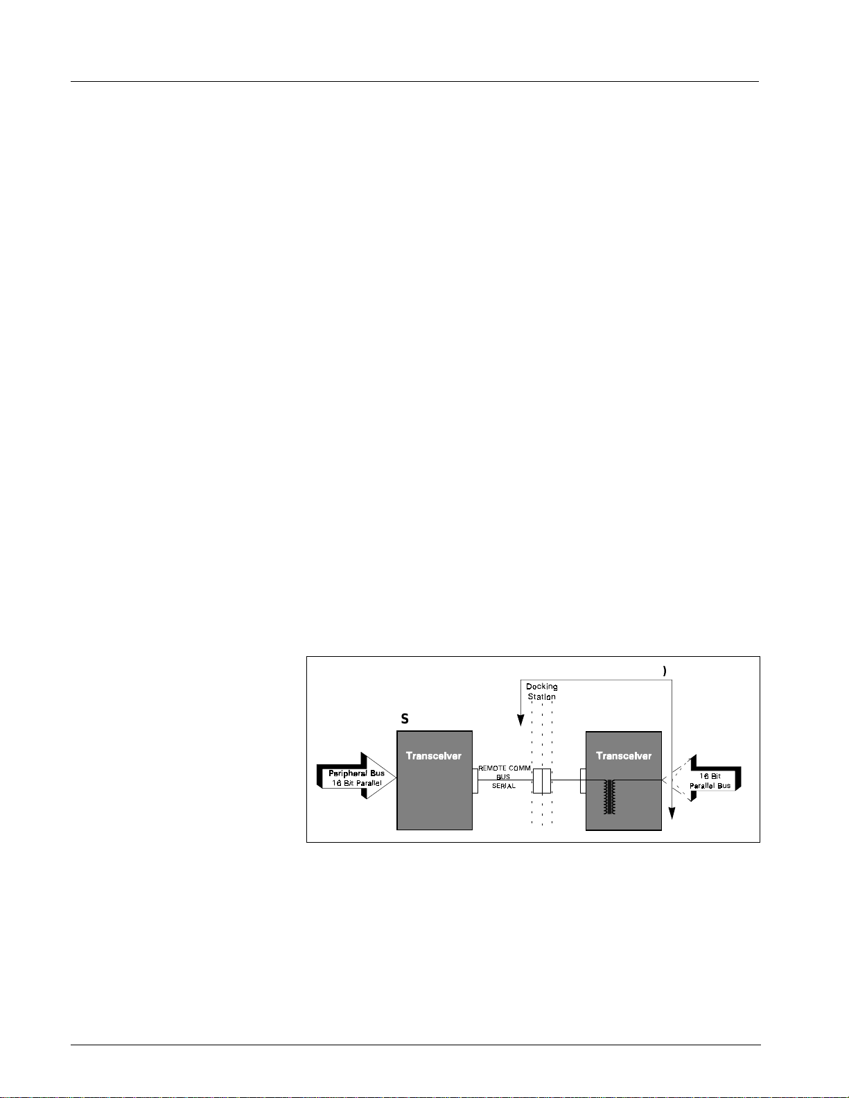
Service Manual SC 7000 and SC 9000XL Patient Monitors
8 Siemens Medical Systems, EM-PCS, Danvers ASK-T898-03-7600
NOT A CONTROLLE D DOCUMENT
7k9kXLTM.c2. CD_R OM .fm/0 4-99/ k aupp
1.1 Main Processo r Bus
The Main processor bus is a 32 bit data bus connecting the MPC860 to its
main bank of 16 meg DRAM memory. The Program for the monitor is stored
in 8 meg Flash memory and uploaded to DRAM during initialization. The
DRAM is optimized for multiple word transfers allowing efficient cache fills.
This bus has an optional daughter card connector allowing expansion of the
main memory space. The graphics controller is connected to this bus to
allow high bandwidth access to video memory. The bus has a max
bandwidth of 40 megbytes/sec.
This bus also has an I/O space implemented in an FPGA. These functions
include audio, chart recorder interface, keypad and rotary knob interface,
and EEPROM. The EEPROM con tains serial #’s, calib ration const ants and
configurations. The I/O space also includes the Bridge to the FRONT END
bus and a port to the REMOTE COMM bus. The Bridge to the FRONT END
bus is unidirectional. This means that the Main processor may read and
write to the FRONT END bus, but the Front end processor can not access
the MAIN bus.
1.2 Front End Bus
The Front End bus is a 32 bit data bus connecting the second MPC860 to
its main bank of 4 meg DRAM memory. The program for this processor is
downloaded from the main processor during initialization. The DRAM is
optimized for multiple word transfers allowing efficient cache fills. Both
processors contain 512K of battery-backed SRAM for trend and other
patient data storage. Data is exchanged through the common memory.
This bus has multiple bus masters that include the following:
• Front End 860
• Main 860
• DSP DMA
• POD Comm DMA (a POD is a configured front end)
• DRAM Refresh
Figure 2-2 REMOTE COMM Bus
1.3 REMOTE COMM Bus
The R EMOTE COMM b us ( Figure 2-2) is a bus extender used to extend the
main bus to a second chassis. The parallel address bus and data bus are
serialized using high speed FDDI transceivers, allowing virtual parallel
access to a remote parallel bus. The parallel bus is located in the CPS
communication power supply module or in the Iinfinity Docking Station
(IDS). This bus interfaces to a network controller and other local serial
buses including MIB, lGraphics, Gas Monitoring, and other peripherals. The
host is stalled until completion of all read operations, but is released after a
write is latched to be serialized.
CPS
IDS (= Dk. Sta. + XCVR
SC 9000X
L
SC 7000/
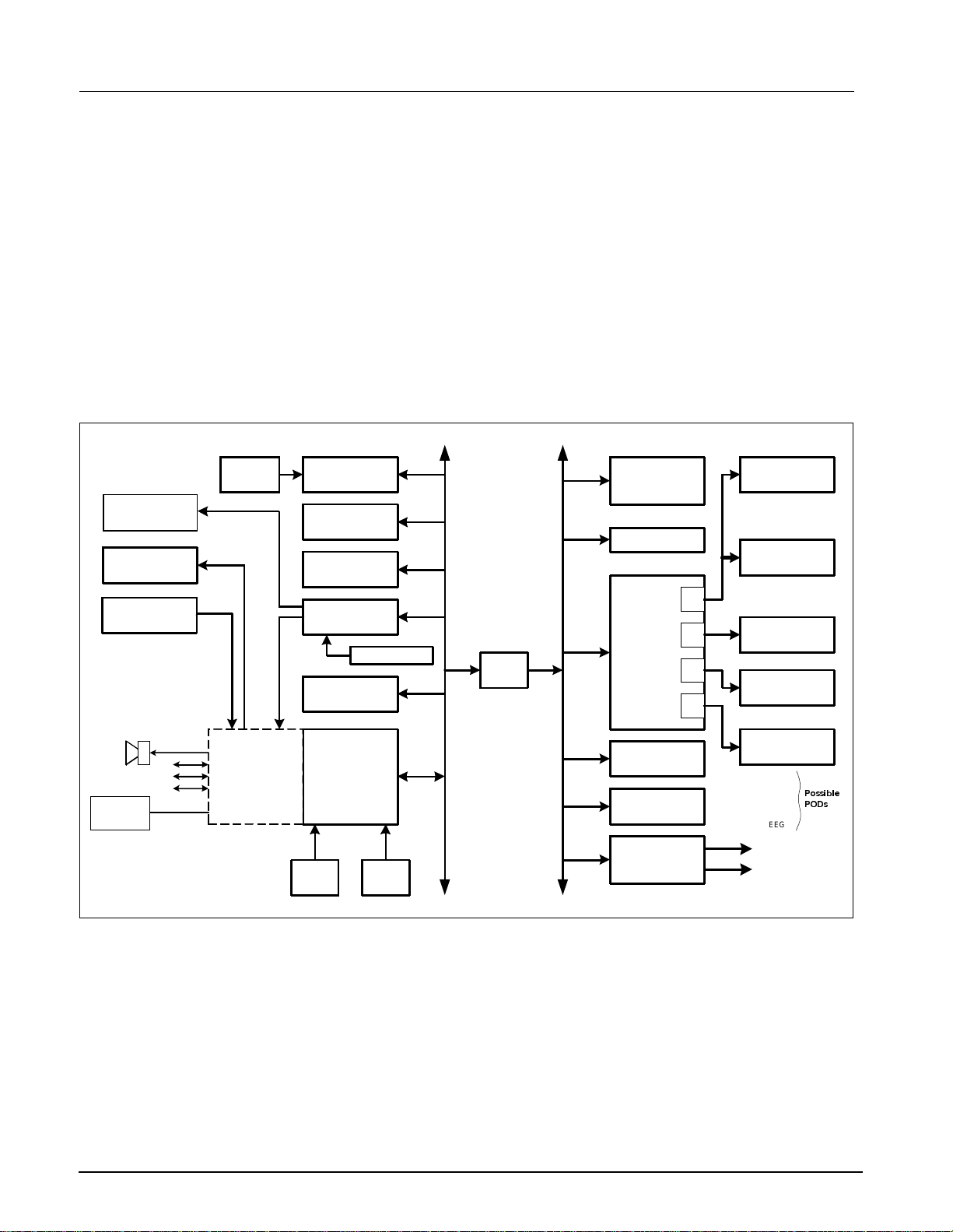
SC 7000 and SC 9000XL Patient Monitors Service Manual
ASK-T898-03-7600 Siemens Medical Systems, EM-PCS Danvers 9
7k9kXLTM.c2.CD_ROM.fm/04-99/kaupp
NOT A CONTROLLE D DOCUMENT
1.4 Error Handling
The hardware provides several cir cuits for error detection, error recovery,
and safety. The main proce ssor bus, f ront end pr ocessor bus, and REMOTE
COMM bus both have timeouts implemented w ith the arb iter to pre vent a lock
up of the sy st em . T he RE M O T E C OMM bus al so contain s a C RC for serial
transmis sion to and from t he CPS or IDS. I f a b ad CRC is detected an
interrupt is sent to the mai n 860. The main 860 and the Front End 860 are
both protec ted with watchdog t imers. I f a timer expi res, the system i nitiate s a
reset and restarts the monitor.
The power supply is also monitored with a piezo alarm that sounds during
power up (for test) and power down. This is to alert the user that the monitor
has turned off. The piezo alarm does not sound during a "Pick and Go"
since the monitor switched to battery operation without interruption. The
piezo is also sounded continuously if the monitor does not reset properly
after a watchdog timer has expired and the computer has halted.
Figure 2-3 SC 7000 / SC 9000XL Block Diagram
2Main Unit
Both monitors are designed to be lightweight and portable. The division of
the REMOTE COMM bus and internal buses are a direct mapping of what
is needed during transport and what can be left in the patient’s room. The
REMOTE COMM bus is connected and disconnected via a docking station
which has a locating feature for the monitor as well as a locking latch. The
main unit has been designed as a single board computer. In addition to the
main board there is a front bezel board to interface to a flat panel display,
and a connector board used as a cable harness in the rear chassis. The
main processor board contains three sections (see Figure 2-3): processor,
power conversion, and front end. Each section is shielded from the others.
Memory
Card
Internal
Battery
I/O Interfaces
Remote Comm
RAM Memory
VGA Graphics
Flash Memory
RAM Memory
860
Main Processor
LCD Display
Front Panel
Controls
External
Battery
Front Panel
Audio
Uart & Comm
Alarm Out
Keypad
RT Clock
Recorder
Chart
Recorder
860
Front End
Processor
Pod 2
Pod 1
etCO2 Cartridge
HemoMed Pod
MultiMed Pod
I/O Interface
NBP
2181 DSP
POD
Com
RAM Memory
Bridge
Analog Out
QRS Sync
ECG/Resp
Temp
SpO
2
HEMO2
HEMO4
12 Lead
tcpO
2
A
B
C
D
Press
C.O.
CRT
3RVVLEOH
32'V
EEG

Service Manual SC 7000 and SC 9000XL Patient Monitors
10 Siemens Medical Systems, EM-PCS, Danvers ASK-T898-03-7600
NOT A CONTROLLE D DOCUMENT
7k9kXLTM.c2. CD_R OM .fm/0 4-99/ k aupp
Processor Section The processor section co nt ai ns all compute r f unctions of t he m onitor. It
contains t wo M P C 860 processors, a VGA graph ics controll er, and a 2181
DSP. All of t hese devices co mmunicate using one large FPGA (field
programmable gate array) that is downloaded at init ial ization. The F P GA
contains all custom circuitry used in t he computer, including the processor
bridge, remote comm transmitter, pod com DMA, DSP interface, NBP
interfac e, and I/O interface s for both processors. Configur at i on of the FP GA
may be updat ed with the Software throu gh t he m em ory card adapter.
Power Conversion Section The power conversion section operates on a DC input from +11 to +15
volts. It switches between the external supply, the external battery and the
internal battery for the proper power source, and generates all necessary
dc voltages for the unit. It charges and maintains the internal and external
battery. This section also contains the patient isolation for the two internal
front ends as well as two general pod comm ports. It also has the power
control for the NBP pneumatics.
Front End Section The front en d cont ain s Multi Med and HemoM ed circ uit ry. T he M utiM ed fro nt
end provid es the following parameters ; 6-lead ECG, Respi ration, Puls e
Oximetry , and Temp erature . The NBP pressur e transd ucer is al so con tained
in this front end. The fr ont end is based on a si ngle 16 bit over sampling
converte r. Oversampling allows for a reduction i n anti-aliasing anal og
circuit ry while maintaini ng superior noise r ej ec tion. The HemoMed front end
provides four invasi ve pressures and Thermal Dilution Cardiac Output.
2.1 Front Bezel Board
The front bezel board is an interface board used to adapt a particular LCD
panel to the processor board. It also interfaces the front bezel rotary knob
and keypad to the processor. The front bezel board contains the backlight
invertor with a PWM input to allow for LCD brightness control in order to
save power.
2.2 Cooling System
The cooling system for the main monitor is convection based and uses a
patented chimney approach. The chimney is comprised of a heatsink which
cools the electronics and a plate which cools the LCD backlight. The
chimney is in the middle of the monitor and therefore is vented on top and
bottom. These vents should remain unobstructed for proper operation. The
chimney is waterproof and accidental liquid entering the chimney is safe.
CARE should be taken to operate the monitor below 45° C and store the
monitor below 60° C, since damage to the LCD can occur at 70° C. If the
internal temperature of the circuit board exceeds 80° C the monitor shuts
down to prevent damage to the electronics. The monitor does not restart
until the temperature is below the shut off value.
2.3 Real Time Clock
The Real Time Clo ck fu n ction is implemented with the EPSON- SEIKO
RTC4513 device, and is synchronized by the Central Station.
2.4 Non-volatile Memory
Battery Backup and
Power Reset
The shared RAM and real time clock are provided with a lithium battery
backup circuit to prevent corruption of this non-volatile memory during a
power loss condition (both primary and battery power are lost). Note that
the battery used for non-volatile memory backup should not be confused
with the internal and external batteries that are used to provide power to the
monitor base unit when primary power is lost. Non-volatile memory lithium
battery backup is controlled by a power supervisory device that provides a
power reset during a power loss condition.
Note: No provisions have been made to recharge this non-volatile
memory backup battery. Eventually (≈10 years), the battery must be
replaced.

SC 7000 and SC 9000XL Patient Monitors Service Manual
ASK-T898-03-7600 Siemens Medical Systems, EM-PCS Danvers 11
7k9kXLTM.c2.CD_ROM.fm/04-99/kaupp
NOT A CONTROLLE D DOCUMENT
2.5 MPC 860
Communication
Channels
MPC 860 has an embedded communicat ions proces sor capable of
executing several protocols such as UART or Ethernet. The 860
communications channels are used as follows:
Main Processor SCC1 Ethernet 10 Mbits/sec (future option)
SCC2 SC 9015 UART selectable baud
SCC3 MVP-1 UART selectable baud
SCC4 MVP-2 UART selectable baud
SMC1 main diag UART 19.2 Kbaud
SPI a/d (power monitor)
Front End Processor SCC3 serial pod data
SCC4 serial pod data
SMC1 front end diag UART
An additional UART implemented in the FPGA contains a large FIFO and
interfaces to the chart recorder.
2.6 Device CPS
A CPS (communication, power supply) has three boards -- power supply,
network board, and connector board, and allows for connection to an
INFINITY network as well as MIB and CAN. The FPGA and main program
memory are downloadable by the SC 7000 and SC 9000XL. The power
supply is a medical grade universal supply operating from 88 to 264 vac.
The Docking Station is a passive device that serves as a sturdy mount for
SC 7000 and SC 9000XL (as well as SC 9000 and SC 6000 series patient
monitors), in support of the P
ICK
-
AND
-G
O
concept, and provides pass-
through signals between the monitor and the CPS.
2.7 Infinity Docking
Station
The Infinity Docking Station base unit (IDS) with its separate power supply,
replaces the CPS and Docking Station combination in an I
NFINITY
N
ETWORK
. As a docking station, it serves as a secure mount for the patient
monitors, as above, and also provides the network and peripheral device
connectivity of a Basic CPS. When equipped with a MIB 1-2 Option, it
provides the functionality of a Device CPS and Breakout Box.
2.8 etCO
2
cartridge
The etCO
2
cartridge is a hardware component attached to the back of the
SC7000 or SC 9000XL. The cartridge is a self contained computer capable
of mainstream and side stream measurements.
2.9 External Battery
The external battery is a low cost lead acid battery and may be charged in
either the monitor or with an external charger. The external battery may be
hot-swapped to extend battery life during transport.
2.10Interfaces
2.10.1 Local Fixed Keys Interface There are twelve fixed function keys on the monitor base unit, and a fixed
key dedicated as a power on/off switch. The power on/off switch is unique
in that it is not directly available via a status read command. The on/off
switch is input to the power supply subsystem interface, where the switch
state is detected and processed. Detection of a power off condition causes
an interrupt to the host processor.
2.10.2 Local Rotary Knob Interface The rotary knob is a 16 detent rotary knob. Each detent position indicates
a "click" clockwise or counter-clockwise. The change in detent position is
detected via a 2 bit quadrature code that changes value every time the
rotary knob is moved into a detent position. Also included in the rotary knob
is a push button switch that is operated by a press/release action. This
switch is used to select menu items on the screen.

Service Manual SC 7000 and SC 9000XL Patient Monitors
12 Siemens Medical Systems, EM-PCS, Danvers ASK-T898-03-7600
NOT A CONTROLLE D DOCUMENT
7k9kXLTM.c2. CD_R OM .fm/0 4-99/ k aupp
2.10.3 SC 9015 Interface The SC 9015 Interface is implemented in the main processor
communication channels. SCC2 has been dedicated as the channel
between the remote monitor and the base unit, and provides a full duplex
transmit/receive channel from/to the remote monitor. This interface enables
the fixed keys and rotary knob on the remote display to control the main
unit, in parallel with controls on the main unit.
2.10.4 Fast Analog Output The ANALOG OUT interface consists of two identical channels. Each
ANALOG OUT channel provides a 12 bit D/A function. The design uses a
dual DAC to produce the D/A conversion. The sampled analog data is then
passed through a 2 pole low pass filter. The analog output has a maximum
delay of 20ms, and can be used for a defibrillator or balloon pump.
Separate Pacer Spike generation circuits for analog outputs 1 and 2 are
provided.
2.10.5 HiFi Audible Alarm Interface The Audible alarm interface consists of an FM synthesis and Audio DAC
chip set. There is also power amplifier drive circuitry for the two speaker
interfaces: the internal speaker located in the base unit and the speaker
located in the remote CRT. Circuitry has been included to provide a
mechanism for automatically generating an error tone when a watchdog
failure occurs via the piezo alarm (see Section 6.1.8)).
The chip is loaded with tone frequency, pitch, harmonics, and volume
information by the host processor, which controls the duration of the tone.
The audio DAC converts the received sampled tone data and produces a
sampled analog representation of the tone data.
The local speaker interface (also designated as main speaker interface) is
designed for an 8 ohm speaker load. This local speaker interface produces
1 watt of power into an 8 ohm load, and has thermal shutdown capability.
The remote speaker interface is designed to produce a 1Vrms maximum
signal into a 1 kohm load, and provides an ac coupled output.
2.10.6 LED/Status Interface Fi ve LEDs provide information in the present SC 7000 and SC 9000XL
configurations. Two are dedicated to the front end processor, to the DSP,
and two to the main processor.
2.10.7 QRS Sync Out Interface A QRS sync output is provided. The QRS SYNC OUTPUT is an open
collector type output driver that is pulled up to +12 volts (active HIGH). The
output is initialized to Gnd on reset or power on.
This QRS signal is available via an external connector mounted on the main
PC board. High level = +6V min (10KΩ load), +12.6V (no load); Low level
(no QRS) = 1V @ 5ma.
2.10.8 Local Alarm Out Interface A Local Alarm output is provided. This Local Alarm Output is an open
collector type output driver that is pulled up to +12 volts. The output is
initialized to ground (0 volts) on reset or power on (active HIGH).
Loopback status is available via a status read command.
The Local Alarm Out signal is available via an external connector mounted
on the main PC board.
2.10.9 Remote Alarm Out Interface
for Nurse Call
The Remote Alarm Output Interface is located in the CPS/IDS subsystem.
This output is an open collector output with a +12V pullup resistor, fed from
the monitor. The Remote Alarm Output is silenced when a monitor is
undocked.
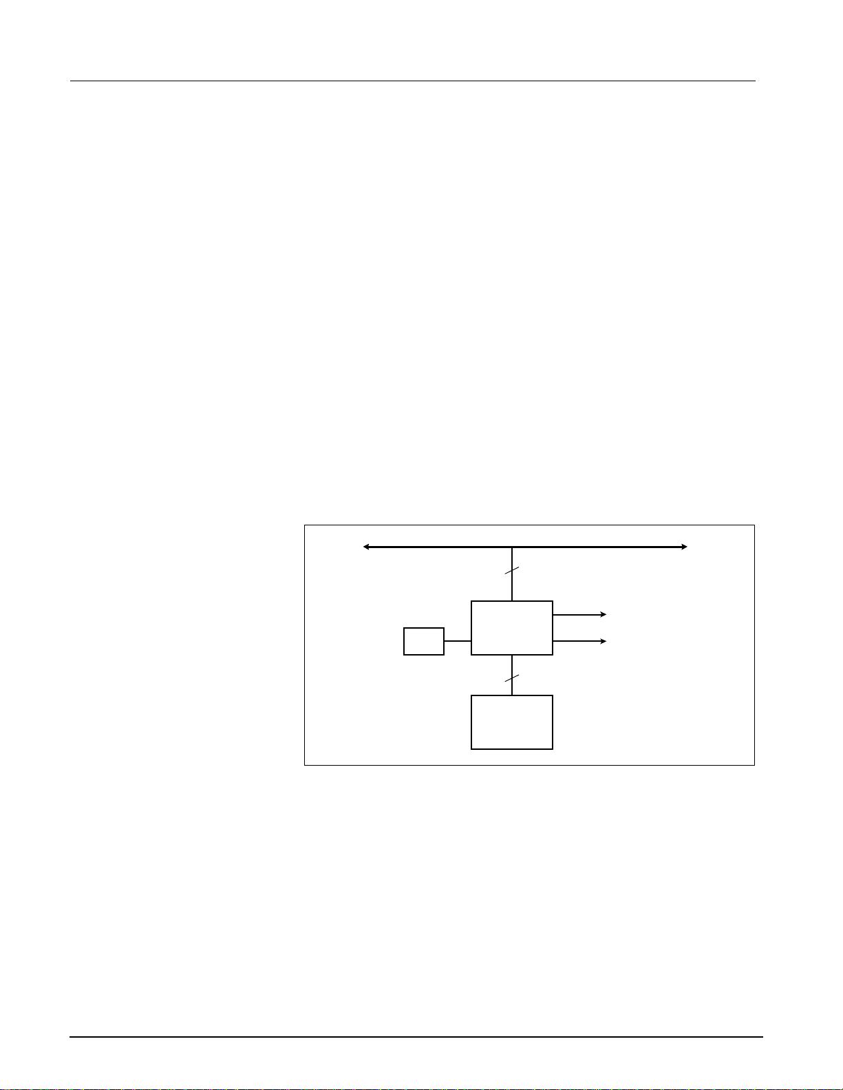
SC 7000 and SC 9000XL Patient Monitors Service Manual
ASK-T898-03-7600 Siemens Medical Systems, EM-PCS Danvers 13
7k9kXLTM.c2.CD_ROM.fm/04-99/kaupp
NOT A CONTROLLE D DOCUMENT
2.11Recorder Interface
The Recorder interface has been designed to connect to an external
recorder via the base unit docking station connector. The recorder interface
provides all of the necessary control, data and power supply signals
required to drive an external recorder. The interface consists of current
limited DC power and a UART with handshake signals. The UART is
implemented in the main processor FPGA to allow for an extended FIFO.
2.12Backlig ht Cont rol
SC 7000 and SC 9000XL displays require a fluorescent backlight for visibility.
The backli ght in vertor is located o n the fr ont beze l board . Intens ity of th e lig ht
is control led by a variable power ac i nverter and i s bas ed on ambient l ight
detection as well a s operator se l ection. A 10 KH z 6 bi t PWM is implemented
in the main processor FPGA, and a filter on the front bezel b oard converts
this digital signal to an analog volt age to control t he backlight i ntensity.
2.13Serial EEPROMS
Four serial EEPROM devices, which contain the Monitor serial number,
Ethernet address, NBP pneumatic characterization and calibration
constants, and monitor setups, are located on the connector I/O board and
are part of the rear housing. If the main processor board is replaced the
monitor will keep its set ups from the se serial EE PR OM s.
Two EEPROMs can be written only at the factory, and contain the Monitor
serial number and Ethernet ID address. The other devices are writable by
the main processor and are changed during service menu setups. These
devices are used for the monitor as well as network setups, device
compatibility, and software feature locks.
Figure 2-4 Graphics Subsystem
3Graphics Subsystem
3.1 Overview
The Graphics Subsystem is based on a commercial VGA controller (see
Figure 2-4), and drives both a CRT and LCD display from a local memory
used to refresh the screen. It uses a special video crystal which enables it
to synchronize to most video standards. The graphics chip is capable of
running resolutions such as 800 x 600, when these displays are added to
the monitor. The standard resolution is set to 640 X 480.
3.2 Functional Description
The VGA subsystem is designed to optimize the Bitblit operation, which
allows for quick updates of the screen. This is accomplished by writing
images to non-viewable areas of video memory before they are needed and
copying them to the screen on demand. The copy function is performed by
the VGA controller.
VGA Controller
CRT Interface
LCD Interface
MAIN BUS
DRAM Video
Buffer
Video
Crystal
32
32
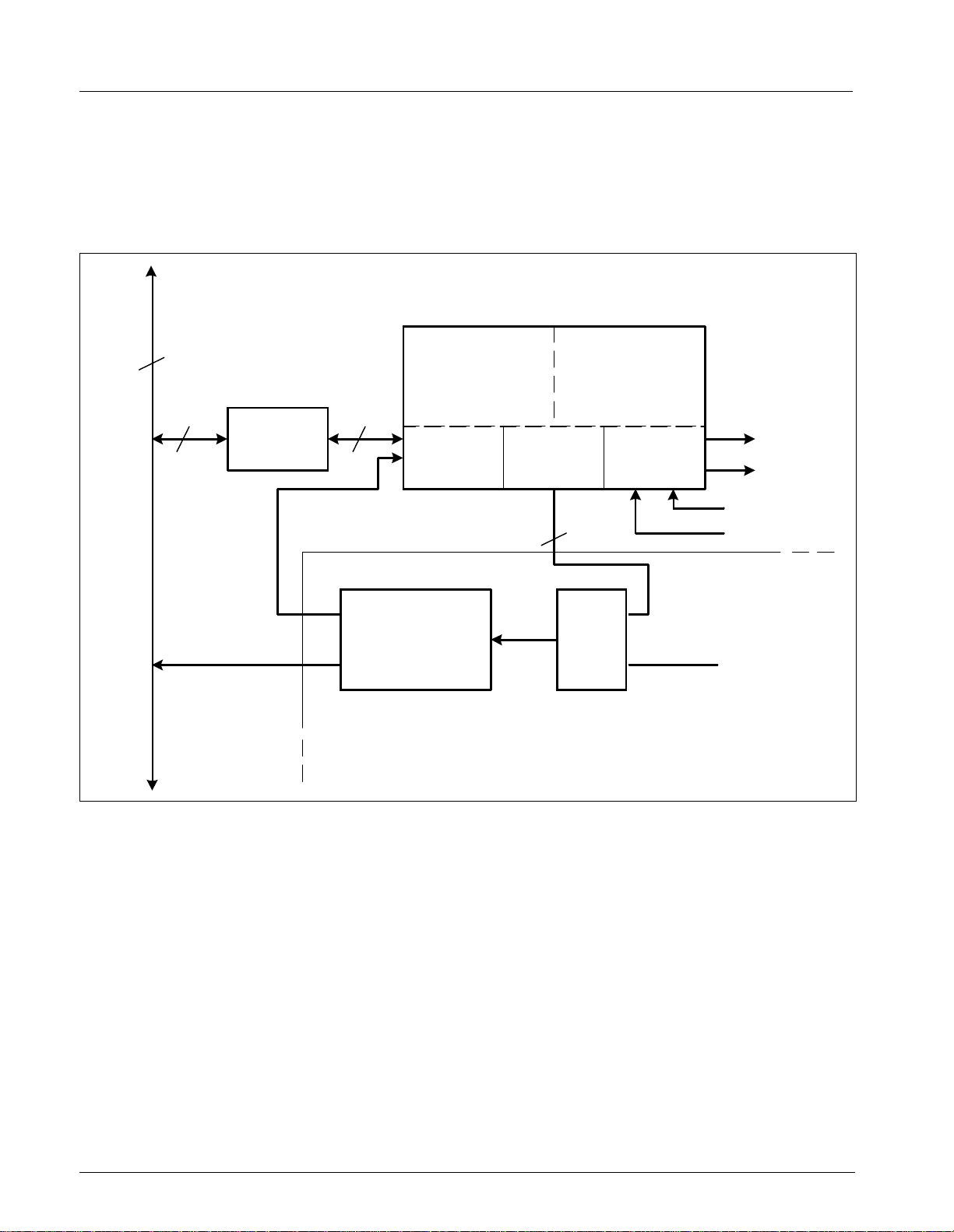
Service Manual SC 7000 and SC 9000XL Patient Monitors
14 Siemens Medical Systems, EM-PCS, Danvers ASK-T898-03-7600
NOT A CONTROLLE D DOCUMENT
7k9kXLTM.c2. CD_R OM .fm/0 4-99/ k aupp
3.3 Video Output
The Graphics Subsystem provides output to an internal flat panel display,
while simultaneously providing the same output for a remote analog
display. The remote display signals are available on the docking station
connector and can drive a standard VGA monitor. The CRT interface uses
three 8 bit DACs for its three color outputs. The front bezel interface is
digital and contains 6 bits for each color.
Figure 2-5 DSP Subsystem
4 DSP Subsystem
The monitor uses a DSP for preprocessing of oversampled data (see
Figure 2-5). The DSP is a specialized microprocessor that executes high
speed repetitive functions such as digital filters. The DSP acquires data
from the incoming serial pod comm data streams. The data sent to the DSP
is selected by the control words in the pod com memory buffer. Typically
only high acquisition rate data is sent to the DSP.
The DSP has two other communication ports both of which can access the
internal 32Kword memory. The IDMA port is used to DMA data to and from
the common memory. Bus sizing logic converts the DSP 16 bit port to the
32 bit FRONT END bus. During initialization this path is used to download
code to the DSP. The main processor takes control of the DMA port during
this time. Once the system is operational the DSP takes control of the DMA
controller by using its I/O port. The I/O port is a dedicated 8 bit path into the
main FPGA, which allows the DSP access to the DSP DMA controller as
well as other internal FPGA registers, including analog out and QRS sync.
Bus
Sizing
DSP
Engine
32 Kwords
SRAM
IDMA
Port
I/O
Port
Serial
Ports
2181 DSP
DSP DMA
Controller
MUX
Main Processor
(Download)
Front End
Processor
8
32 16
Main FPGA
Memory
Address
Control
32
Front
End
Bus
Pod Com C & D
Pod Com A & B
Loading...