


 Loading...
s
SC 7000 and SC 9000XL Patient Monitors SC 9000XL Monitor 12in (30.5cm) Display
Service Manual Supplement Two
EM Guidelines, 1997-04-02
E331.E539U.640.10.03.02 ASK-A898-03-7600
Page 1 of 16
Service Manual Supplement Two - 12in (30.5cm) Display |
SC 9000XL Patient Monitors |
|
|
Table of Contents
1 Introduction . . . . . . . . . . . . . . . . . . . . . . . . . . . . . . . . . . . . . . . . . . . . . . . . . . . . . . . . . . . . . . . . . . . . 3
Chapter 3 . |
. . . . . . . . . . . . . . . . . . . . . . . . . . . . . . . . . . . . . . . . . . . . |
. . . . . . . . 3 |
||
2 Opening Monitor . . . . . . . . . . . . . . . . . . . . . . . . . . . . . . . . . . . . . . . . . . . . . . . . . . . . . . . . . |
. . . . . . . 3 |
|||
|
2.1 |
Removing/Installing Side-Panels . . . . . . . . . . . . . . . . . . . . . . . . . . . . . . . . . . . . . . . . . . . |
. . . . . . 3 |
|
|
2.2 |
Separating Front Bezel Subassembly and Rear Housing Subassembly . . . . . . . . . . . . . |
. . . . . . 3 |
|
|
Figure 3-1 Locking Plates for Front Bezel Subassembly . . . . . . . . . . . . . . . . . . . . . . . . . . |
. . . . . . 3 |
||
|
Figure 3-2 Latch Locking Clips on Bottom of Monitor (only one shown) . . . . . . . . . . . . . . |
. . . . . . 4 |
||
|
Figure 3-3 Bottom Release Tabs for Front Bezel Subassembly . . . . . . . . . . . . . . . . . . . . . |
. . . . . . 4 |
||
|
Figure 3-4 SC 9000XL w/ 12in (30.5cm) Display . . . . . . . . . . . . . . . . . . . . . . . . . . . . . . . . |
. . . . . . 5 |
||
3 |
Replacing Subassemblies in Rear Housing . . . . . . . . . . . . . . . . . . . . . . . . . . . . . . . . . . . . . . |
. . . . . . 5 |
||
|
3.1 |
Removing/Installing Funnel . . . . . . . . . . . . . . . . . . . . . . . . . . . . . . . . . . . . . . . . . . . . . . . |
. . . . . . 5 |
|
|
Figure 3-5 |
Front Bezel Subassembly Components. . . . . . . . . . . . . . . . . . . . . . . . . . . . . . . . . . . . . 6 |
||
4 |
Accessing Replaceable Subassemblies in Front Bezel Subassembly . . . . . . . . . . . . . . . . . . |
. . . . . . 6 |
||
|
Figure 3-6 Front Bezel Subassembly - Interior View, Plastic Frame Removed . . . . . . . . . . |
. . . . . . 7 |
||
|
Figure 3-7 Front Bezel Subassembly - Interior View, Retainer Plate Removed . . . . . . . . . |
. . . . . . 7 |
||
|
4.1 |
Removing Plastic Frame and Metal Retainer Plate . . . . . . . . . . . . . . . . . . . . . . . . . . . . . |
. . . . . . 8 |
|
|
|
4.1.1 Removing Plastic Frame and Metal Retainer Plate . . . . . . . . . . . . . . . . . . . . . . . . |
. . . . . . 8 |
|
|
|
4.1.2 Reinstalling Plastic Frame and Metal Retainer Plate . . . . . . . . . . . . . . . . . . . . . . . |
. . . . . . 8 |
|
|
4.2 |
Optical Encoder Subassembly . . . . . . . . . . . . . . . . . . . . . . . . . . . . . . . . . . . . . . . . . . . . . |
. . . . . . 8 |
|
|
Figure 3-8 |
Optical Encoder Subassembly. . . . . . . . . . . . . . . . . . . . . . . . . . . . . . . . . . . . . . . . . . . . 8 |
||
|
|
4.2.1 Removing Optical Encoder Subassembly . . . . . . . . . . . . . . . . . . . . . . . . . . . . . . . |
. . . . . . 8 |
|
|
|
4.2.2 Installing Optical Encoder Subassembly . . . . . . . . . . . . . . . . . . . . . . . . . . . . . . . . |
. . . . . . 9 |
|
|
4.3 |
Front Bezel PC Board . . . . . . . . . . . . . . . . . . . . . . . . . . . . . . . . . . . . . . . . . . . . . . . . . . . . |
. . . . . . 9 |
|
|
|
4.3.1 Removing Front Bezel PCB . . . . . . . . . . . . . . . . . . . . . . . . . . . . . . . . . . . . . . . . . . |
. . . . . . 9 |
|
|
|
4.3.2 Installing Front Bezel PC Board . . . . . . . . . . . . . . . . . . . . . . . . . . . . . . . . . . . . . . . |
. . . . . 10 |
|
|
Figure 3-9 |
Display Subassembly . . . . . . . . . . . . . . . . . . . . . . . . . . . . . . . . . . . . . . . . . . . . . |
. . . . . 10 |
|
|
4.4 |
Replacing Backlights . . . . . . . . . . . . . . . . . . . . . . . . . . . . . . . . . . . . . . . . . . . . . . . . . . . . |
. . . . . 11 |
|
|
4.5 |
Front Bezel/Lens Subassembly . . . . . . . . . . . . . . . . . . . . . . . . . . . . . . . . . . . . . . . . . . . . |
. . . . . 11 |
|
|
4.6 |
Front Bezel Subassembly . . . . . . . . . . . . . . . . . . . . . . . . . . . . . . . . . . . . . . . . . . . . . . . . |
. . . . . 11 |
|
5 |
Closing Monitor . . . . . . . . . . . . . . . . . . . . . . . . . . . . . . . . . . . . . . . . . . . . . . . . . . . . . . . . . . . |
. . . . . 11 |
||
Appendix A |
. . . . . . . . . . . . . . . . . . . . . . . . . . . . . . . . . . . . . . . . . . . . |
. . . . . . 13 |
||
|
Figure A-5 Front Bezel Subassembly Components . . . . . . . . . . . . . . . . . . . . . . . . . . . . |
. . . . . 13 |
||
|
|
Table A-5 Front Bezel Subassembly - Replaceable Parts/Subassemblies . . . . . . . . . . . |
. . . . . 13 |
|
|
Figure A-6 Rear Housing and Funnel (Exploded View)l . . . . . . . . . . . . . . . . . . . . . . . . . . |
. . . . . 14 |
||
|
|
Table A-6 Rear Housing and Funnel . . . . . . . . . . . . . . . . . . . . . . . . . . . . . . . . . . . . . . . |
. . . . . 14 |
|
|
|
|
||
Page 2 of 16 |
Siemens Medical Systems, EM-PCS, Danvers |
ASK-A898-03-7600 |
||
9kXL_12inDspl.sm_sup.fm/06-99/kaupp
SC 9000XL Patient Monitors |
Service Manual Supplement Two - 12in (30.5cm) Display |
|
|
1 Introduction
Information in this supplement is applicable to only SC 9000XL monitors factory equipped with a 12” (30.5cm) Display. It replaces information in the SC 7000 and SC 9000XL Patient Monitors Service Manuals as indicated below.Refer to either the printed version of the Service Manual (Art. No. 5949016E539U) and Supplement (Art. No. 5952416E539U) or to the CD-ROM version (Art. No. 5944090E539U) for all other service information.
N.B: The 12” (30.5cm) Display Front Bezel Subassembly is not compatible with and cannot be installed on SC 7000 Monitors nor on SC 9000XL Monitors factory equipped with 10.4” Displays.
Section references used in this supplement refer to the section numbers in the printed Service Manual or CD-ROM. Changes impact primarily Chapter 3, Repair, and Appendix A, Replacement Parts.
Chapter 3
5 Opening Monitor
The impacted sections of Chapter 3 in the Service Manual are reproduced below with appropriate changes. Some text and graphics that remain unchanged from the material in the Service Manual, are included below as a convenience. Sections NOT rewritten below, remain unchanged.
Before attempting to open the monitor, always do the following:
•Remove all attached modules and unplug all cables from the monitor.
•Disconnect all external power sources, remove external battery (if installed), and remove back cover and unplug cable from main battery.
•Assure that both you and the work area are properly protected against static-electricity discharge.
5.1Removing/Installing Refer to procedure in Service Manual.
Side-Panels
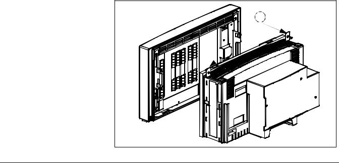
5.2Separating Front Bezel After left and right side panels have been removed, opening the monitor Subassembly and Rear consists of separating the front bezel and rear housing subassemblies. The Housing Subassembly subassemblies are secured to each other by two locking tabs on the rear
housing at the bottom of the front bezel and two locking plates that secure the top of the bezel to the rear housing (see Figure 3-7).
1 |
Figure 3-7 Locking Plates for Front Bezel Subassembly |
ASK-A898-03-7600 |
Siemens Medical Systems, EM-PCS Danvers |
Page 3 of 16 |
9kXL_12inDspl.sm_sup.fm/06-99/kaupp
Service Manual Supplement Two - 12in (30.5cm) Display |
SC 9000XL Patient Monitors |
|
|
1Place monitor in its upright position, with back of monitor facing you.
2Remove and save two screws and locking plates (see a in Figure 3-7) that secure top of Front Bezel Subassembly to rear housing.
1  2
2 
~
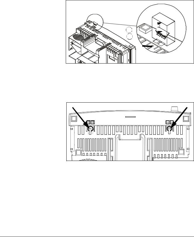
Figure 3-6a Latch Locking Clips on Bottom of Monitor (only one shown)
3Turn monitor topside down, as shown in Figure 3-6a if locking clips are installed. If locking clips are not installed, go to step 5.
4Peel off and save tape (a in Figure 3-6a) and remove and save locking clips (s in Figure 3-6a) from the two latches on the bottom of the monitor.
Figure 3-6 |
Bottom Release Tabs for Front Bezel Subassembly |
5Place monitor backside down with bottom of monitor facing you as shown in Figure 3-6.
6Press in firmly on thumb depressions on bottom of monitor to release latches (see arrows in Figure 3-6), and pull up on bezel to slightly separate left side of Front Bezel Subassembly from Rear Housing Subassembly.
7Carefully pull right-hand side of Front Bezel Subassembly up from rear housing to unplug interfacing connector on back of front bezel PC board from corresponding connector on main processing board.
8Lift Front Bezel Subassembly off of rear housing to separate the two subassemblies.
9Store subassemblies in safe location as necessary.
Page 4 of 16 |
Siemens Medical Systems, EM-PCS, Danvers |
ASK-A898-03-7600 |
9kXL_12inDspl.sm_sup.fm/06-99/kaupp

SC 9000XL Patient Monitors |
Service Manual Supplement Two - 12in (30.5cm) Display |
|
|
2
6
7
2
4
5 |
5 |
|
|
Rear Housing Subassembly |
3 |
Main Processor PCB Subassembly |
1 |
Front Bezel Subassembly
Figure 3-8 (replacement) SC 9000XL w/ 12in (30.5cm) Display - Rear Housing Subasssembly, Main Processor PCB Subassembly, and Front Bezel Subassembly
6Replacing Subassemblies in Rear Housing
6.1Removing/Installing Funnel
Locking tabs in the rear housing have been removed (see hin Figure 3-8) to accommodate the 12in (30.5cm) Front Bezel Subassembly. With the exception of a slight change in the remove/install procedure for the funnel, however, all other procedures in this section of Chapter 3 in the Service Manuals remain unchanged.
Note: Items a, d, f, g and item g in Figure 3-8 correspond to text references in the SC7000 and SC9000XL Service Manuals. Items s, s and h are references for this supplement. Item j is a label that is removed for DirectNet operation of the Monitor.
The funnel has no locking tabs (s in Figure 3-8) but rather slides into channels designed to provide a snug fit in the top of the rear housing.
•To remove the funnel, grasp it firmly in the area of the former tab slots (s in Figure 3-8) and carefully work it out of the channels.
•To reinstall the funnel, slide it firmly into the guide channels, and seat it against the lip on the back of the main PC board heat sink.
ASK-A898-03-7600 |
Siemens Medical Systems, EM-PCS Danvers |
Page 5 of 16 |
9kXL_12inDspl.sm_sup.fm/06-99/kaupp
Loading...