


S5-135U-155U
Table of contents
 Loading...
Contents
SIMATIC
S5-135U/155U
System Manual
This manual has the
order number:
Notes on Using this Manual
and on the CE Symbol
Centralized and Distributed
Configuration of a Programmable Controller
Installation Guidelines
Central Controllers and
Expansion Units
Power Supply Units
CPUs, Memory Cards,
Memory Submodules,
Interface Submodules
Multiprocessor Operation/
Coordinators
Interface Modules
1
2
3
4
5
6
7
6ES5998-0SH21
12/98
C79000-G8576-C199
Release 06
Digital Input/Output Modules
Analog Input/Output Modules
Monitoring Module
Connector Assignments
Appendices
Appendix
Guidelines for Handling
Electrostatically-Sensitive
Devices (ESD)
Index
8
9
10
11
A
B

Safety Guidelines
!
#$.()0'*)/$).)*/$ .2#$#4*0.#*0'*. -1 /* ).0- 4*0-*2)+ -.*)'.! /4.2 ''./*
+-*/ //# +-*0/)*)) / ,0$+( )/# . )*/$ .- #$"#'$"#/ $)/# ()0'42-)$)"
/-$)"' )- (-& .!*''*2.*-$)"/*/# ' 1 '*!)" -
Warning
$)$/ ./#/ /#. 1 - + -.*)'$)%0-4*-.0./)/$'+-*+ -/4(" )- .0'/$!+-*+ -+- 0/$*).)*//& )
Note
-2.4*0-// )/$*)/*+-/$0'-'4$(+*-/)/$)!*-(/$*)*)/# +-*0/#)'$)"/# +-*0/*-/*+-/$0'+-/*!/# *0( )//$*)
Qualified Personnel
Correct Usage
!
!
!
# 1$ .4./ ((4*)'4 . /0+)*+ -/ $)*)%0)/$*)2$/#/#$.()0'
)'4 .#*0' ''*2 /*$)./'')2*-&*)/#$. ,0$+( )/0'$!$ + -.*). !$) .+ -.*).2#*- 0/#*-$5 /**(($..$*)/*"-*0))/*/"$-0$/. ,0$+( )/).4.6
/ (.$)*-) 2$/# ./'$.# .! /4+-/$ .)./)-.
*/ /# !*''*2$)"
Warning
#$. 1$ )$/.*(+*) )/.(4*)'4 0. !*-/# ++'$/$*). .-$ $)/# /'*"*-/# / #)$'
.-$+/$*))*)'4$)*)) /$*)2$/# 1$ .*-*(+*) )/.!-*(*/# -()0!/0- -.2#$##1 )
++-*1 *-- *(( ) 4$ ( ).
#$.+-*0/)*)'4!0)/$*)*-- /'4).! '4$!$/$./-).+*-/ ./*- . /0+)$)./'' *-- /'4)
*+ -/ )($)/$) .- *(( )
Caution
!
)" -*! 3+'*.$*)$!// -4$.$)*-- /'4- +' +' *)'42$/#.( *- ,0$1' )//4+
- *(( ) 4/# ()0!/0- -$.+*. *!0. // -$ .*-$)"/*/# ()0!/0- -.$)./-0/$*).
Warning
6
Trademarks
The reproduction, transmission or use of this document or its
contents is not permitted without express written authority.
Offenders will be liable for damages. All rights, including rights
created by patent grant or registration of a utility model or design, are
reserved.
$ ( ).
Bereich Automatisierungs- und Antriebstechnik
Geaschaeftsgebiet Industrie Automatisierungssysteme
Postfach 4848,D-90327 Nuernberg
R)R)R - - "$./ - /- (-&.*!
#$-+-/$ .0.$)"!*-/# $-*2)+0-+*. .)4*/# -)( .$)/#$.*0( )/2#$#- ! -/*/- (-&.($"#/
$)!-$)" 0+*)/# -$"#/.*!/# /- (-&*2) -.
Siemens Aktiengesellschaft
C7-633, C7-634 Control Systems
Disclaimer of LiabilityCopyright E Siemens AG 1993 All rights reserved
We have checked the contents of this manual for agreement with the
hardware and software described. Since deviations cannot be
precluded entirely, we cannot guarantee full agreement. However,
the data in this manual are reviewed regularly and any necessary
corrections included in subsequent editions. Suggestions for
improvement are welcomed.
E Siemens AG 1993
0% //*#)" 2$/#*0/+-$*-)*/$
6ES5998-0SH21

Contents
1 Notes on Using this Manual and on the CE Symbol 1-1. . . . . . . . . . . . . . . . . . . . . . .
Notes on Using this Manual 1-1. . . . . . . . . . . . . . . . . . . . . . . . . . . . . . . . . . . . . . .
Notes on the CE Symbol 1-4. . . . . . . . . . . . . . . . . . . . . . . . . . . . . . . . . . . . . . . . .
Notes for Machine Manufacturers 1-6. . . . . . . . . . . . . . . . . . . . . . . . . . . . . . . . . .
Safety Notes 1-7. . . . . . . . . . . . . . . . . . . . . . . . . . . . . . . . . . . . . . . . . . . . . . . . . . . .
2 Centralized and Distributed Configuration of a Programmable Controller 2-1. . .
2.1 Application 2-2. . . . . . . . . . . . . . . . . . . . . . . . . . . . . . . . . . . . . . . . . . . . . . . . . . . . .
2.2 Centralized and Distributed Configuration 2-3. . . . . . . . . . . . . . . . . . . . . . . . . . .
2.2.1 Installing a PLC with Centralized Configuration 2-4. . . . . . . . . . . . . . . . . . . . . .
2.2.2 Installing a PLC with Distributed Configuration 2-5. . . . . . . . . . . . . . . . . . . . . . .
2.3 Examples 2-6. . . . . . . . . . . . . . . . . . . . . . . . . . . . . . . . . . . . . . . . . . . . . . . . . . . . . .
3 Installation Guidelines 3-1. . . . . . . . . . . . . . . . . . . . . . . . . . . . . . . . . . . . . . . . . . . . . . . . . .
3.1 Principles of Installation of Systems for EMC 3-2. . . . . . . . . . . . . . . . . . . . . . . .
3.1.1 Overview of Possible Types of Interference 3-2. . . . . . . . . . . . . . . . . . . . . . . . .
3.1.2 The Most Important Basic Rules for Ensuring EMC 3-6. . . . . . . . . . . . . . . . . .
3.2 Installation of Programmable Controllers for EMC 3-8. . . . . . . . . . . . . . . . . . . .
3.2.1 Basic Rules for Assembling and Grounding the Inactive Metal
Parts 3-8. . . . . . . . . . . . . . . . . . . . . . . . . . . . . . . . . . . . . . . . . . . . . . . . . . . . . . . . . .
3.2.2 Example of Cabinet Assembly for EMC 3-9. . . . . . . . . . . . . . . . . . . . . . . . . . . . .
3.2.3 Example of Rack and Wall Mounting for EMC 3-11. . . . . . . . . . . . . . . . . . . . . . .
3.3 Wiring of Programmable Controllers for EMC 3-12. . . . . . . . . . . . . . . . . . . . . . .
3.3.1 Routing of Cables 3-12. . . . . . . . . . . . . . . . . . . . . . . . . . . . . . . . . . . . . . . . . . . . . . .
3.3.2 Equipotential Bonding 3-14. . . . . . . . . . . . . . . . . . . . . . . . . . . . . . . . . . . . . . . . . . . .
3.3.3 Shielding of Cables and Lines 3-15. . . . . . . . . . . . . . . . . . . . . . . . . . . . . . . . . . . . .
3.3.4 Special Measures for Interference-Free Operation 3-17. . . . . . . . . . . . . . . . . . .
3.3.5 Checklist for the Electromagnetically Compatible Installation
of Control Systems 3-19. . . . . . . . . . . . . . . . . . . . . . . . . . . . . . . . . . . . . . . . . . . . . .
3.4 Power Supplies for Programmable Controllers and I/Os 3-20. . . . . . . . . . . . . .
3.4.1 Power Supplies for Control Systems with SIMATIC S5 3-20. . . . . . . . . . . . . . .
3.4.2 Connecting the Programmable Controller and Load Power 3-21. . . . . . . . . . . .
3.4.3 Connecting Non-Floating or Floating Modules 3-26. . . . . . . . . . . . . . . . . . . . . . .
3.5 Interference-Free Installation of Centralized and Distributed
Interface Circuits 3-28. . . . . . . . . . . . . . . . . . . . . . . . . . . . . . . . . . . . . . . . . . . . . . . .
3.5.1 Interference-Free Installation of Centralized Interface Circuits 3-28. . . . . . . . .
3.5.2 Interference-Free Installation of Distributed Interface Circuits 3-28. . . . . . . . . .
3.6 Interference-Free Connection of Monitors 3-30. . . . . . . . . . . . . . . . . . . . . . . . . . .
System Manual
C79000-G8576-C199-06
iii

Contents
3.6.1 Interference-Free Connection of a Monitor to the CP of the S5
Controller 3-30. . . . . . . . . . . . . . . . . . . . . . . . . . . . . . . . . . . . . . . . . . . . . . . . . . . . . .
3.6.2 Shielding and Grounding 3-31. . . . . . . . . . . . . . . . . . . . . . . . . . . . . . . . . . . . . . . . .
3.7 Selection and Installation of Cabinets with SIMATIC S5 3-33. . . . . . . . . . . . . . .
3.7.1 Types of Cabinet 3-34. . . . . . . . . . . . . . . . . . . . . . . . . . . . . . . . . . . . . . . . . . . . . . . .
3.7.2 Clearances in Cabinets 3-34. . . . . . . . . . . . . . . . . . . . . . . . . . . . . . . . . . . . . . . . . .
3.7.3 Removal of Power Dissipation from Cabinets 3-37. . . . . . . . . . . . . . . . . . . . . . . .
3.7.4 Examples for Determining the Type of Cabinet 3-38. . . . . . . . . . . . . . . . . . . . . .
3.7.5 Determining the Power Dissipation of Modules 3-39. . . . . . . . . . . . . . . . . . . . . .
4 Central Controllers and Expansion Units Power Supply Units 4-1. . . . . . . . . . . . .
4.1 S5-135U/155U Central Controller 4-2. . . . . . . . . . . . . . . . . . . . . . . . . . . . . . . . . .
4.1.1 Technical Description 4-2. . . . . . . . . . . . . . . . . . . . . . . . . . . . . . . . . . . . . . . . . . . .
4.1.2 Installation 4-6. . . . . . . . . . . . . . . . . . . . . . . . . . . . . . . . . . . . . . . . . . . . . . . . . . . . .
4.1.3 Startup 4-10. . . . . . . . . . . . . . . . . . . . . . . . . . . . . . . . . . . . . . . . . . . . . . . . . . . . . . . . .
4.1.4 Repair Guidelines 4-12. . . . . . . . . . . . . . . . . . . . . . . . . . . . . . . . . . . . . . . . . . . . . . .
4.1.5 Technical Specifications 4-13. . . . . . . . . . . . . . . . . . . . . . . . . . . . . . . . . . . . . . . . . .
4.2 Expansion Units 4-15. . . . . . . . . . . . . . . . . . . . . . . . . . . . . . . . . . . . . . . . . . . . . . . . .
4.2.1 Technical Description of the Expansion Units 4-16. . . . . . . . . . . . . . . . . . . . . . . .
4.2.2 Installing the Expansion Units 4-18. . . . . . . . . . . . . . . . . . . . . . . . . . . . . . . . . . . . .
4.2.3 Technical Specifications of the Expansion Units 4-18. . . . . . . . . . . . . . . . . . . . .
4.3 Power Supply Units 4-19. . . . . . . . . . . . . . . . . . . . . . . . . . . . . . . . . . . . . . . . . . . . . .
4.3.1 Product Overview 4-19. . . . . . . . . . . . . . . . . . . . . . . . . . . . . . . . . . . . . . . . . . . . . . .
4.3.2 Setting and Connecting the Power Supply Unit 4-23. . . . . . . . . . . . . . . . . . . . . .
4.3.3 Fault Indications/Fault Diagnostics 4-36. . . . . . . . . . . . . . . . . . . . . . . . . . . . . . . . .
4.3.4 Maintenance and Repairs 4-40. . . . . . . . . . . . . . . . . . . . . . . . . . . . . . . . . . . . . . . .
4.3.5 Description of Internal Sequences in the Power Supply Unit 4-49. . . . . . . . . . .
4.3.6 Technical Specifications of the Power Supply Units 4-51. . . . . . . . . . . . . . . . . .
4.4 6ES5 955-3NA12 Power Supply Unit 4-57. . . . . . . . . . . . . . . . . . . . . . . . . . . . . . .
4.4.1 Technical Description 4-57. . . . . . . . . . . . . . . . . . . . . . . . . . . . . . . . . . . . . . . . . . . .
4.4.2 Setting the Power Supply Unit 4-60. . . . . . . . . . . . . . . . . . . . . . . . . . . . . . . . . . . . .
4.4.3 Installation 4-63. . . . . . . . . . . . . . . . . . . . . . . . . . . . . . . . . . . . . . . . . . . . . . . . . . . . .
4.4.4 Operation 4-64. . . . . . . . . . . . . . . . . . . . . . . . . . . . . . . . . . . . . . . . . . . . . . . . . . . . . .
4.4.5 Maintenance 4-66. . . . . . . . . . . . . . . . . . . . . . . . . . . . . . . . . . . . . . . . . . . . . . . . . . . .
4.4.6 Technical Specifications 4-68. . . . . . . . . . . . . . . . . . . . . . . . . . . . . . . . . . . . . . . . . .
4.5 Fan Submodules 4-70. . . . . . . . . . . . . . . . . . . . . . . . . . . . . . . . . . . . . . . . . . . . . . . .
4.5.1 Technical Description 4-70. . . . . . . . . . . . . . . . . . . . . . . . . . . . . . . . . . . . . . . . . . . .
4.5.2 Setting and Connecting the Fan Submodule 4-72. . . . . . . . . . . . . . . . . . . . . . . .
4.5.3 Technical Specifications 4-74. . . . . . . . . . . . . . . . . . . . . . . . . . . . . . . . . . . . . . . . . .
5 CPUs, Memory Cards, Memory Submodules, Interface Submodules 5-1. . . . . . . .
5.1 CPU 948B -3UA13 or CPU 948B -3UA23 5-2. . . . . . . . . . . . . . . . . . . . . . . . . . .
5.1.1 Technical Description 5-2. . . . . . . . . . . . . . . . . . . . . . . . . . . . . . . . . . . . . . . . . . . .
5.1.2 Installation and Startup 5-3. . . . . . . . . . . . . . . . . . . . . . . . . . . . . . . . . . . . . . . . . . .
5.1.3 Interfaces of the CPU 948 5-13. . . . . . . . . . . . . . . . . . . . . . . . . . . . . . . . . . . . . . . .
5.1.4 Technical Specifications 5-15. . . . . . . . . . . . . . . . . . . . . . . . . . . . . . . . . . . . . . . . . .
5.2 CPU 948 5-17. . . . . . . . . . . . . . . . . . . . . . . . . . . . . . . . . . . . . . . . . . . . . . . . . . . . . . .
5.2.1 Technical Description 5-17. . . . . . . . . . . . . . . . . . . . . . . . . . . . . . . . . . . . . . . . . . . .
5.2.2 Installation and Startup 5-18. . . . . . . . . . . . . . . . . . . . . . . . . . . . . . . . . . . . . . . . . . .
iv
C79000-G8576-C199-06
System Manual

Contents
5.2.3 Interfaces of the CPU 948 5-27. . . . . . . . . . . . . . . . . . . . . . . . . . . . . . . . . . . . . . . .
5.2.4 Technical Specifications 5-28. . . . . . . . . . . . . . . . . . . . . . . . . . . . . . . . . . . . . . . . . .
5.3 CPU 928B -3UB21 5-30. . . . . . . . . . . . . . . . . . . . . . . . . . . . . . . . . . . . . . . . . . . . . .
5.3.1 Technical Description 5-30. . . . . . . . . . . . . . . . . . . . . . . . . . . . . . . . . . . . . . . . . . . .
5.3.2 Installation and Startup 5-33. . . . . . . . . . . . . . . . . . . . . . . . . . . . . . . . . . . . . . . . . . .
5.3.3 Technical Specifications 5-40. . . . . . . . . . . . . . . . . . . . . . . . . . . . . . . . . . . . . . . . . .
5.4 CPU 928B 5-42. . . . . . . . . . . . . . . . . . . . . . . . . . . . . . . . . . . . . . . . . . . . . . . . . . . . . .
5.4.1 Technical Description 5-42. . . . . . . . . . . . . . . . . . . . . . . . . . . . . . . . . . . . . . . . . . . .
5.4.2 Installation and Startup 5-45. . . . . . . . . . . . . . . . . . . . . . . . . . . . . . . . . . . . . . . . . . .
5.4.3 Technical Specifications 5-52. . . . . . . . . . . . . . . . . . . . . . . . . . . . . . . . . . . . . . . . . .
5.5 CPU 928 -3UA21 5-54. . . . . . . . . . . . . . . . . . . . . . . . . . . . . . . . . . . . . . . . . . . . . . . .
5.5.1 Technical Description 5-54. . . . . . . . . . . . . . . . . . . . . . . . . . . . . . . . . . . . . . . . . . . .
5.5.2 Installation and Startup 5-56. . . . . . . . . . . . . . . . . . . . . . . . . . . . . . . . . . . . . . . . . . .
5.5.3 Technical Specifications 5-61. . . . . . . . . . . . . . . . . . . . . . . . . . . . . . . . . . . . . . . . . .
5.6 CPU 928 5-62. . . . . . . . . . . . . . . . . . . . . . . . . . . . . . . . . . . . . . . . . . . . . . . . . . . . . . .
5.6.1 Technical Description 5-62. . . . . . . . . . . . . . . . . . . . . . . . . . . . . . . . . . . . . . . . . . . .
5.6.2 Installation and Startup 5-64. . . . . . . . . . . . . . . . . . . . . . . . . . . . . . . . . . . . . . . . . . .
5.6.3 Technical Specifications 5-70. . . . . . . . . . . . . . . . . . . . . . . . . . . . . . . . . . . . . . . . . .
5.7 CPU 922 5-71. . . . . . . . . . . . . . . . . . . . . . . . . . . . . . . . . . . . . . . . . . . . . . . . . . . . . . .
5.7.1 Technical Description 5-71. . . . . . . . . . . . . . . . . . . . . . . . . . . . . . . . . . . . . . . . . . . .
5.7.2 Installation and Startup 5-73. . . . . . . . . . . . . . . . . . . . . . . . . . . . . . . . . . . . . . . . . . .
5.7.3 Technical Specifications 5-79. . . . . . . . . . . . . . . . . . . . . . . . . . . . . . . . . . . . . . . . . .
5.8 374 Flash EPROM Cards 5-80. . . . . . . . . . . . . . . . . . . . . . . . . . . . . . . . . . . . . . . .
5.8.1 Technical Description 5-80. . . . . . . . . . . . . . . . . . . . . . . . . . . . . . . . . . . . . . . . . . . .
5.8.2 Notes on Operation 5-80. . . . . . . . . . . . . . . . . . . . . . . . . . . . . . . . . . . . . . . . . . . . . .
5.8.3 Technical Specifications 5-81. . . . . . . . . . . . . . . . . . . . . . . . . . . . . . . . . . . . . . . . . .
5.9 376 Memory Submodules 5-82. . . . . . . . . . . . . . . . . . . . . . . . . . . . . . . . . . . . . . . .
5.9.1 Technical Description 5-82. . . . . . . . . . . . . . . . . . . . . . . . . . . . . . . . . . . . . . . . . . . .
5.9.2 Notes on Operation 5-82. . . . . . . . . . . . . . . . . . . . . . . . . . . . . . . . . . . . . . . . . . . . . .
5.9.3 Technical Specifications 5-83. . . . . . . . . . . . . . . . . . . . . . . . . . . . . . . . . . . . . . . . . .
5.10 377 Memory Submodules 5-84. . . . . . . . . . . . . . . . . . . . . . . . . . . . . . . . . . . . . . . .
5.10.1 Technical Description 5-84. . . . . . . . . . . . . . . . . . . . . . . . . . . . . . . . . . . . . . . . . . . .
5.10.2 Notes on Operation 5-84. . . . . . . . . . . . . . . . . . . . . . . . . . . . . . . . . . . . . . . . . . . . . .
5.10.3 RAM Submodules with Battery Backup 5-85. . . . . . . . . . . . . . . . . . . . . . . . . . . . .
5.10.4 Technical Specifications 5-90. . . . . . . . . . . . . . . . . . . . . . . . . . . . . . . . . . . . . . . . . .
5.1 1 Interface Submodules 5-92. . . . . . . . . . . . . . . . . . . . . . . . . . . . . . . . . . . . . . . . . . . .
5.11.1 Installing and Removing the Interface Submodules 5-93. . . . . . . . . . . . . . . . . . .
5.1 1.2 PG Submodule 5-95. . . . . . . . . . . . . . . . . . . . . . . . . . . . . . . . . . . . . . . . . . . . . . . . .
5.1 1.3 V.24 Submodule 5-99. . . . . . . . . . . . . . . . . . . . . . . . . . . . . . . . . . . . . . . . . . . . . . . .
5.1 1.4 TTY Submodule 5-106. . . . . . . . . . . . . . . . . . . . . . . . . . . . . . . . . . . . . . . . . . . . . . . . .
5.11.5 RS422 A/485 Submodule 5-112. . . . . . . . . . . . . . . . . . . . . . . . . . . . . . . . . . . . . . . . .
5.11.6 SINEC L1 Submodule 5-118. . . . . . . . . . . . . . . . . . . . . . . . . . . . . . . . . . . . . . . . . . . .
5.11.7 Technical Specifications of the Interface Submodules 5-122. . . . . . . . . . . . . . . .
System Manual
C79000-G8576-C199-06
v

Contents
6 Multiprocessor Operation/Coordinators 6-1. . . . . . . . . . . . . . . . . . . . . . . . . . . . . . . . . .
6.1 Introduction 6-2. . . . . . . . . . . . . . . . . . . . . . . . . . . . . . . . . . . . . . . . . . . . . . . . . . . . .
6.2 Starting the Multiprocessor Operation 6-3. . . . . . . . . . . . . . . . . . . . . . . . . . . . . .
6.3 Coordinator Modes 6-13. . . . . . . . . . . . . . . . . . . . . . . . . . . . . . . . . . . . . . . . . . . . . .
6.4 923A Coordinator Module 6-15. . . . . . . . . . . . . . . . . . . . . . . . . . . . . . . . . . . . . . . .
6.4.1 Technical Description 6-15. . . . . . . . . . . . . . . . . . . . . . . . . . . . . . . . . . . . . . . . . . . .
6.4.2 Settings on the Coordinator 6-17. . . . . . . . . . . . . . . . . . . . . . . . . . . . . . . . . . . . . . .
6.5 923C Coordinator Module 6-18. . . . . . . . . . . . . . . . . . . . . . . . . . . . . . . . . . . . . . . .
6.5.1 Technical Description 6-18. . . . . . . . . . . . . . . . . . . . . . . . . . . . . . . . . . . . . . . . . . . .
6.5.2 Settings on the Coordinator 6-23. . . . . . . . . . . . . . . . . . . . . . . . . . . . . . . . . . . . . . .
6.6 Technical Specifications of the Coordinators 6-28. . . . . . . . . . . . . . . . . . . . . . . .
7 Interface Modules 7-1. . . . . . . . . . . . . . . . . . . . . . . . . . . . . . . . . . . . . . . . . . . . . . . . . . . . . .
7.1 The 300 and 312 Interface Modules 7-2. . . . . . . . . . . . . . . . . . . . . . . . . . . . . . . .
7.1.1 Indicators and Controls 7-4. . . . . . . . . . . . . . . . . . . . . . . . . . . . . . . . . . . . . . . . . . .
7.1.2 Modes/Jumper Assignments of the IM 300 7-5. . . . . . . . . . . . . . . . . . . . . . . . . .
7.2 The 301 and 310 Interface Modules 7-9. . . . . . . . . . . . . . . . . . . . . . . . . . . . . . . .
7.2.1 Indicators and Controls 7-10. . . . . . . . . . . . . . . . . . . . . . . . . . . . . . . . . . . . . . . . . . .
7.2.2 Modes/Jumper Assignments of the IM 301 7-11. . . . . . . . . . . . . . . . . . . . . . . . . .
7.3 The 304 and 314 Interface Modules 7-13. . . . . . . . . . . . . . . . . . . . . . . . . . . . . . . .
7.3.1 Indicators and Controls 7-14. . . . . . . . . . . . . . . . . . . . . . . . . . . . . . . . . . . . . . . . . . .
7.3.2 Modes/Jumper Assignments of the IM 304 7-15. . . . . . . . . . . . . . . . . . . . . . . . . .
7.3.3 Modes/Jumper Assignments of the IM 314 7-17. . . . . . . . . . . . . . . . . . . . . . . . . .
7.4 Technical Specifications 7-20. . . . . . . . . . . . . . . . . . . . . . . . . . . . . . . . . . . . . . . . . .
7.4.1 6ES5 721 Connecting Cable 7-20. . . . . . . . . . . . . . . . . . . . . . . . . . . . . . . . . . . . . .
7.4.2 6ES5 7602 Terminator 7-22. . . . . . . . . . . . . . . . . . . . . . . . . . . . . . . . . . . . . . . . . . .
8 Digital Input/Output Modules 8-1. . . . . . . . . . . . . . . . . . . . . . . . . . . . . . . . . . . . . . . . . . . .
8.1 Technical Description 8-2. . . . . . . . . . . . . . . . . . . . . . . . . . . . . . . . . . . . . . . . . . . .
8.1.1 Design 8-4. . . . . . . . . . . . . . . . . . . . . . . . . . . . . . . . . . . . . . . . . . . . . . . . . . . . . . . . .
8.1.2 Function of the Enable Inputs 8-5. . . . . . . . . . . . . . . . . . . . . . . . . . . . . . . . . . . . .
8.1.3 Special Features of the 432 Digital Input Module 8-8. . . . . . . . . . . . . . . . . . . . .
8.1.4 Special Features of the DI/DQ 482 8-12. . . . . . . . . . . . . . . . . . . . . . . . . . . . . . . .
8.2 Installation and Startup 8-14. . . . . . . . . . . . . . . . . . . . . . . . . . . . . . . . . . . . . . . . . . .
8.2.1 Setting the Module Address 8-14. . . . . . . . . . . . . . . . . . . . . . . . . . . . . . . . . . . . . . .
8.2.2 Removing and Inserting Modules 8-18. . . . . . . . . . . . . . . . . . . . . . . . . . . . . . . . . .
8.2.3 Marking of Modules 8-20. . . . . . . . . . . . . . . . . . . . . . . . . . . . . . . . . . . . . . . . . . . . . .
8.2.4 Connecting the Signal Lines 8-21. . . . . . . . . . . . . . . . . . . . . . . . . . . . . . . . . . . . . .
8.2.5 Connection of Outputs in Parallel and Switching On
the Load via a Contact 8-22. . . . . . . . . . . . . . . . . . . . . . . . . . . . . . . . . . . . . . . . . . .
8.2.6 Short-Circuit Protection and Fusing 8-24. . . . . . . . . . . . . . . . . . . . . . . . . . . . . . . .
8.2.7 Arc-Quenching for Inductive Loads 8-25. . . . . . . . . . . . . . . . . . . . . . . . . . . . . . . .
8.3 Common Technical Specifications 8-28. . . . . . . . . . . . . . . . . . . . . . . . . . . . . . . . .
8.4 Specification Sheets for the Modules 8-30. . . . . . . . . . . . . . . . . . . . . . . . . . . . . . .
8.4.1 6ES5 420-4UA13/4UA14 Digital Input Module 8-30. . . . . . . . . . . . . . . . . . . . . . .
8.4.2 6ES5 430-4UA13/4UA14 Digital Input Module 8-32. . . . . . . . . . . . . . . . . . . . . . .
vi
C79000-G8576-C199-06
System Manual

Contents
8.4.3 6ES5 431-4UA12 Digital Input Module 8-34. . . . . . . . . . . . . . . . . . . . . . . . . . . . .
8.4.4 6ES5 432-4UA12 Digital Input Module 8-36. . . . . . . . . . . . . . . . . . . . . . . . . . . . .
8.4.5 6ES5 434-4UA12 Digital Input Module 8-39. . . . . . . . . . . . . . . . . . . . . . . . . . . . .
8.4.6 6ES5 435-4UA12 Digital Input Module 8-42. . . . . . . . . . . . . . . . . . . . . . . . . . . . .
8.4.7 6ES5 436-4UA12 Digital Input Module 8-44. . . . . . . . . . . . . . . . . . . . . . . . . . . . .
8.4.8 6ES5 436-4UB12 Digital Input Module 8-46. . . . . . . . . . . . . . . . . . . . . . . . . . . . .
8.4.9 6ES5 441-4UA13/4UA14 Digital Output Module 8-48. . . . . . . . . . . . . . . . . . . . .
8.4.10 6ES5 451-4UA13/4UA14 Digital Output Module 8-50. . . . . . . . . . . . . . . . . . . . .
8.4.11 6ES5 453-4UA12 Digital Output Module 8-52. . . . . . . . . . . . . . . . . . . . . . . . . . . .
8.4.12 6ES5 454-4UA13/4UA14 Digital Output Module 8-54. . . . . . . . . . . . . . . . . . . . .
8.4.13 6ES5 455-4UA12 Digital Output Module 8-56. . . . . . . . . . . . . . . . . . . . . . . . . . . .
8.4.14 6ES5 456-4UA12 Digital Output Module 8-58. . . . . . . . . . . . . . . . . . . . . . . . . . . .
8.4.15 6ES5 456-4UB12 Digital Output Module 8-60. . . . . . . . . . . . . . . . . . . . . . . . . . . .
8.4.16 6ES5 457-4UA12 Digital Output Module 8-62. . . . . . . . . . . . . . . . . . . . . . . . . . . .
8.4.17 6ES5 458-4UA12 Digital Output Module 8-64. . . . . . . . . . . . . . . . . . . . . . . . . . . .
8.4.18 6ES5 458-4UC11 Digital Output Module 8-67. . . . . . . . . . . . . . . . . . . . . . . . . . . .
8.4.19 6ES5 482-4UA11 Digital Input/Output Module 8-69. . . . . . . . . . . . . . . . . . . . . . .
9 Analog Input/Output Modules 9-1. . . . . . . . . . . . . . . . . . . . . . . . . . . . . . . . . . . . . . . . . . .
9.1 Technical Description 9-2. . . . . . . . . . . . . . . . . . . . . . . . . . . . . . . . . . . . . . . . . . . .
9.2 Common Technical Specifications 9-3. . . . . . . . . . . . . . . . . . . . . . . . . . . . . . . . .
9.3 The 460 Analog Input Module 9-4. . . . . . . . . . . . . . . . . . . . . . . . . . . . . . . . . . . . .
9.3.1 Design 9-4. . . . . . . . . . . . . . . . . . . . . . . . . . . . . . . . . . . . . . . . . . . . . . . . . . . . . . . . .
9.3.2 Function of the Enable Input 9-4. . . . . . . . . . . . . . . . . . . . . . . . . . . . . . . . . . . . . .
9.3.3 Special Features of the 460 Analog Input Module 9-8. . . . . . . . . . . . . . . . . . . .
9.3.4 Setting the Module Address 9-10. . . . . . . . . . . . . . . . . . . . . . . . . . . . . . . . . . . . . . .
9.3.5 Removing and Inserting Modules 9-13. . . . . . . . . . . . . . . . . . . . . . . . . . . . . . . . . .
9.3.6 Marking of Modules and Front Connectors 9-15. . . . . . . . . . . . . . . . . . . . . . . . . .
9.3.7 Connecting the Signal Lines 9-16. . . . . . . . . . . . . . . . . . . . . . . . . . . . . . . . . . . . . .
9.3.8 Connection of Sensors 9-17. . . . . . . . . . . . . . . . . . . . . . . . . . . . . . . . . . . . . . . . . . .
9.3.9 Connecting a Compensating Box for Thermal E.M.F. Measurement 9-19. . . .
9.3.10 Connecting Resistance Thermometers in the Standard Pt 100 Range 9-20. .
9.3.11 Connecting Resistance Thermometers in the Extended Pt 100 Range 9-21. .
9.3.12 Broken Wire Signal 9-22. . . . . . . . . . . . . . . . . . . . . . . . . . . . . . . . . . . . . . . . . . . . . .
9.3.13 Connecting Transducers 9-23. . . . . . . . . . . . . . . . . . . . . . . . . . . . . . . . . . . . . . . . .
9.3.14 Measured-Value Representation 9-24. . . . . . . . . . . . . . . . . . . . . . . . . . . . . . . . . . .
9.3.15 Technical Specifications 9-29. . . . . . . . . . . . . . . . . . . . . . . . . . . . . . . . . . . . . . . . . .
9.4 The 463 Analog Input Module 9-35. . . . . . . . . . . . . . . . . . . . . . . . . . . . . . . . . . . . .
9.4.1 Design 9-35. . . . . . . . . . . . . . . . . . . . . . . . . . . . . . . . . . . . . . . . . . . . . . . . . . . . . . . . .
9.4.2 Function of the Enable Input 9-35. . . . . . . . . . . . . . . . . . . . . . . . . . . . . . . . . . . . . .
9.4.3 Special Features of the 463 Analog Input Module 9-39. . . . . . . . . . . . . . . . . . . .
9.4.4 Setting the Module Address 9-39. . . . . . . . . . . . . . . . . . . . . . . . . . . . . . . . . . . . . . .
9.4.5 Removing and Inserting Modules 9-42. . . . . . . . . . . . . . . . . . . . . . . . . . . . . . . . . .
9.4.6 Marking of Modules and Front Connectors 9-44. . . . . . . . . . . . . . . . . . . . . . . . . .
9.4.7 Connecting the Signal Lines 9-45. . . . . . . . . . . . . . . . . . . . . . . . . . . . . . . . . . . . . .
9.4.8 Measured-Value Representation 9-46. . . . . . . . . . . . . . . . . . . . . . . . . . . . . . . . . . .
9.4.9 Technical Specifications 9-47. . . . . . . . . . . . . . . . . . . . . . . . . . . . . . . . . . . . . . . . . .
9.5 The 465 Analog Input Module 9-50. . . . . . . . . . . . . . . . . . . . . . . . . . . . . . . . . . . . .
9.5.1 Design 9-50. . . . . . . . . . . . . . . . . . . . . . . . . . . . . . . . . . . . . . . . . . . . . . . . . . . . . . . . .
9.5.2 Function of the Enable Input 9-50. . . . . . . . . . . . . . . . . . . . . . . . . . . . . . . . . . . . . .
System Manual
C79000-G8576-C199-06
vii

Contents
9.5.3 Special Features of the 465 Analog Input Module 9-54. . . . . . . . . . . . . . . . . . . .
9.5.4 Setting the Module Address 9-56. . . . . . . . . . . . . . . . . . . . . . . . . . . . . . . . . . . . . . .
9.5.5 Removing and Inserting Modules 9-59. . . . . . . . . . . . . . . . . . . . . . . . . . . . . . . . . .
9.5.6 Marking of Modules and Front Connectors 9-61. . . . . . . . . . . . . . . . . . . . . . . . . .
9.5.7 Connecting the Signal Lines 9-62. . . . . . . . . . . . . . . . . . . . . . . . . . . . . . . . . . . . . .
9.5.8 Connecting a Compensating Box for Thermal E.M.F. Measurement 9-63. . . .
9.5.9 Connecting Resistance Thermometers to the 465 Analog Input Module 9-64.
9.5.10 Broken Wire Signal for Resistance Thermometers 9-66. . . . . . . . . . . . . . . . . . .
9.5.11 Connecting Transducers 9-67. . . . . . . . . . . . . . . . . . . . . . . . . . . . . . . . . . . . . . . . .
9.5.12 Measured-Value Representation 9-68. . . . . . . . . . . . . . . . . . . . . . . . . . . . . . . . . . .
9.5.13 Technical Specifications 9-72. . . . . . . . . . . . . . . . . . . . . . . . . . . . . . . . . . . . . . . . . .
9.6 The 466 Analog Input Module 9-77. . . . . . . . . . . . . . . . . . . . . . . . . . . . . . . . . . . . .
9.6.1 Design 9-77. . . . . . . . . . . . . . . . . . . . . . . . . . . . . . . . . . . . . . . . . . . . . . . . . . . . . . . . .
9.6.2 Special Features of the 466 Analog Input Module 9-77. . . . . . . . . . . . . . . . . . . .
9.6.3 Startup 9-77. . . . . . . . . . . . . . . . . . . . . . . . . . . . . . . . . . . . . . . . . . . . . . . . . . . . . . . . .
9.6.4 Removing and Inserting Modules 9-84. . . . . . . . . . . . . . . . . . . . . . . . . . . . . . . . . .
9.6.5 Marking of Modules and Front Connectors 9-86. . . . . . . . . . . . . . . . . . . . . . . . . .
9.6.6 Connecting the Signal Lines 9-87. . . . . . . . . . . . . . . . . . . . . . . . . . . . . . . . . . . . . .
9.6.7 Connecting Sensors to the 466 Analog Input Module 9-88. . . . . . . . . . . . . . . . .
9.6.8 Measured-Value Representation 9-91. . . . . . . . . . . . . . . . . . . . . . . . . . . . . . . . . . .
9.6.9 Technical Specifications 9-95. . . . . . . . . . . . . . . . . . . . . . . . . . . . . . . . . . . . . . . . . .
9.7 The 470 Analog Output Module 9-98. . . . . . . . . . . . . . . . . . . . . . . . . . . . . . . . . . .
9.7.1 Design 9-98. . . . . . . . . . . . . . . . . . . . . . . . . . . . . . . . . . . . . . . . . . . . . . . . . . . . . . . . .
9.7.2 Function of the Enable Input 9-98. . . . . . . . . . . . . . . . . . . . . . . . . . . . . . . . . . . . . .
9.7.3 Special Features of the 470 Analog Output Module 9-102. . . . . . . . . . . . . . . . . .
9.7.4 Setting the Module Address 9-102. . . . . . . . . . . . . . . . . . . . . . . . . . . . . . . . . . . . . . .
9.7.5 Removing and Inserting Modules 9-105. . . . . . . . . . . . . . . . . . . . . . . . . . . . . . . . . .
9.7.6 Marking of Modules and Front Connectors 9-107. . . . . . . . . . . . . . . . . . . . . . . . . .
9.7.7 Connecting the Signal Lines 9-108. . . . . . . . . . . . . . . . . . . . . . . . . . . . . . . . . . . . . .
9.7.8 Connecting Loads to the 470 Analog Output Module 9-109. . . . . . . . . . . . . . . . .
9.7.9 Measured-Value Representation 9-111. . . . . . . . . . . . . . . . . . . . . . . . . . . . . . . . . . .
9.7.10 Technical Specifications 9-112. . . . . . . . . . . . . . . . . . . . . . . . . . . . . . . . . . . . . . . . . .
10 Monitoring Module 10-1. . . . . . . . . . . . . . . . . . . . . . . . . . . . . . . . . . . . . . . . . . . . . . . . . . . . .
10.1 Application 10-2. . . . . . . . . . . . . . . . . . . . . . . . . . . . . . . . . . . . . . . . . . . . . . . . . . . . .
10.1.1 Design 10-2. . . . . . . . . . . . . . . . . . . . . . . . . . . . . . . . . . . . . . . . . . . . . . . . . . . . . . . . .
10.1.2 Mode of Operation 10-3. . . . . . . . . . . . . . . . . . . . . . . . . . . . . . . . . . . . . . . . . . . . . .
10.1.3 Block Diagram 10-3. . . . . . . . . . . . . . . . . . . . . . . . . . . . . . . . . . . . . . . . . . . . . . . . . .
10.1.4 Fault Detection 10-4. . . . . . . . . . . . . . . . . . . . . . . . . . . . . . . . . . . . . . . . . . . . . . . . . .
10.1.5 Resetting 10-5. . . . . . . . . . . . . . . . . . . . . . . . . . . . . . . . . . . . . . . . . . . . . . . . . . . . . . .
10.2 Installation 10-6. . . . . . . . . . . . . . . . . . . . . . . . . . . . . . . . . . . . . . . . . . . . . . . . . . . . .
10.2.1 Possible Configurations 10-6. . . . . . . . . . . . . . . . . . . . . . . . . . . . . . . . . . . . . . . . . .
10.2.2 Removing and Inserting 10-6. . . . . . . . . . . . . . . . . . . . . . . . . . . . . . . . . . . . . . . . . .
10.2.3 Connecting the RESET Input 10-7. . . . . . . . . . . . . . . . . . . . . . . . . . . . . . . . . . . . .
10.2.4 Switch Positions of the Relay Contact 10-7. . . . . . . . . . . . . . . . . . . . . . . . . . . . . .
10.2.5 Installation Guidelines 10-7. . . . . . . . . . . . . . . . . . . . . . . . . . . . . . . . . . . . . . . . . . . .
10.3 Operation 10-8. . . . . . . . . . . . . . . . . . . . . . . . . . . . . . . . . . . . . . . . . . . . . . . . . . . . . .
10.3.1 Addressing 10-10. . . . . . . . . . . . . . . . . . . . . . . . . . . . . . . . . . . . . . . . . . . . . . . . . . . . .
10.3.2 Setting the Address Switches S1, S2, S3, S4 10-12. . . . . . . . . . . . . . . . . . . . . . .
10.3.3 Setting the Switch S5 10-13. . . . . . . . . . . . . . . . . . . . . . . . . . . . . . . . . . . . . . . . . . . .
viii
C79000-G8576-C199-06
System Manual

Contents
10.4 Technical Specifications 10-14. . . . . . . . . . . . . . . . . . . . . . . . . . . . . . . . . . . . . . . . . .
10.5 Address Table 10-16. . . . . . . . . . . . . . . . . . . . . . . . . . . . . . . . . . . . . . . . . . . . . . . . . .
11 Connector Assignments 11-1. . . . . . . . . . . . . . . . . . . . . . . . . . . . . . . . . . . . . . . . . . . . . . . .
A Appendix A-1. . . . . . . . . . . . . . . . . . . . . . . . . . . . . . . . . . . . . . . . . . . . . . . . . . . . . . . . . . . . . .
B Guidelines for Handling Electrostatically Sensitive Devices (ESD) B-1. . . . . . . . .
B.1 What is ESD? B-2. . . . . . . . . . . . . . . . . . . . . . . . . . . . . . . . . . . . . . . . . . . . . . . . . . .
B.2 Electrostatic Charging of Persons B-3. . . . . . . . . . . . . . . . . . . . . . . . . . . . . . . . .
B.3 General Protective Measures Against Electrostatic Discharge Damage B-4.
Index Index-1. . . . . . . . . . . . . . . . . . . . . . . . . . . . . . . . . . . . . . . . . . . . . . . . . . . . . . . . . . . . . . . .
System Manual
C79000-G8576-C199-06
ix

Contents
x
C79000-G8576-C199-06
System Manual

Notes on Using this Manual and on the CE Symbol
Notes on Using this Manual
The S5-135U/155U PLC is a member of the family of SIMATIC S5
programmable (logic) controllers. The controller can be used in single and in
multiprocessor operation with up to four CPUs. In multiprocessor operation,
each CPU processes its individual user program independently of the other
CPUs (multicomputing).
CPUs Available
The following are available as CPUs:
CPU 948 for fast word and binary signal processing especially
CPU 928B for fast word and binary signal processing and for
CPU 928 for fast binary signal processing and for word
CPU 922
(R processor)
1
fast double-word and floating point processing and for
large programs with a high storage requirement;
programming in STEP 5.
When you use a CPU 948 you have an S5-155U PLC.
communication; programming in STEP 5.
processing; programming in STEP 5.
for word processing (computing controlling
monitoring signaling); programming in STEP 5.
Slots
System Manual
C79000-G8576-C199-06
You can combine the CPUs arbitrarily at the CPU slots in the central
controller:
CPU Slot Requirement
CPU 948/CPU 928B/CPU 928 2 slots
CPU 922/CPU 928-3UA21/
CPU 928B-3UB21
CPU 948B-3UA13/ -3UA23
1 slot
1-1

Notes on Using this Manual and on the CE Symbol
How the Manual is
Organized
Given as a guide in the following are pointers on how this manual is
organized; they will assist you when using your S5-135U/155U
programmable controller.
At the start of this manual you will find the “Safety-Related Guidelines”
and the “ESD Guidelines.” You must observe these to the letter and
follow them during the entire time you are working with the
S5-135U/155U PLC. If your PLC requires repair, you must observe the
Repair Guidelines in Section 4.1.4.
Chapter 3 contains the Installation Guidelines with information on
interference-free installation of the S5-135U/155U PLC.
Which of the remaining chapters of this manual you may require when
working with your PLC will depend on the extent of your automation task
and on the configuration of your PLC.
For a basic configuration in single-processor operation without expansion
units, you will need the following chapters:
Chapter 4 describes the central controller (CC) in Section 4.1. Described
are the technical features, installation, startup and maintenance of the CC.
Section 4.3 describes the power supply units. You will find a separate
description of the 6ES5 955-3NA12 power supply unit in Section 4.5.
Both sections describe the installation and startup as well as the necessary
maintenance on the power supply units. The 24 V/4 A load power supply
is described in Section 4.4.
Chapter 5 contains the instructions for the individual CPUs. Described
here are the technical features, installation and startup of the individual
CPUs. The various methods of operating the CPUs are also described, as
are the CPU statuses where they can be directly indicated by the LEDs on
the module. If you use memory submodules or memory cards (CPU 948),
you can look up the necessary information in Sections 5.7 to 5.9.
Chapter 8 and Chapter 9 describe the digital and analog I/O modules.
Described here are the installation, wiring and operation of these
modules. Individual I/O modules exhibit specific features which are
discussed in separate chapters.
To configure your PLC with expansion units (EUs) you will need the
following chapters:
Chapter 2 shows how you can configure a PLC with expansion units in a
centralized or distributed arrangement.
Described in Chapter 4, Section 4.2, are the EU 183U, EU 184U, EU
185U and EU 187U. Those EUs which operate with their own power
supply unit are described in Section 4.3.
Chapter 7 describes the interface modules (IMs) which serve for data
communication between central controllers and expansion units.
1-2
C79000-G8576-C199-06
System Manual

Notes on Using this Manual and on the CE Symbol
To operate two or more CPUs in multiprocessor mode in your PLC, you will
need Chapter 6.
Chapter 6 describes multiprocessor operation. This chapter contains all
the measures you must take for startup of the PLC in multiprocessor
operation. Described in Sections 6.5 and 6.6 are the 923C and 923A
coordinators.
In Chapter 11 are the connector assignments of the individual modules and
subracks.
The Appendix contains the ordering data for the products described in this
manual, references to further reading and the index of keywords in this
manual.
System Manual
C79000-G8576-C199-06
1-3

Notes on Using this Manual and on the CE Symbol
Notes on the CE Symbol
EC Directive on
EMC 89/336/EEC
Fields of
Application
The following applies to the SIMATIC products described in this manual:
Products which carry the CE symbol fulfil the requirements for the EC
Directive 89/336/EEC on “electromagnetic compatibility.”
The EC declarations of conformity and the documentation relating to this are
available to the authorities concerned, according to the above EC Directive,
Article 10 (2), from:
Siemens Aktiengesellschaft
Automation Group
A&D AS E48
Postfach 1963
D-92209 Amberg
Products which do not carry the CE symbol meet the requirements and
standards given in this manual under the respective “Technical
Specifications” sections.
For SIMATIC S5, the following fields of application apply according to this
CE symbol:
Field of Application
Requirement for
Observing the
Installation
Guidelines
Installing the
Devices
Working on
Cabinets
Emitted Interference Noise Immunity
Industry EN 50081-2: 1993 EN 50082-2: 1995
The installation guidelines and safety-related guidelines given in this manual
must be observed during startup and when operating SIMATIC S5 devices.
Moreover, the following rules must be observed when using certain modules.
Programmable controllers of the type SIMATIC S5-135U/S5-155U must be
installed in metal cabinets according to these installation guidelines.
To protect the modules from static discharge, the user must discharge his
body’s electrostatic charge before opening a cabinet.
1-4
C79000-G8576-C199-06
System Manual

Notes on Using this Manual and on the CE Symbol
Notes on
Additional measures are required when using the following modules.
Individual Modules
A shielded signal cable is required for the following modules:
Order Number Module
6ES5 432-4UA12 Digital input module 432
6ES5 453-4UA12 Digital output module 453-4
6ES5 457-4UA12 Digital output module 457-4
6ES5 482-4UA12 Digital I/O module 482-4 for IP 257
A filter (SIFI C B841213-C-B30 or equivalent) is required in the 230 V AC load voltage supply
for the following modules:
Order Number Module
6ES5 436-4UA12 Digital input module 436-4
6ES5 436-4UB12 Digital input module 436-4
6ES5 456-4UA12 Digital output module 456-4
6ES5 456-4UB12 Digital output module 456-4
A filter (SIFI C, B841213-C-B30 or equivalent) is required in the 24 V DC load voltage supply
for the following modules:
Order Number Module
6ES5 261-4UA11 Proportioning module IP 261
6ES5 432-4UA12 Digital input module 432
6ES5 453-4UA12 Digital output module 453-4
6ES5 457-4UA12 Digital output module 457-4
6ES5 465-4UA12 Analog input module 465-4
6ES5 470-4UB12 Analog output module 470-4
System Manual
C79000-G8576-C199-06
1-5

Notes on Using this Manual and on the CE Symbol
Notes for Machine Manufacturers
Introduction
The SIMATIC programmable controller is not a machine in the sense of the
EC Directive on machines. Therefore, there is no declaration of conformity
for SIMATIC as regards the EC Directive 89/392/EEC on machines.
EC Directive
89/392/EEC on
Machines
The EC Directive 89/392/EEC on machines controls machine requirements.
Here, a machine is understood to be the entire sum of devices or parts
involved (see also EN 292-1, paragraph 3.1).
SIMATIC is part of the electrical equipment for a machine and must
therefore be included in the procedure for checking conformity by the
machine manufacturer.
Electrical
Equipment for
Machines to EN
60204
The EN 60204-1 standard (machine safety, general requirements for the
electrical equipment for machines) applies to the electrical equipment for
machines.
The following table should help you with the declaration of conformity and
shows which criteria apply to EN 60204-1 (as at June 1993) for SIMATIC.
EN 60204-1 Subject/Criterion Remarks
Para. 4 General requirements Requirements are fulfilled if the machines are
assembled/installed according to the
installation guidelines.
See also the explanations on the previous
pages.
Para. 11.2 Digital I/O interfaces Requirements are fulfilled.
Para. 12.3 Programmable equipment Requirements are fulfilled if the machines are
installed in lockable cabinets to protect them
from memory modifications by unauthorized
persons.
Para. 20.4 Voltage tests Requirements are fulfilled.
1-6
C79000-G8576-C199-06
System Manual

Safety Notes
Notes on Using this Manual and on the CE Symbol
Risks Involved in the Use of So-Called SIMATIC-Compatible Modules of
Non-Siemens Manufacture
“The manufacturer of a product (SIMATIC in this case) is under the general
obligation to give warning of possible risks attached to his product. This
obligation has been extended in recent court rulings to include parts supplied
by other vendors. Accordingly, the manufacturer is obliged to observe and
recognize such hazards as may arise when a product is combined with
products of other manufacture.
For this reason, we feel obliged to warn our customers who use SIMATIC
products not to install so-called SIMATIC-compatible modules of other
manufacture in the form of replacement or add-on modules in SIMATIC
systems.
Our products undergo a strict quality assurance procedure. We have no
knowledge as to whether outside manufacturers of so-called
SIMATIC-compatible modules have any quality assurance at all or one that is
nearly equivalent to ours. These so-called SIMATIC-compatible modules are
not marketed in agreement with Siemens; we have never recommended the
use of so-called SIMATIC-compatible modules of other manufacture. The
advertising of these other manufacturers for so-called SIMATIC-compatible
modules wrongly creates the impression that the subject advertised in
periodicals, catalogs, or at exhibitions had been agreed with us. Where
so-called SIMATIC-compatible modules of non-Siemens manufacture are
combined with our SIMATIC automation systems, we have a case of our
product being used contrary to recommendations. Because of the variety of
applications of our SIMATIC automation systems and the large number of
these products marketed worldwide, we cannot give a concrete description
specifically analyzing the hazards created by these so-called
SIMATIC-compatible modules. It is beyond the manufacturer ’s capabilities
to have all these so-called SIMATIC-compatible modules checked for their
effect on our SIMATIC products. If the use of so-called SIMATIC-compatible
modules leads to defects in a SIMATIC automation system, no warranty for
such systems will be given by Siemens.
System Manual
C79000-G8576-C199-06
In the event of product liability damages due to the use of so-called
SIMATIC-compatible modules, Siemens are not liable since we took timely
action in warning users of the potential hazards involved in so-called
SIMATIC-compatible modules.”
1-7

Notes on Using this Manual and on the CE Symbol
1-8
C79000-G8576-C199-06
System Manual
Centralized and Distributed Configuration of a Programmable Controller
This chapter contains an overview of the methods of configuring an
S5-135U/155U PLC. You will find a description of the types of
communication between a central controller and the expansion units, and an
overview of the interface modules required for the different types of
communication.
2
Chapter
Overview
Section Contents Page
2.1 Application 2-2
2.2 Centralized and Distributed Configuration 2-3
2.3 Examples 2-6
System Manual
C79000-G8576-C199-06
2-1

Centralized and Distributed Configuration of a Programmable Controller
2.1 Application
The S5-135U/155U programmable controllers comprise a central controller
(CC) and, if required, one or more expansion units (EUs). You need EUs
when there are insufficient slots in the CC for the modules to be used.
Various interface modules (IMs) are available for communication between
the CC and the EUs and between the EUs. It is therefore possible to install an
EU or EUs in the immediate vicinity of the CC (centralized configuration) or
at some distance (distributed configuration). A combination of both types of
configuration is also possible by connecting additional EUs in a centralized
configuration with a distributed EU (see Figure 2-5).
This is clarified on the following pages.
2-2
C79000-G8576-C199-06
System Manual
Centralized and Distributed Configuration of a Programmable Controller
2.2 Centralized and Distributed Configuration
You can install a PLC in centralized or distributed configuration according to
your application.
IF ... THEN ...
you wish to position the modules as closely as
possible to the CC and can accept longer cable runs to
the process,
you wish to position the I/O modules as closely as
possible to the process and can accept longer cable
runs to the CC,
choose the
centralized
configuration
choose the
distributed
configuration
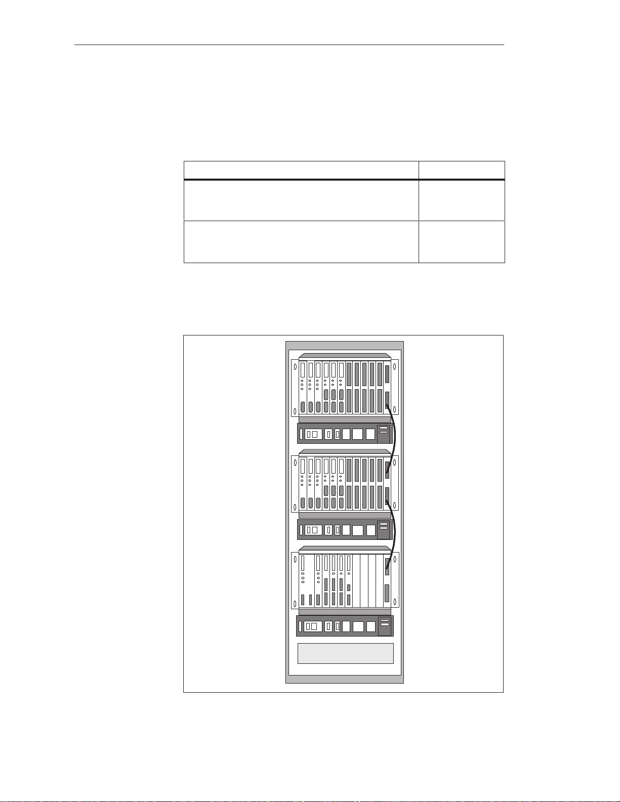
With the centralized configuration, you can install the CC and EUs in the
same cabinet or in adjacent cabinets. Data transmission is parallel. Shown in
the following figure is a centralized configuration.
EU
System Manual
C79000-G8576-C199-06
EU
CC
Load Power Supply
Figure 2-1 Centralized Configuration
2-3

Centralized and Distributed Configuration of a Programmable Controller
With the distributed configuration, a distinction is made between parallel and
serial communication. The main features of these types of communication
are as follows:
S Parallel fast data transmission line length of up to 600 m
S Serial slower data transmission line length of up to 3000 m
2.2.1 Installing a PLC with Centralized Configuration
The following table shows which interface modules and connecting cables
can be used for connecting the various expansion units to the CC in a
centralized configuration.
Interface Module
Expansion Unit Interface Module
in the CC
IM 300-3
6ES5 300-3AB11
EU 183U
EU 185U
IM 312-3
6ES5 312-3AB11
(I/O mod. only)
IM 301-3 1)
6ES5 301-3AB13
EU 183U
EU 185U
IM 312-3
6ES5 312-3AB31
(I/O mod. only)
IM 300-5
6ES5 300-5CA11
IM 301-5
1)
6ES5 301-5CA12
IM 300-5
6ES5 300-5LB11
1)
This IM has a second interface for distributed communication.
2)
The last IM 312-3 always requires a 6ES5 760-0AB11 terminator .
EU 184U
EU 187U
EU 184U
EU 187U
IM 312-5
6ES5 312-5CA11
IM 312-5
6ES5 312-5CA21
ER 701-1 IM 306
6ES5 306-7LA11
in the EU
2)
2)
Connecting Cable
Max. Distance
fixed to the IM 312 module
0.5 m; 0.95 m
fixed to the IM 312 module
0.5 m; 0.95 m
fixed to the IM 312 module
0.5 m; 1.5 m
fixed to the IM 312 module
0.5 m; 1.5 m
6ES5 705-0xxxx
0.5 m to 2,5 m
2-4
To install a PLC in a centralized configuration, you must observe the
following conditions:
S A centralized configuration is generally only suitable for connecting I/O
modules (DI, DO, AI, AO) and some intelligent I/O modules (IPs) in the
EU (see the Configuring Aids in the catalog and Chapter 4).
S The line length between the IM in the CC and the last IM in the EU must
not exceed 2 m.
C79000-G8576-C199-06
System Manual
pp
Centralized and Distributed Configuration of a Programmable Controller
2.2.2 Installing a PLC with Distributed Configuration
To install a PLC in a distributed configuration, you have a choice of
parallel/symmetrical and serial communication. The following table shows
which interfaces and connecting cables can be used to connect the various
expansion units (EUs/ERs) to the CC in a distributed configuration.
Interface Module
in the CC
IM 301-3
6ES5 301-3AB13
(not for S5-155H)
IM 301-5
6ES5 301-5CA12
IM 304
6ES5 304-3UB11
IM 308
6ES5 308-3UA12
IM 308-B
6ES5 308-3UB11
IM 307
6ES5 307-3UA11
Expansion Unit Interface Module in
the EU
EU 183U
ER 701-2
ER 701-3
EU 183U
EU 185U
ER 701-2
ER 701-3
EU 183U
EU 185U
ER 701-2
ER 701-3
EU 183U
EU 185U
ET 100U
(Catalog ST 52.1)
ICM 560 –
ET 200 IM 318-B
ER 701-2
ER 701-3
EU 183U
EU 185U
1)
IM 310
6ES5 310-3AB11
1)
IM 310
6ES5 310-3AB11
1)
IM 314
6ES5 314-3UA11
IM 318-3
6ES5 318-3UA11
IM 318-8
6ES5 318-8MA12
6ES5 318-8MB11
IM 317
6ES5 317-3UA11
IM 317
6ES5 317-3UA11
Connecting Cable
Max. Permiss. Line Length
6ES5 721-0xxxx
1 m to 200 m
6ES5 721-0xxxx
1 m to 600 m
6ES5 707-5AA00
V45551-F21-B5
up to 3000 m
Cable connection
6ES5 722-2xxxx
Fiber optic cable up to 1500 m
1)
The last IM 310 or IM 314 always requires a 6ES5 760-1AA11 terminator.
System Manual
C79000-G8576-C199-06
The ER 701-2 and ER 701-3 always additionally require an IM 306 for
communication via an IM 304, IM 307 or IM 308.
To install a PLC in a distributed configuration, you must observe the
following conditions:
S With the IM 301/IM 310 pair of interface modules, you can only use I/O
modules (DI, DO, AI, AO) and IPs without page addressing in the EUs.
S With the IM 304/314 pair of interface modules, you can use all IPs, CPs
and I/O modules in the EU 185U.
Note
The IM 307/317, IM 308/318 and IM 308-B/318-B each have their own
manual (see catalog).
2-5
Centralized and Distributed Configuration of a Programmable Controller
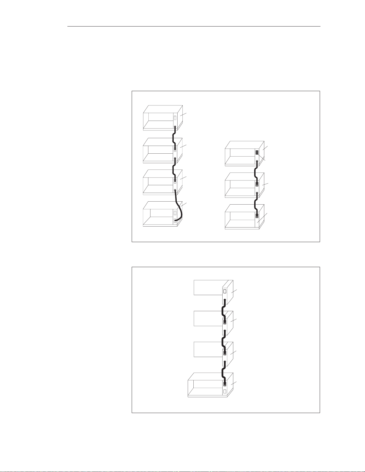
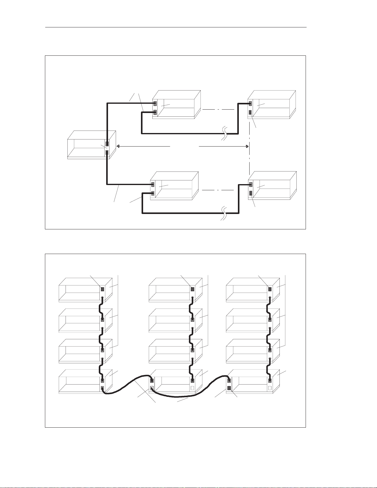
2.3 Examples
Given in the following are some examples of centralized and distributed
configuration of various SIMATIC S5 components.
3 EUs max.
EU 184U
EU 184U
EU 184U
CC S5-135U/155U
IM 312-5
IM 312-5
IM 312-5
IM 300-5
4 EUs max.
EU183U
EU183U
CC S5-135U/155U
IM 312-3
6ES5 760-0AB11
IM 312-3
IM 300-3
Figure 2-2 Centralized Configuration of an S5-135U/155U with the IM 300
and IM 312
3 ERs max.
2-6
ER 701-1
ER 701-1
ER 701-1
IM 306
IM 306
IM 306
IM 300-5LB
CC S5-135U/155U
Figure 2-3 Centralized Configuration of an S5-135U/155U with ER 701s
C79000-G8576-C199-06
System Manual
IM 304
CC S5-135U/155U
Centralized and Distributed Configuration of a Programmable Controller
6ES5 721-0xxx0
EU185U
IM 314
600m max.
4 EUs max.
EU 185U
IM 314
6ES5 760-1AA11
EU185U
IM314
6ES5 721-0xxx0
Figure 2-4 Distributed Configuration of an S5-135U/155U with the IM 304 and IM 314
6ES5 760-0AB11
EU 183U
EU 183U
EU 183U
IM 312-3 IM 312-3
6ES5 760-0AB11
EU 183U
EU 183U
EU 183U
4 EUs max.
6ES5760-0AB11
EU 183U
EU 183U
EU 183U
EU 185U
IM 314
6ES5 760-1AA11
IM312-3
IM 300-3
IM 310-3
EU 183U
6ES5 760-0AA11
CC S5-135U/155U
IM 301-3
IM 310-3
EU 183U
6ES5 721-0xxx0
Figure 2-5 Distributed Configuration of an S5-135U/155U with Expansion Units in Centralized Configuration
System Manual
C79000-G8576-C199-06
IM 300-3
2-7

Centralized and Distributed Configuration of a Programmable Controller
2-8
C79000-G8576-C199-06
System Manual

Installation Guidelines
The Installation Guidelines provide you with information for the
interference-free installation of the SIMATIC S5-135U/155U programmable
controllers.
This chapter describes the following:
Paths which serve for interference pickup in programmable controllers,
and five rules for ensuring electromagnetic compatibility (EMC)
Interference-free installation of the programmable controllers
Cable routing, the connecting of cable shields and equipotential bonding
between equipment
The power supplies for control and load circuits, and the different
grounding concepts
Shielding and grounding for the connection of centralized and distributed
expansions and monitors to programmable controllers
The selection and design of cabinets
3
Chapter
Overview
Section Description Page
3.1 Principles of Installation of Systems for EMC 3-2
3.2 Installation of Programmable Controllers for EMC 3-8
3.3 Wiring of Programmable Controllers for EMC 3-12
3.4 Power Supplies for Programmable Controllers and I/Os 3-20
3.5 Interference-Free Installation of Centralized and
Distributed Interface Circuits
3.6 Interference-Free Connection of Monitors 3-30
3.7 Selection and Installation of Cabinets with SIMA TIC S5 3-33
3-28
System Manual
C79000-G8576-C199-06
3-1
Installation Guidelines
3.1 Principles of Installation of Systems for EMC
What Does EMC
Mean?
Electromagnetic compatibility (EMC) is understood to mean the capability of
electrical equipment to operate correctly in a defined electromagnetic
environment, without being affected by the environment and without
affecting the environment to an unacceptable degree.
All SIMATIC S5 products have been developed for applications in harsh
industrial environments and meet high requirements for EMC. Before
installing the control system, however, you should still carry out EMC
planning and involve possible interference sources in the assessment.
Described in the following chapter are
the various paths over which interference can be picked up in the PLC,
typical interference sources and their coupling mechanisms,
basic rules for ensuring EMC.
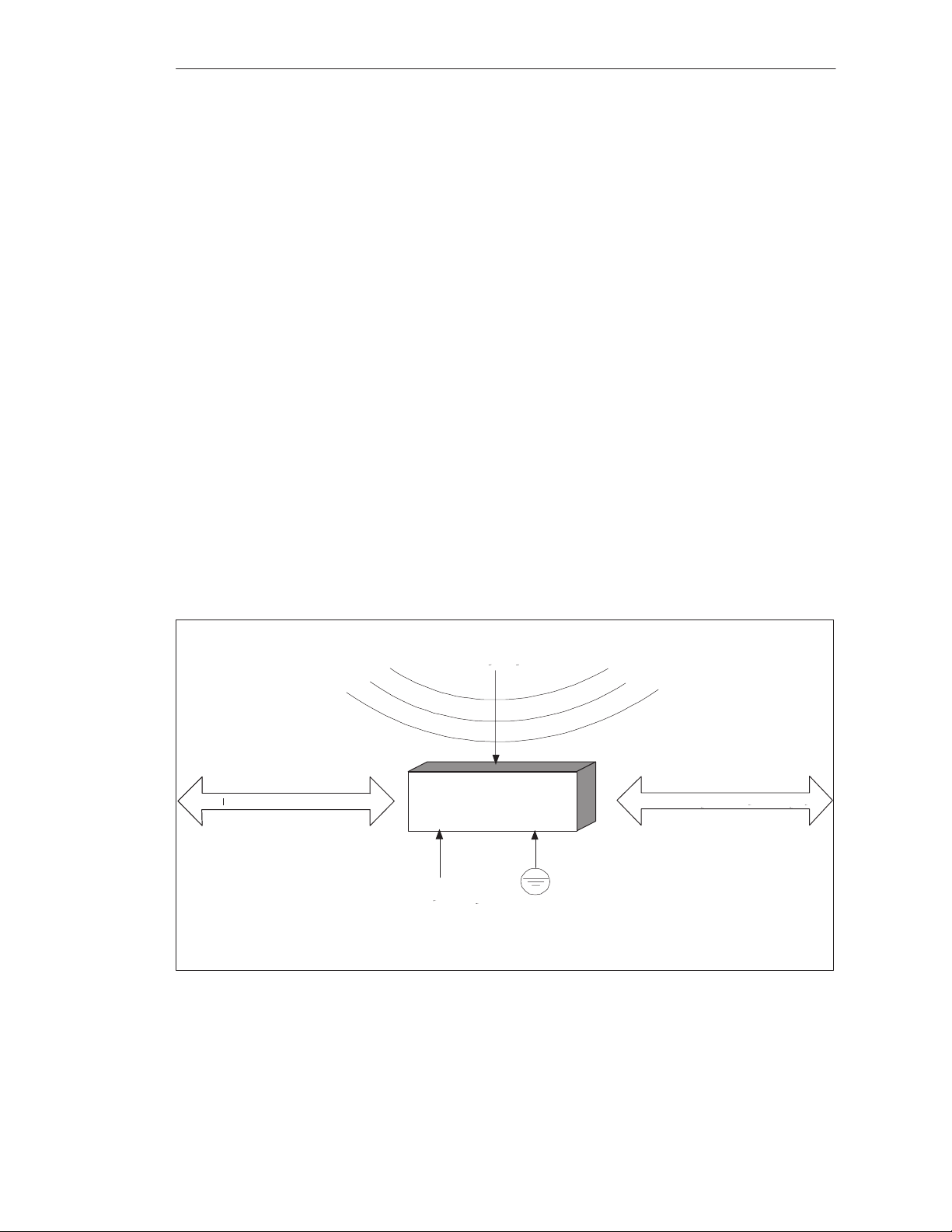
3.1.1 Overview of Possible Types of Interference
Electromagnetic interference can be picked up over different paths by the
programmable controller:
Fields
SINEC Bus System
Programmable
Controller
Power Supply
Protective Conductor
Figure 3-1 Electromagnetic Interference with Programmable Controllers
3-2
I/O Signal Lines
C79000-G8576-C199-06
System Manual

Installation Guidelines
Depending on the propagation medium (conducted or non-conducted
interference) and distance from the source, interference can be picked up by
the programmable controller via different coupling mechanisms.
A distinction is made between the following:
Direct coupling
Capacitive coupling
Inductive coupling
Radiated interference
System Manual
C79000-G8576-C199-06
3-3
s
g
Installation Guidelines
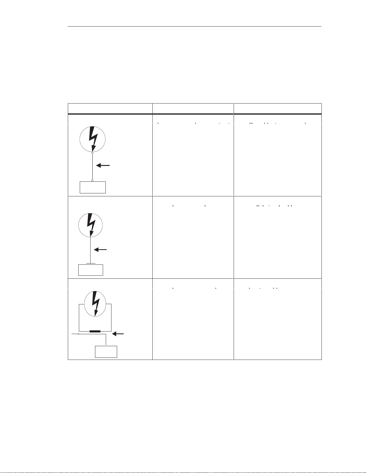
Coupling
Mechanisms and
Shown in the following table are the four different coupling mechanisms,
their causes, and possible interference sources.
Typical
Interference
Sources at a
Glance
Coupling Mechanism Cause Typical Interference Sources
Direct Coupling Direct or metallic coupling
always occurs when two circuit
Interference
have a common conductor
Switched devices (supply
affected by inverters and
external power supply units)
Motors being started
Different potentials of
component cases with a
common power supplys
Static discharges
SIMATIC S5
Direct Coupling
Path
Capacitive Coupling Capacitive or electrical coupling Interference pickup via
Interference
Capacitive Coupling
Path
occurs between conductors
which are at different potentials.
The degree of coupling is
proportional to the voltage
variation as a function of time.
parallel signal cables
Static discharge of the
operator
Contactors
SIMATIC S5
Inductive Coupling Inductive or magnetic coupling
occurs between two conductor
Signal
3-4
Interference
Inductive
Coupling Path
SIMATIC S5
loops through which current is
flowing. Interference voltages
are induced by the magnetic
fluxes associated with the
currents. The degree of couplin
is proportional to the current
variation as a function of time.
Transformers, motors,
electric welders
Parallel AC supply cables
Cables whose currents are
switched⁄
Signal cables with a high
frequency
Unconnected coils
C79000-G8576-C199-06
System Manual
Loading...