


 Loading...
|
|
|
Communication modules |
|
|
|
|
7.1 8xIQ-Sense |
|
7.1.5 |
Technical data |
|
|
|
|
|
|
|
|
|
|
Voltages and currents |
|
|
|
|
Rated supply voltage |
24 V DC |
|
|
|
Reverse polarity protection |
yes |
|
|
|
Galvanic isolation |
|
|
|
|
• Between the channels |
no |
|
|
|
• Between channels and backplane bus |
yes |
|
|
|
Permissible potential difference |
|
|
|
|
Between different circuits |
75 V DC / 60 V AC |
|
|
|
Insulation tested at |
500 V DC |
|
|
|
Current input |
|
|
|
|
• from the backplane bus |
120 mA typical |
|
|
|
• from L+ power supply |
500 mA max. |
|
|
|
Module power loss |
2.5 W typical |
|
|
|
Module-specific data |
|
|
|
|
Number of channels |
8 |
|
|
|
Channels for RFID systems |
2 |
|
|
|
Cable length, unshielded |
50 m max. |
|
|
|
Dimensions and weight |
|
|
|
|
Dimensions w x h x d (mm) |
40 x 125 x 120 |
|
|
|
Weight |
Approx. 235 g |
|
7.1.6 |
Ordering data |
|
|
|
|
|
|
|
|
8xIQ-Sense |
Order No. |
|
|
SIMATIC S7-300 |
6ES7 3387XF000AB0 |
|
|
IQ-Sense SM338 for S7-300 and ET200M for the |
|
|
|
connection of up to 8xIQ-Sense sensors |
|
|
|
Optical sensors, ultrasonic sensors and RF |
|
|
|
identification systems can be connected. |
|
|
|
Accessories |
|
|
|
M12 cable plug, 4-pole, with 5 m black PUR |
3RX8000-0CB42-1AF0 |
|
|
cable, 4 x 0.34 mm2 |
|
|
|
M12 cable plug, 4-pole, with 10 m black PUR |
3RX8000-0CB42-1AL0 |
|
|
cable, 4 x 0.34 mm2 |
|
SIMATIC RF300 |
7-7 |
System Manual, Release 04/2006, J31069 D0166-U001-A2-7618 |

Communication modules 7.2 ASM 452
7.2ASM 452
7.2.1Features
Field of application
The ASM 452 interface module is a MOBY module for operating MOBY and RF300 components with RS 422 over PROFIBUS DP-V1 on
•Any computers and PCs
•Any PLCs
When operating the interface module on a SIMATIC S7, function blocks are made available to the user.
Figure 7-6 Interface module ASM 452
The ASM 452 is the result of consistent development of the familiar ASM 450/451 interface modules. Optimal data throughput can be achieved even in large-scale PROFIBUS configurations thanks to the use of acyclic data traffic on PROFIBUS DP V1. The minimum cyclic data load of the ASM 452 on the PROFIBUS provides the user with the guarantee that other PROFIBUS nodes (e.g. DI/DO) can still be processed at great speed.
The ASM 452 is an interface module for communication between PROFIBUS and the RF310R with RS 422 interface. Through the ASM 452, the data on the RF320T, RF340T, RF350T and RF360T transponders can be physically addressed ("Normal" addressing). In SIMATIC S7, FC 45 is available for this purpose.
7-8 |
SIMATIC RF300 |
System Manual, Release 04/2006, J31069 D0166-U001-A2-7618 |
Communication modules 7.2 ASM 452
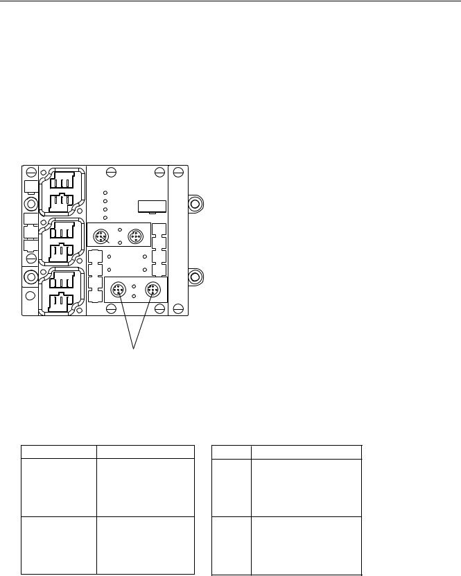
7.2.2Pin assignment and display elements
Pin assignments
The figure below illustrates the pin assignments of ASM 452.
;
;
;
|
$60b |
|
|
|||
|
|
|
|
|
|
|
|
|
6) |
|
|
|
|
|
|
%) |
|
|
|
|
|
|
|
|
|
|
|
|
|
21 |
|
|
|
|
|
|
9 '& |
|
|||
|
; |
6/* |
; |
|
||
|
|
|
|
|
|
|
|
|
|
5[' |
|
|
|
|
|
35( (55 |
|
35( (55 |
|
|
|
|
|
|
|
|
|
|
|
|
|
|
|
|
|
|
; |
|
|
; |
|
|
|
|
|
6/* |
|
|
|
|
|
|
|
5[' |
|
|
|
|
|
|
|
|
1RW DYDLODEOH IRU 5)
/('V IRU 352),%86 '3
6) |
6\VWHP )DXOW |
%) |
%XV )DXOW |
21 |
/LW ZKHQ ORJLF YROWDJH LV DSSOLHG |
RQ $60 JHQHUDWHG IURP
9 VXSSO\ YROWDJH
b9 '& /LW ZKHQ 9 VXSSO\ YROWDJH LV DSSOLHG
WR $60
/('V IRU 5) DQG $60
5[' 5HDGHU DFWLYH ZLWK FRPPDQG 35( (55 7UDQVSRQGHU SUHVHQW RU HUURU GLVSOD\35( (55 IRU UHDGHU
7KH WUDQVSRQGHU SUHVHQW GLVSOD\ DOZD\V
WDNHV SULRULW\ 7KH HUURU LV RQO\ LQGLFDWHG
ZKHQ D WUDQVSRQGHU LV QRW
SUHVHQW
7UDQVSRQGHU SUHVHQW
7KH /(' LV SHUPDQHQWO\ 21 ,I PRUH
WKDQ RQH WUDQVSRQGHU LV LQ WKH ILHOG WKH
QXPEHU
RI WKH WUDQVSRQGHU LV LQGLFDWHG ZLWK VKRUW
IODVKHV 1R
HUURU GLVSOD\
(UURU GLVSOD\
7KH /(' LV SHUPDQHQWO\ 2)) 7KH ODVW
HUURU QXPEHU LV LQGLFDWHG ZLWK
VKRUW IODVKHV
5HDGHU 5HDGHU LV VHOHFWHG5HDGHU 5HDGHU LV VHOHFWHG
2QO\ UHDGHU FDQ EH VHOHFWHG
6RFNHW |
3LQ DVVLJQPHQW |
|
; DQG ; |
|
6LJQDO % UHG |
352),%86 '3 |
|
3( |
|
|
3( |
|
|
6LJQDO $ JUHHQ |
|
|
/ |
|
|
0 |
; |
|
3( |
6XSSO\ |
|
/ |
YROWDJH |
|
0 |
|
|
3( |
|
|
/ |
|
|
0 |
1RW FRQQHFWHG
Figure 7-7 Pin assignment and LEDs of ASM 452
6RFNHW 3LQ DVVLJQPHQW UHDGHU
; ; |
|
5[' |
|
|
|
7[' |
|
|
|
7[' |
|
|
|
5[' |
|
|
|
3( |
|
; ; |
|
; |
; |
|
|
9 9 |
|
|
|
'2 |
', |
|
|
9 |
9 |
|
|
'2 |
', |
|
|
3( |
3( |
SIMATIC RF300 |
7-9 |
System Manual, Release 04/2006, J31069 D0166-U001-A2-7618 |
Communication modules 7.2 ASM 452
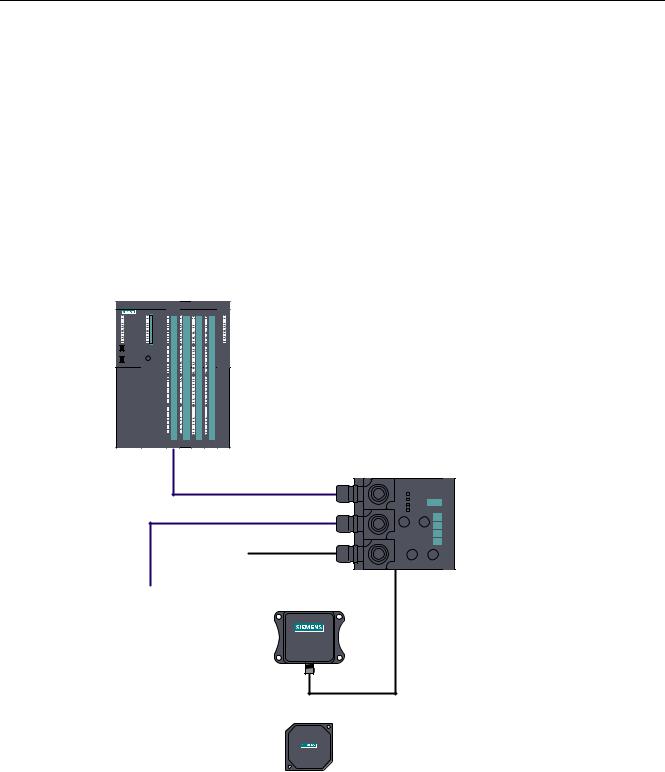
7.2.3Configuration
Configuration
Hardware description
The ASM 452 has the same housing as the distributed I/O system ET 200X. General information on ASM 452 (e.g. assembly, operation and wiring; general technical data) is available in the ET200X manual (Order No. 6ES7 198-8FA00-8AA0). Descriptions of accessories and network components can also be found in this manual.
Configuration
352),%86 '3 PDVWHU PRGXOH |
H J 6 &38 |
352),%86 FDEOHV
9 IRU $60
WR RWKHU |
|
352),%86 |
|
|
5) [[5 |
QRGHV |
|
|
6,0$7,& |
|
5) 5 |
6,0$7,&
5) 7
5) [[7
Figure 7-8 ASM 452 configurator
7-10 |
SIMATIC RF300 |
System Manual, Release 04/2006, J31069 D0166-U001-A2-7618 |
Communication modules 7.2 ASM 452
PROFIBUS configuration
The ASM 452 is integrated into the hardware configuration by means of a GSD file. The ASM can then be configured using the HW Config of SIMATIC Manager or another PROFIBUS tool.
A GSD file is provided for ASM 452 on the CD "RFID Systems Software & Documentation".
Operating mode of the ASM 452
The approved operating modes of ASM 452 are described in the GSD file. It is set using the hardware configuration tool (e.g. STEP 7 HW Config).
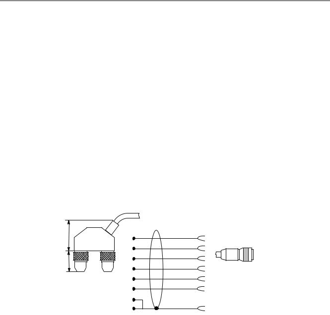
Reader connection system
A reader always occupies two M12 connector sockets on the ASM 452.
A pre-assembled cable therefore ensures easy connection of the reader (see figure below). The connecting cable is available in lengths of 2 m (standard) and 5 m. Extensions are possible up to 1000 m using connecting cables 6GT2891-… .
$60 VLGH |
|
|
5HDGHU VLGH |
|
|
|
|
JUHHQ |
|
|
|
; |
|
|
|
|
|
ZKLWH |
|
|
|
; |
|
|
|
|
|
EURZQ |
|
|
|
; |
|
|
|
|
|
|
|
|
|
|
\HOORZ |
|
|
|
; |
|
0 SLQ |
; |
; |
; |
SLQN |
|
7ZR SLQ 0 |
|
|
|
|
|
|
|
JUD\ |
|
FLUFXODU FRQQHFWRUV |
; |
|
|
|
|
|
; |
|
|
|
|
|
VKLHOG |
|
|
|
; |
|
|
Figure 7-9 Connecting cable (2 m) ASM 452/473 ↔ RF310R reader with RS 422 (6GT2891-1CH20)
SIMATIC RF300 |
7-11 |
System Manual, Release 04/2006, J31069 D0166-U001-A2-7618 |

Communication modules 7.2 ASM 452
Cable installation
Signal |
M12 (reader side) |
Cable |
|
X1 / Data |
X2 |
24 V DC |
1 |
Pink |
- |
1 |
|
TX - |
2 |
Yellow |
4 |
- |
|
GND |
3 |
Gray |
- |
3 |
|
TX + |
4 |
Green |
1 |
- |
|
RX + |
5 |
white |
2 |
- |
|
RX - |
6 |
brown |
3 |
- |
|
- |
|
|
- |
- |
|
Shield |
8 + terminal piece |
Shield |
5 |
5 |
|
Cable installation ASM 452/473 ↔ RF310R reader with RS 422 (6GT2891-1CH20)
A reader cable connector with screw-type terminals is provided for users who want to individually pre-assemble their own cables (see figure below). Cables and reader cable connectors can be ordered from the MOBY catalog.
|
$60 FDEOH *7 |
|
3* FDEOH JODQG |
|
PD[ FDEOH GLDPHWHU |
|
PP RQO\ VFUHZ GRZQ |
|
DIWHU DVVHPEOLQJ WKH |
|
|
|
FRQQHFWRU |
|
VFUHZV |
|
IRU RSHQLQJ |
|
WKH FRQQHFWRU |
|
|
'HJUHH RI SURWHFWLRQ ,3 &RQQHFWRU 0 WR $60
&RQQHFWRU FRYHU UHPRYHG
6
6
Figure 7-10 Cable connector ASM 452/473 ↔ RF310R reader with RS 422 (6GT2090-0BC00)
Pin assignment for ASM 452/473 cable connector
Connector pin |
Connection to pin of the reader |
Wire color |
1 |
4 |
Note data sheet provided by the |
2 |
5 |
manufacturer |
|
||
3 |
6 |
|
4 |
2 |
|
5 |
3 |
|
6 |
1 |
|
|
- |
|
S |
8 + terminal piece |
|
Pin 7 must not be connected.
7-12 |
SIMATIC RF300 |
System Manual, Release 04/2006, J31069 D0166-U001-A2-7618 |

Communication modules 7.2 ASM 452
PROFIBUS cable with 24 V supply
The ASM 452 can also be operated with the "green" PROFIBUS cable. It is important to ensure that a 24 V cable is connected from X12 to X13. The 24 V cable can be connected to pins 5 and 6 in plug X12.
|
; |
|
; |
|
; |
|
; |
; |
|
; |
|
Figure 7-11 PROFIBUS cable with 24 V supply
PROFIBUS address and terminating resistor
You must remove the connector plate from the ASM before you set the
PROFIBUS address or connect the terminating resistor. The connector plate covers the DIL switch. The position of the DIL switch in ASM is shown in the figure below with one setting example for each case.
([DPSOH 7HUPLQDWLQJ UHVLVWRU 2II$V GHOLYHUHG VWDWH
RQ
2II

([DPSOH 352),%86 DGGUHVV RQ GHOLYHU\
21 


6WDQGDUG PRGHXVH *6' ILOH 6,(0 %
Figure 7-12 Setting the PROFIBUS address/connecting the terminating resistor
Note
•The PROFIBUS address in ASM 452 must always match the PROFIBUS address defined in the configuring software for this ASM.
•To ensure that the terminating resistor functions correctly, you must always switch both DIL switches of the terminating resistor to "on" or "off".
SIMATIC RF300 |
7-13 |
System Manual, Release 04/2006, J31069 D0166-U001-A2-7618 |

Communication modules 7.2 ASM 452
7.2.4Technical data
Technical data
Table 7-2 |
Technical data for ASM 452 |
|
|
|
|
|
|
ASM 452 with FC 45 |
Serial interface to the user |
PROFIBUS DP-V1 |
|
Procedure after connection |
EN 50170 Vol. 2 PROFIBUS |
|
|
|
PG 11 cable gland |
|
|
PROFIBUS and power supply connectors are not included |
|
|
in the scope of delivery |
Transmission rate |
9600 baud to 12 Mbaud (automatic detection) |
|
Max. block length |
2 words cyclic/240 bytes acyclic |
|
Serial interface to the RF3xxR |
|
|
Connector |
|
2 x M12 coupler plug |
Max. cable length |
2 m = Standard length, 5 m, 10 m, 20 m and 50 m, |
|
|
|
(up to 1000 m on request) |
Readers that can be connected |
1x RF3xxR with RS 422 interface |
|
Software functions |
|
|
Programming |
Depending on the PROFIBUS DP master |
|
Function blocks for SIMATIC S7 |
FC 45 |
|
Transponder addressing |
Direct access via addresses |
|
Commands |
|
Initialize transponder, read data from transponder, write |
|
|
data to transponder |
Multi-tag capability |
No |
|
S7 data structures via UDTs |
Yes |
|
Power supply |
|
|
Rated value |
|
24 V DC |
Permissible range |
20 V to 30 V DC |
|
Current consumption |
Max. 180 mA; typ. 130 mA (without reader) |
|
Digital inputs |
|
none |
Digital outputs |
none |
|
Ambient temperature |
|
|
During operation |
0 °C to +55 °C |
|
Storage and transport |
-40 °C to +70 °C |
|
Dimensions (W x H x D) in mm |
134 x 110 x 55 (without bus connector) |
|
Fixing |
|
4 M5 screws; |
|
|
for mounting on any plate or wall |
Weight, approx. |
0,5 kg |
|
Degree of protection |
IP67 |
|
MTBF (at 40 °C) |
30 • 104 hours = 34 years |
|
7-14 |
SIMATIC RF300 |
System Manual, Release 04/2006, J31069 D0166-U001-A2-7618 |

Communication modules 7.2 ASM 452
7.2.5PROFIBUS Diagnosis
PROFIBUS Diagnosis
The following table lists possible error indications with their meanings and provides remedies.
Table 7-3 |
LED indication for PROFIBUS diagnosis |
|
|
||
|
|
|
|
|
|
"BF" LED |
|
"SF"LED |
Cause of error |
|
Error correction |
ON |
|
* |
• ASM 452 is in start-up mode. |
- |
|
|
|
|
• The connection to the DP master |
|
• Check the PROFIBUS DP |
|
|
|
has failed. |
|
connection. |
|
|
|
• ASM 452 not detecting a baud |
|
• Check the DP master. |
|
|
|
rate. |
|
|
|
|
|
• Bus interrupt |
|
• Check all cables on your |
|
|
|
• DP Master not functioning |
|
PROFIBUS DP network. |
|
|
|
|
|
• Check whether the connector |
|
|
|
|
|
plugs for PROFIBUS DP are |
|
|
|
|
|
securely plugged into the |
|
|
|
|
|
ASM 452. |
flashes |
|
ON |
• The configuration data sent to |
|
• Check the configuration of |
|
|
|
the ASM 452 by the DP master |
|
the ASM 452 (input/output, |
|
|
|
do not match the configuration of |
|
PROFIBUS address). |
|
|
|
the ASM 452. |
|
• Correct GSD file being used? |
|
|
|
|
|
– SIEM80B6.GSD for |
|
|
|
|
|
ASM 452 |
flashes |
|
Off |
• ASM 452 has detected the baud |
|
• Check the PROFIBUS |
|
|
|
rate, but is not being addressed |
|
address set on the ASM 452 |
|
|
|
by the DP Master. |
|
or in the configuration |
|
|
|
• ASM 452 has not been |
|
software. |
|
|
|
configured. |
|
• Check the configuration of |
|
|
|
|
|
the ASM 452 (station type). |
ON |
|
flashes |
• There is a hardware defect in the |
|
• Replace the ASM 452. |
|
|
|
ASM 452. |
|
|
SIMATIC RF300 |
7-15 |
System Manual, Release 04/2006, J31069 D0166-U001-A2-7618 |

Communication modules 7.2 ASM 452
7.2.6Dimensional drawings
Dimension drawing
The following figure shows the dimensional drawing of an ASM 452 with bus connectors. You must add the length of the PG cable gland and the radius of the cable used to the measured overall width and depth.
|
|
|
|
|
|
|
|
|
|
|
|
Figure 7-13 Dimensional drawing of ASM 452
Example of stripped lengths
The following diagram shows an example of stripped lengths. The lengths apply to all cables which can be connected to the connector plugs. You must twist any shield braid present, plug into a core end sleeve and cut off any excess.
7ZLVWHG DQG
WUXQFDWHG VKLHOG EUDLGLQJ
Figure 7-14 Length of stripped insulation for PROFIBUS cables
7-16 |
SIMATIC RF300 |
System Manual, Release 04/2006, J31069 D0166-U001-A2-7618 |
Communication modules 7.2 ASM 452
7.2.7Ordering data
Ordering data
Table 7-4 |
Ordering data for ASM 452 and accessories |
|
|
|
|
Product description |
Order No. |
|
ASM 452 interface module for PROFIBUS DP-V1, 1x RF310R with |
6GT2002-0EB20 |
|
RS 422 interface, without connector for 24 V DC and PROFIBUS |
|
|
Accessories: |
|
|
Connector for PROFIBUS DP and 24 V supply |
6ES7194-1AA00-0XA0 |
|
Connecting cable RF310R ↔ ASM 452 |
|
|
Plug-in cable, pre-assembled, length: 2 m (standard length) |
6GT2891-1CH20 |
|
Plug-in cable, pre-assembled, length: 5 m |
6GT2891-1CH50 |
|
Opt. Cable connector without read/write device cable |
6GT2090-0BC00 |
|
(for cable lengths > 20 m) ASM 452 ↔ reader |
|
|
M12 blanking cap for unused RF310R connection (1 pack = |
3RX9802-0AA00 |
|
10 pieces) |
|
|
CD "RFID Systems Software & Documentation" with FC 45, GSD |
6GT2080-2AA10 |
|
file |
|
|
Replacement part: |
|
|
Connector plate; T functionality for PROFIBUS connection |
6ES7194-1FC00-0XA0 |
|
FC 45 Reference Manual |
|
|
German |
|
Available in electronic form on |
English |
|
the CD "RFID Systems |
French |
|
Software & Documentation" |
The ASM 456 plug-in cables 6GT2891-0Fxxx can be used as extension cables.
SIMATIC RF300 |
7-17 |
System Manual, Release 04/2006, J31069 D0166-U001-A2-7618 |
Communication modules 7.3 ASM 456
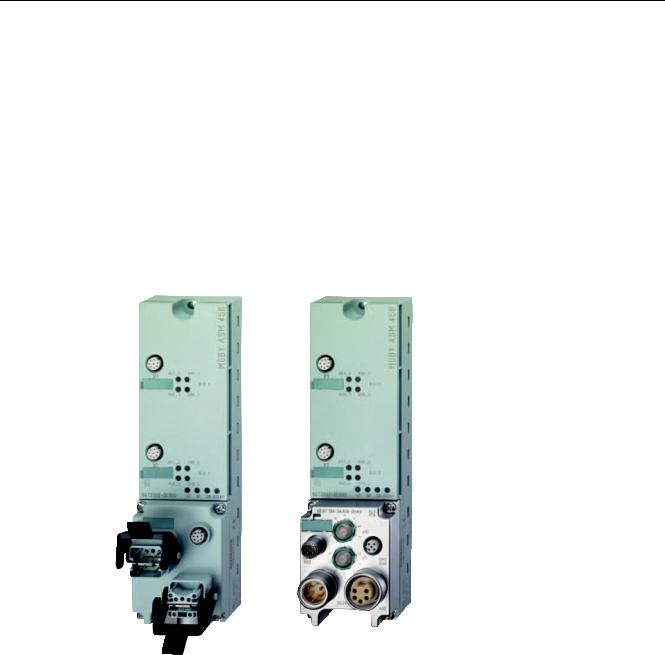
7.3ASM 456
7.3.1Description
Field of application
The ASM 456 interface modules are slave modules for operating RF300 components via the PROFIBUS DP/DP-V1 on any control systems.
Figure 7-15 Interface module ASM 456 with ECOFAST connection block or M12, 7/8"
When operating the interface module on a SIMATIC S7, convenient function blocks are made available to the user.
7-18 |
SIMATIC RF300 |
System Manual, Release 04/2006, J31069 D0166-U001-A2-7618 |

Communication modules 7.3 ASM 456
Features
The ASM 456 replaces the ASM 452 in terms of functionality and provides a simplified connection system. You can continue to use the user software from ASM 452. Optimum data throughput can be achieved through acyclic data traffic on the PROFIBUS DP V1 even when using large PROFIBUS configurations. The minimum cyclic data load of the ASM 456 on the PROFIBUS provides the user with the guarantee that other PROFIBUS consumers (e.g. DI/DO) can still be processed at great speed.
Up to 2 readers can be operated in parallel on the ASM 456. The user can start a command in parallel on 2 readers (via the corresponding FB/FC).
The transponder data are accessed by means of physical addressing of the reader. In SIMATIC S7, the FC 45 is available for this purpose. The FC 45 provides the S7 user with a simple-to-use interface with powerful commands (processing one complete transponder with one command; command linking; S7 data structures via UDTs).
Other features
•Degree of protection IP67
•System integration with ECOFAST or M12, 7/8" concept
•T functionality, that is, a component can be replaced without adversely affecting other modules with regard to bus communication and voltage supply
•Standardized PROFIBUS user interface for identification systems with PIB (Proxy Ident Function Block; with later firmware version).
•Firmware update
•PROFIBUS interface module up to 12 Mbaud with automatic baud rate detection
•Parameterizable device-related diagnostics data with text display
•Support for I&M functionality (a mechanism for reading out information via the module and saving system information such as function, installation date, installation location, and comments.)
SIMATIC RF300 |
7-19 |
System Manual, Release 04/2006, J31069 D0166-U001-A2-7618 |

Communication modules 7.3 ASM 456
Design
The ASM 456 has the same housing as the distributed I/O system ET 200eco.
The ASM has a connection block for connecting up to the PROFIBUS DP which is available as an option and the ECOFAST version or M12, 7/8".
The following figure shows the basic design of the ASM 456.
;
;
*7 ('
02%<$60
&RQQHFWRU VRFNHW IRU VW UHDGHU
6WDWXV /('V IRU RSHUDWLRQ RI WKH VW UHDGHU
&RQQHFWRU VRFNHW IRU QG UHDGHU
6WDWXV /('V IRU RSHUDWLRQ RI WKH QG UHDGHU
6WDWXV /('V IRU LQWHUIDFH PRGXOH 5HDGHU
6SDFH IRU FRQQHFWLRQ EORFN
3URWHFWLYH HDUWK
Figure 7-16 Basic design of the ASM 456
7-20 |
SIMATIC RF300 |
System Manual, Release 04/2006, J31069 D0166-U001-A2-7618 |

Communication modules 7.3 ASM 456
Configuration
The following figure shows how the ASM 456 is integrated in an automation system.
352),%86 '3 PDVWHU PRGXOH |
H J 6 &38 |
$60b |
; |
|
; |
|
352),%86 FDEOHV |
|
|
P |
9 IRU $60 |
|
DQG UHDGHU |
|
WR RWKHU |
|
352),%86 QRGHV |
|
6,0$7,& |
6,0$7,& |
5) 5 |
5) 5 |
5HDGHU |
5HDGHU |
6,0$7,& |
6,0$7,& |
5) 7 |
5) 7 |
6WDQGDUG FDEOH OHQJWK |
|
7UDQVSRQGHU |
|
Figure 7-17 ASM 456 configurator
The ASM 456 is integrated into the hardware configuration by means of a GSD file. The ASM can then be configured using HW Config of SIMATIC Manager or another PROFIBUS tool (e.g. operating mode). The GSD file can be found on the "RFID Systems Software & Documentation" CD or on the Internet.
SIMATIC RF300 |
7-21 |
System Manual, Release 04/2006, J31069 D0166-U001-A2-7618 |

Communication modules 7.3 ASM 456
7.3.2Setting the PROFIBUS address
Features
The PROFIBUS address defines the address at which the ASM 456 distributed I/O system is found on the PROFIBUS DP.
Requirements
•The PROFIBUS DP address for the ASM 456 is set on the connection block.
•Each address can be assigned only once on the PROFIBUS DP.
•The PROFIBUS address set must match the PROFIBUS address defined in the configuring software (for the ASM 456).
•Changes to the PROFIBUS DP address only take effect once the mains have been switched ON on the ASM 456.
Tools required for M12, 7/8” connection block
•Socket wrench 14 mm
•Screwdriver with 2.5 mm blade
7-22 |
SIMATIC RF300 |
System Manual, Release 04/2006, J31069 D0166-U001-A2-7618 |

Communication modules 7.3 ASM 456
Setting PROFIBUS DP addresses on connection block M12, 7/8”
Valid PROFIBUS DP addresses are 1 to 99.
1.Remove the two seal caps from the rotary switches (if necessary, use a 14 mm socket wrench).
2.Set the required PROFIBUS address on the rotary switches using a screwdriver.
–Lower rotary switch: 1st position
–Upper rotary switch: 10th position
3.Screw the two seal caps back onto the rotary switches (torque: 0.5 Nm to 0.8 Nm.)
[
|
|
|
|
|
|
|
|
|
[ |
|
|
|
|
|
|
([DPSOH 352),%86 DGGUHVV
|
[ |
|
|
|
|
|
|
|
|
|
3RVLWLRQ |
|
|
|
|
|
|
|
[ |
|
|
|
|
|
|
|
|
|
3RVLWLRQ |
|
|
|
5RWDU\ VZLWFK IRU 352),%86 DGGUHVV
Figure 7-18 Setting PROFIBUS addresses on connection block M12, 7/8”
SIMATIC RF300 |
7-23 |
System Manual, Release 04/2006, J31069 D0166-U001-A2-7618 |

Communication modules 7.3 ASM 456
Setting PROFIBUS DP addresses on connection block ECOFAST
Valid PROFIBUS DP addresses are 1 to 99.
1. Loosen the screw connection of the configuration plug with the ECOFAST connection block and remove the plug.
Figure 7-19 Loosening the configuration plug's screw connection
2.Loosen the screw connection for the cover cap on the configuration plug and remove the latter.
3.Set the PROFIBUS address using the DIL switches.
([DPSOH 352),%86 DGGUHVV
|
|
|
|
|
|
|
|||
|
|
|
|
|
|
|
21 |
|
21 |
|
|
|
||
Figure 7-20 Setting PROFIBUS address on configuration plug
4. Screw the cover cap back down, plug the configuration plug onto the connection block and screw the configuration plug to the connection block.
7-24 |
SIMATIC RF300 |
System Manual, Release 04/2006, J31069 D0166-U001-A2-7618 |

Communication modules 7.3 ASM 456
7.3.3Wiring up ASM 456
Wiring ECOFAST connector plugs
The table below contains the connector assignment for the ECOFAST connector plugs
Table 7-5 |
Connection assignment for ECOFAST connector plugs |
|
|
|
|
Pin |
Assignment |
View of ECOFAST connector plug |
|
|
(wiring end for supply and loop-through |
|
|
connection) |
APROFIBUS DP signal A
B |
PROFIBUS DP signal B |
|
|
|
|
6LJQDO $ |
|
|
|
|
|
||
1 |
Electronics / encoder supply (1L+) |
|
|
|
|
6LJQDO % |
$ |
% |
|
|
|
||
|
(voltage supply for ASM 456 and reader) |
|
|
|
|
|
|
|
|
|
|
(&2)$67 K\EULG FDEOH |
|
2 |
Ground for electronic / encoder supply |
|
|
|
|
|
|
|
|
|
|
||
|
(1M) |
|
|
|
|
|
|
|
|
|
|
/ |
|
3 |
Ground for load voltage supply (2M) |
|
|
|
|
|
4 |
Load voltage supply (2L+) |
|
|
|
|
|
|
|
|
|
|
|
|
|
|
|
|
|
/ |
|
|
(unused on ASM 456) |
|
|
|
|
|
|
|
|
|
|
|
|
*) You will find the assembly instructions in the packaging of the Han Brid Cu cable connector and/or Han Brid Cu cable socket.
SIMATIC RF300 |
7-25 |
System Manual, Release 04/2006, J31069 D0166-U001-A2-7618 |

Communication modules 7.3 ASM 456
Wiring M12, 7/8” connector
The tables below contain the connector assignment for the M12, 7/8” connector:
Table 7-6 |
Connection assignment for M12 connector (PROFIBUS DP) |
|
|
|
|
Pin |
Assignment |
View of M12 connector |
|
|
(wiring side) |
1Supply positive (P5V2) *
|
|
|
|
||
2 |
Data line A (RxD / TxD-N) |
6XSSO\ '3 |
|
||
|
|
|
6LJQDO $ JUHHQ |
||
3 |
Data reference potential (M5V2) * |
|
|
|
|
4 |
Data line B (RxD / TxD-P) |
|
|
|
|
|
|
|
6KLHOG |
||
5 |
Shield |
|
|
|
|
|
|
|
|
||
Thread |
Shield |
|
|
|
6LJQDO % UHG |
|
|
/RRS WKURXJK |
%XV FDEOH |
||
|
|
|
|
|
FRUH VKLHOGHG |
|
|
FRQQHFWLRQ '3 |
|
||
|
|
|
|
|
6LJQDO $ JUHHQ |
|
|
|
|
|
|
|
|
|
|
|
6KLHOG |
|
|
|
|
|
|
|
|
|
|
|
6LJQDO % UHG |
*) Can only be used for the M12 terminating resistor. Looping the voltage through to the next connector via a 5-core cable is not permitted.
7-26 |
SIMATIC RF300 |
System Manual, Release 04/2006, J31069 D0166-U001-A2-7618 |
Communication modules 7.3 ASM 456
Table 7-7 Connection assignment for 7/8” connector (supply voltages)
Pin |
Assignment |
|
|
|
|
|
View of 7/8” connector |
||||||
|
|
|
|
|
|
|
|
|
|
(wiring side) |
|
|
|
1 |
Ground for load voltage supply (2M) |
|
|
|
|
|
|
|
|
|
|
|
|
2 |
Ground for electronic / encoder supply (1M) |
6XSSO\ ; |
|
|
|||||||||
|
|
|
|
|
|
|
|
|
|
|
|
||
3 |
PE |
|
|
|
|
|
|
|
|
|
|
|
|
|
|
|
|
|
|
|
|
|
|
|
|
||
|
|
|
|
|
|
|
|
|
|
|
|
/ |
|
4 |
Electronics / encoder supply (1L+) |
|
|
|
|
|
|
|
|
||||
|
(voltage supply for ASM 456 and reader) |
|
|
|
|
|
|
|
|
||||
|
|
|
|
|
|
|
|||||||
5 |
Load voltage supply (2L+) |
|
|
|
|
|
|
|
|
|
|
||
|
|
|
|
|
|
|
|
|
|||||
|
(unused on ASM 456) |
|
|
|
|
|
|
|
|
|
|
|
|
|
|
|
|
|
|
|
|
|
|
|
|
|
|
|
|
|
|
|
|
|
|
|
|
|
/ |
||
|
|
|
|
|
|
|
|
|
|
|
|
|
|
|
|
|
|
|
|
|
|
|
|||||
|
|
/RRS WKURXJK |
|
|
|||||||||
|
|
|
|
|
|
|
|
|
|
|
|
FRUH FDEOH |
|
|
|
FRQQHFWLRQ ; |
|
|
|||||||||
|
|
|
|
|
|
|
|
|
|
|
|
|
|
|
|
|
|
|
|
|
|
|
|
|
|
|
|
|
|
|
|
|
|
|
|
|
|
|
|
|
|
|
|
|
|
|
|
|
|
|
|
|
|
/ |
|
|
|
|
|
|
|
|
|
|
|||||
|
|
|
|
|
|
|
|
|
|||||
|
|
|
|
|
|
|
|
|
|
|
|
||
|
|
|
|
|
|
|
|
|
|
|
|
|
|
|
|
|
|
|
|
|
|
|
|
|
|
/ |
|
|
|
|
|
|
|
|
|
|
|
|
|
|
|
|
|
|
|
|
|
|
|
|
|
|
|
|
|
Note
When connecting up the supply voltage, we recommend that the cable 6XV1 822-5B... (5 x 1.5 mm2 pre-assembled with 7/8" connectors) is used.
If you want to assemble the cable yourself, then the conductor cross-section should be 1.5 mm2.
SIMATIC RF300 |
7-27 |
System Manual, Release 04/2006, J31069 D0166-U001-A2-7618 |
Loading...