


Programmable |
SAE 800 |
Single-/Dual-/Triple- Tone Gong |
|
Preliminary Data |
Bipolar IC |
Features
●Supply voltage range 2.8 V to 18 V
●Few external components (no electrolytic capacitor)
●1 tone, 2 tones, 3 tones programmable
● Loudness control
● Typical standby current 1 μA
●Constant current output stage (no oscillation)
●High-efficiency power stage
● |
Short-circuit protection |
|
P-DIP-8-4 |
||||||||||||
● |
Thermal shutdown |
|
|
||||||||||||
|
|
||||||||||||||
|
|
|
|
|
|
|
|
|
|
|
|
|
|
|
|
|
|
|
|
|
|
|
|
|
|
|
|
|
|
|
|
|
|
|
|
|
|
|
|
|
|
|
|
|
|
|
|
|
|
|
|
|
|
|
|
|
|
|
|
|
|
|
|
|
|
|
|
|
|
|
|
|
|
|
|
|
|
|
|
|
|
|
|
|
|
|
|
|
|
|
|
|
|
|
|
P-DSO-8-1
|
Type |
Ordering Code |
Package |
|
|
|
|
|
|
▼ SAE 800 |
Q67000-A8339 |
P-DIP-8-4 |
||
|
|
|
|
|
▼ |
SAE 800 G |
Q67000-A8340 |
P-DSO-8-1 (SMD) |
|
|
|
|
|
|
|
▼ New type |
|
|
|
Functional Description
The SAE 800 is a single-tone, dual-tone or triple-tone gong IC designed for a very wide supply voltage range. If the oscillator is set to f0 = 13.2 kHz for example, the IC will issue in triple-tone- mode the minor and major third e2 – C sharp – a, corresponding to 660 Hz – 550 Hz – 440 Hz, in dual-tone-mode the minor third e2 – C sharp, and in single-tone-mode the tone e2 (derived from the fundamental frequency f0 ; f1 = f0 / 20, f2 = f0 / 24, f3 = f0 / 30).
When it is not triggered, the IC is in a standby state and only draws a few μA. It comes in a compact P-DIP-8-1 or P-DSO-8-1 (SMD) package and only requires a few external components.
Semiconductor Group |
1 |
09.94 |

SAE 800
|
|
SAE 800 |
|
|
|
|
|
|
SAE 800 G |
|||||||||||
|
|
|
|
|
|
|
|
|
|
|
|
|
|
|
|
|
|
|
|
|
|
|
|
|
|
|
|
|
|
|
|
|
|
|
|
|
|
|
|
|
|
|
|
|
|
|
|
|
|
|
|
|
|
|
|
|
|
|
|
|
|
|
|
|
|
|
|
|
|
|
|
|
|
|
|
|
|
|
|
|
|
|
|
|
|
|
|
|
|
|
|
|
|
|
|
|
|
|
|
|
|
|
|
|
|
|
|
|
|
|
|
|
|
|
|
|
|
|
|
|
|
|
|
|
|
|
|
|
|
|
|
|
|
|
|
|
|
|
|
|
|
|
|
|
|
|
|
|
|
|
|
|
|
|
|
|
|
|
|
|
|
|
|
|
|
|
|
|
|
|
|
|
|
|
|
|
|
|
|
|
|
|
|
|
|
|
|
|
|
|
|
|
|
|
|
|
|
|
|
|
|
|
|
|
|
|
|
|
|
|
|
|
|
|
|
|
|
|
|
|
|
|
|
|
|
|
|
|
|
|
|
|
|
|
|
|
|
|
|
|
|
|
|
|
|
|
|
|
|
|
|
|
|
|
|
|
|
|
|
|
|
|
|
|
|
|
|
|
|
|
|
|
|
|
|
|
|
|
|
|
|
|
|
|
|
|
|
|
|
|
|
|
|
|
|
|
|
|
|
|
|
|
|
|
|
|
|
|
|
|
|
|
|
|
|
|
|
|
|
|
|
|
|
|
|
|
|
|
|
|
|
|
|
|
|
|
|
|
|
|
|
|
|
|
|
|
|
|
|
|
|
|
|
|
|
|
|
|
|
|
|
|
|
|
|
|
|
|
|
|
|
|
|
|
|
|
|
|
|
|
|
|
|
|
|
|
|
|
|
|
|
|
|
|
|
|
|
|
|
|
|
|
|
|
|
|
|
|
|
|
|
|
|
|
|
|
|
|
|
|
|
|
|
|
|
|
|
|
|
|
|
|
|
|
|
|
|
|
|
|
|
|
|
|
|
|
|
|
|
|
|
|
|
|
|
|
|
|
|
|
|
Pin Configuration
(top view)
Pin Definitions and Functions
Pin |
Symbol |
Function |
|
|
|
|
|
1 |
GND |
Ground |
|
|
|
|
|
2 |
Q |
Output |
|
|
|
|
|
3 |
VS |
Supply Voltage |
|
|
|
|
|
4 |
L |
Loudness Control |
|
|
|
|
|
5 |
ROSC |
Oscillator Resistor |
|
6 |
COSC |
Oscillator Capacitor |
|
7 |
E2 |
Trigger 2 |
(dual tone) |
|
|
|
|
8 |
E1 |
Trigger 1 |
(single tone) |
|
|
|
|
Functional Description (cont’d)
An RC combination is needed to generate the fundamental frequency (pin ROSC , COSC). The volume can be adjusted with another resistor (pin L). The loudspeaker must be connected directly between the output Q and the power supply VS . The current-sink principle combined with an integrated thermal shutdown (with hysteresis) makes the IC overload-protected and shortcircuit-protected.
There are two trigger pins (E1, E2) for setting single-tone, dual-tone or triple-tone mode.
Semiconductor Group |
2 |

SAE 800
Block Diagram
Semiconductor Group |
3 |
SAE 800
Circuit Description
Trigger
Positive pulses on inputs E1 and/or E2 trigger the IC. The hold feedback in the logic has a delay of several milliseconds. After this delay has elapsed, the tone sequence is started. This prevents parasitic spikes from producing any effect on the trigger pins.
The following table shows the trigger options:
E1 |
E2 |
Mode |
Issued Sequence |
|
|
|
|
Triggered |
Triggered |
Triple-tone |
Minor and major third |
|
|
|
|
Grounded/open |
Triggered |
Dual-tone |
Minor third |
|
|
|
|
Triggered |
Grounded/open |
Single-tone |
1st tone of minor third |
|
|
|
|
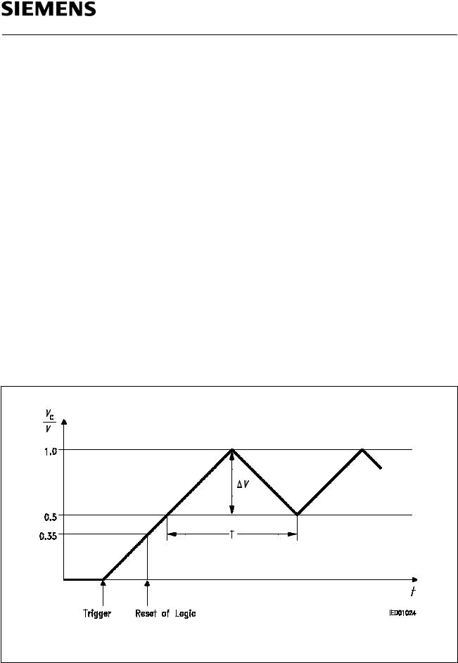
Oscillator
This is a precision triangle oscillator with an external time constant (R x C). Capacitor CC on pin COSC is charged by constant current to 1 V and then discharged to 0.5 V. The constant current is obtained on pin ROSC with an external resistor RR to ground.
When the voltage on COSC is building up, the logic is reset at 350 mV. This always ensures that a complete tone sequence is issued. If the oscillator pin is short-circuited to GND during operation, the sequence is repeated.
The following applies: VC x CC = IC x T/2 with IC = VR/2RR = 1.2 V/2RR |
f0 = 5/8 x 1/(RR x CC) |
Voltages on Pin COSC
Semiconductor Group |
4 |
SAE 800
Logic
The logic unit contains the complete sequence control. The oscillator produces the power-on reset and the clock frequency. Single-tone, dual-tone or triple-tone operation is programmed on inputs E1 and E2. The 4-bit digital/analog converters are driven in parallel. In the event of oscillator disturbance, and after the sequence, the dominant stop output is set. By applying current to pin L, the sequence can be shortened by a factor of 30 for test purposes.
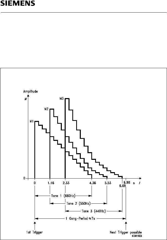
The following figure shows the envelope of the triple-tone sequence:
Envelope of maximum amplitudes of three superimposed tones on Q (time scale for fOSC = 13.2 kHz)
Ratio of maximum amplitudes |
M3 : M2 : M1 = 1 : 0.89 : 0.67 |
Envelope of the Triple-Tone Sequence
Semiconductor Group |
5 |
 Loading...