


S2AS-100 / 200
Solid state single phase meter
User manual
SIEMENS
S2AS-100
S2AS-200
H 71 0200 0015 en

Revision history
Information about document indexes, revision and corrections carried out respectively.
Index |
Date |
Name/phone |
Comments |
- |
17.09.1999 |
D. Opitz - 2892 |
First issue |
© 1999 Siemens Metering Ltd. All rights reserved
Quality and environmental approval
ISO/EN 9001
ISO/EN 14001
Siemens Metering Ltd
H 71 0200 0015 en 1st edition

|
|
|
User manual S2AS-100 / 200 Solid State Single Phase Meter |
|
|
|
Introduction |
Introduction |
|
|
|
Range of validity |
The present user manual applies to the basic version of the meters: |
||
|
• |
S2AS-100 |
(for single phase two wire system with installer switch) |
|
• |
S2AS-200 |
(for single phase two wire system without inst. switch) |
|
Explanations without specific type details apply to both types. |
||
Purpose |
The user manual contains all the information required for application of the |
||
|
meters for the intended purpose. This includes: |
||
|
• Provision of knowledge concerning characteristics, construction and |
||
|
|
function of the meters |
|
|
• Information about possible dangers, their consequences and measures |
||
|
|
to prevent any danger |
|
|
• Details concerning the performance of all work throughout the service |
||
|
|
life of the meters (parametrizing, installation, commissioning, operation, |
|
|
|
maintenance, shutting down and disposal) |
|
Target group |
The contents of this user manual are intended for technically qualified per- |
||
|
sonnel of energy supply companies responsible for the system planning, |
||
|
installation and commissioning, operation, maintenance, decommissioning |
||
|
and disposal of the meters. |
||
Conditions |
The user of this manual has received instruction in basic electrical princi- |
||
|
ples, in particular the various principal types of circuit for energy measure- |
||
|
ment. |
|
|
Subdivision |
This user manual is divided in a logical manner suitable for learning and |
||
|
application, i.e. the individual chapters follow the sequence of information |
||
|
probably required during the various phases of the service life of the me- |
||
|
ters. This provides the following structure: |
||
|
• |
Chapter 1 |
Description of unit |
|
• |
Chapter 2 |
Safety |
|
• |
Chapter 3 |
Construction and Function |
|
• |
Chapter 4 |
Control elements and displays |
|
• |
Chapter 5 |
Programming / Interrogation Interface |
|
• |
Chapter 6 |
Installation and commissioning |
|
• |
Chapter 7 |
Data readout |
|
• |
Chapter 8 |
Metering testing |
|
• |
Chapter 9 |
Detection of faults |
|
• |
Chapter 10 |
Decommissioning, disposal |
Siemens Metering AG |
0-3 |
H 71 0200 0015 en 1st edition

User manual S2AS-100 / 200 Solid State Single Phase Meter
Table of contents
Table of contents |
|
|
1 |
Description of unit........................................................................ |
1 |
1.1 |
Review............................................................................................ |
1 |
1.1.1 |
General Review.............................................................................. |
1 |
1.1.2 |
Type designation ............................................................................ |
2 |
1.2 |
Technical Data ............................................................................... |
3 |
1.2.1 |
Voltage Values ............................................................................... |
3 |
1.2.2 |
Current Values ............................................................................... |
3 |
1.2.3 |
Frequency values ........................................................................... |
4 |
1.2.4 |
Power Consumption ....................................................................... |
4 |
1.2.5 |
Measuring accuracy ....................................................................... |
4 |
1.2.6 |
External influences ......................................................................... |
5 |
1.2.8 |
Output Values................................................................................. |
6 |
1.2.9 |
OptoInterface according IEC 1107............................................... |
7 |
1.2.10 |
Dimensions..................................................................................... |
7 |
1.2.11 |
Connections ................................................................................... |
8 |
2 |
Safety............................................................................................. |
1 |
2.1 |
Safety information .......................................................................... |
1 |
2.2 |
Responsibilities .............................................................................. |
1 |
2.3 |
Safety regulations........................................................................... |
2 |
3 |
Construction and Function ......................................................... |
1 |
3.1 |
Metering Principle........................................................................... |
1 |
3.2 |
Reset and Initialisation ................................................................... |
2 |
3.2.1 |
Normal Reset ................................................................................. |
2 |
3.3 |
Power Down Operation .................................................................. |
2 |
3.4 |
Memory Access.............................................................................. |
3 |
3.5 |
Metering ......................................................................................... |
3 |
3.5.1 |
Register Model ............................................................................... |
3 |
3.5.2 |
Auxiliary input terminal ................................................................... |
4 |
3.5.3 |
Total Register ................................................................................. |
4 |
3.5.4 |
Active Rate selection...................................................................... |
4 |
3.6 |
Configuration File ........................................................................... |
4 |
4 |
Control elements and displays ................................................... |
1 |
4.1 |
LCD Display ................................................................................... |
1 |
4.1.1 |
Display specification....................................................................... |
1 |
4.1.2 |
Normal Displays ............................................................................. |
1 |
4.1.3 |
Dial Checks .................................................................................... |
2 |
4.1.4 |
Annunciators .................................................................................. |
2 |
4.2 |
Switch Control ................................................................................ |
2 |
4.2.1 |
SAS-100 ......................................................................................... |
2 |
4.2.2 |
S2AS-200 ....................................................................................... |
3 |
4.3.1 |
Tariff ID........................................................................................... |
3 |
4.3.2 |
Meter Serial Number ...................................................................... |
3 |
0-4 |
Siemens Metering AG |
H 71 0200 0015 en 1st edition

|
User manual S2AS-100 / 200 Solid State Single Phase Meter |
|
|
|
Introduction |
5 |
Programming / Interrogation Interface |
.......................................1 |
5.1 |
Optical Communication Port ........................................................... |
1 |
6 |
Installation and commissioning.................................................. |
1 |
6.1 |
Introduction..................................................................................... |
1 |
6.2 |
Material and tools required ............................................................. |
1 |
6.3 |
Mounting the meter......................................................................... |
2 |
6.4 |
Connecting meter ........................................................................... |
3 |
6.5 |
Check of connections ..................................................................... |
3 |
6.6 |
Commissioning and functional check ............................................. |
4 |
7 |
Data readout.................................................................................. |
1 |
8 |
Meter Testing ................................................................................ |
1 |
8.1 |
Calibration link ................................................................................ |
1 |
8.2 |
Calibration LED Output................................................................... |
1 |
9 |
Detection of faults ........................................................................ |
1 |
9.1 |
Error Messages .............................................................................. |
1 |
9.2 |
Tamper / Fraud............................................................................... |
1 |
9.3 |
Watchdog and Exception Handling................................................. |
1 |
9.4 |
Reverse Detect ............................................................................... |
1 |
9.5 |
Creep.............................................................................................. |
1 |
9.6 |
Mains Failure .................................................................................. |
2 |
9.7 |
Failure Tolerance............................................................................ |
2 |
9.8 |
Energy Register Locking................................................................. |
2 |
10 |
Decommissioning, disposal ........................................................ |
1 |
Siemens Metering AG |
0-5 |
H 71 0200 0015 en 1st edition
User manual S2AS-100 / 200 Solid State Single Phase Meter
Description of unit
1 Description of unit
1.1Review
1.1.1 General Review
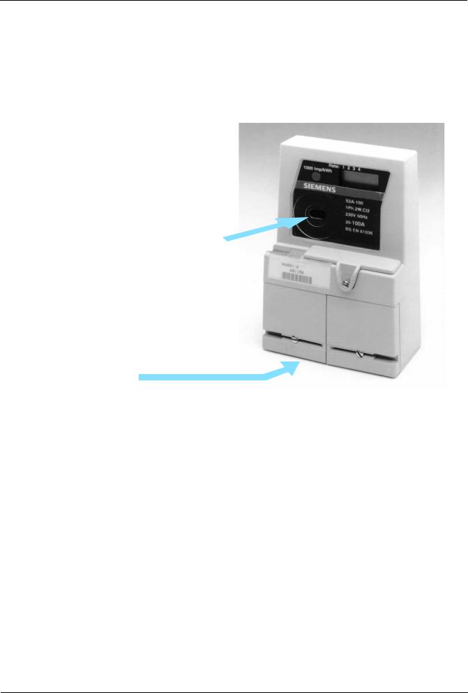
View of meter:
IEC1107
Interface
BS compliant
Terminal
Fig.1 |
General view of meter |
Residential metering
The S2AS meters form a family of solid state single phase meters to cover the whole range of residential metering applications. Single or two rate register, pulse output and communcation interface according IEC 1107. The meters can be used for currents up to 100 A.
The meter is equipped with features to enable the detection of fraud attempts. The meter has a reverse energy register as well as a register recording the number of power-on hours it sees.
A unique feature is the low power consumption which helps to reduce the network losses
Modular design
The meter fulfils the requirements of today’s metering practice, while the design concept is already prepared to cope with tomorrow’s needs in a fully liberalised market. Future requirements can be realised in the form of external circuits incorporated in a module unit that can be adapted to the basic meter (adaptive meter concept).
Siemens Metering AG |
1-1 |
H 71 0200 0015 en 1st edition

User manual S2AS-100 / 200 Solid State Single Phase Meter
Description of unit
Case
The meter is housed in a polycarbonate case designed for the easy fitting of add-on modules. Through its small size and low weight the S2AS meter saves costs in logistics.
1.1.2 Type designation
S2AS-100
Module port
S2AS-200
Module port
Meter with installer switch
The installer switch allows the supply to the premises to be disconnected without drawing the main fuse or disconnecting cables
Meter without installer switch
1-2 |
Siemens Metering AG |
H 71 0200 0015 en 1st edition

User manual S2AS-100 / 200 Solid State Single Phase Meter
Description of unit
1.2Technical Data
1.2.1 Voltage Values
Rated Voltage |
|
|
• |
Nominal as per IEC 61036.................................................... |
230V + 10% |
• |
Range for mains input voltages ................................. |
0.8 up to 1.15 x Un |
Note:
1.The meter is fully operational within 4 seconds of the application of a voltage supply in the above range
2.The meter will power down and inhibit all operations if the mains voltage falls below 150VAC.
3.Between ISO V and 184 V operation is not guaranteed, however the meter will not malfunction, corrupt stored data or register spurious consumption and will power up or down cleanly once the mains input voltage rises above or below these values.
4.The requirements specified in 2 and 4 above, are independent of the rate of change of the mains input voltage.
5.The meter will remain operational for mains voltage interruptions of up to 0.2 seconds. For interruptions of greater than 0.2 seconds, the meter may power down and up again but shall do so without malfunction, corrupting data or registering spurious electricity consumption.
1.2.2 Current Values
Basic current Ib ................................................................ |
either 10A or 20A |
|
|
Maximum Current Imax.................................................. |
either 80A or 100A |
|
|
Maximum measuring range ........... |
up to 120A without exceeding 5% error |
|
|
Creep inhibit circuit operating ............................... |
at approximately 40mA |
Note: Current sensing is by means of a shunt.
Siemens Metering AG |
1-3 |
H 71 0200 0015 en 1st edition
User manual S2AS-100 / 200 Solid State Single Phase Meter
Description of unit
1.2.3 Frequency values
Rated frequency ................................................................................... |
50Hz |
1.2.4 Power Consumption
• |
..............voltage circuit burden |
less than 0.5W and 9VA. Typically 0.4 W |
|
• |
VA burden of the current circuit at Imax .......... |
less than 0.25W / 0.25 VA |
|
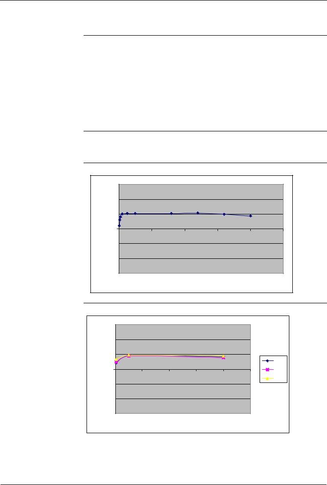
1.2.5 Measuring accuracy
Accuracy
• Accuracy class to IEC 61036 ........................................................ |
class 2 |
Unity Power Factor at 20°C environmental temperature
|
1.5 |
|
|
|
|
|
|
1 |
|
|
|
|
|
|
0.5 |
|
|
|
|
|
Error |
0 |
|
|
|
|
|
% |
0 |
20 |
40 |
60 |
80 |
100 |
|
||||||
|
-0.5 |
|
|
|
|
|
|
-1 |
|
|
|
|
|
|
-1.5 |
|
|
|
|
|
Current (A)
Unity power factor |
|
|
|
|
|
||
|
1.5 |
|
|
|
|
|
|
|
1 |
|
|
|
|
|
|
|
0.5 |
|
|
|
|
|
|
Error |
|
|
|
|
|
|
253v |
0 |
|
|
|
|
|
220v |
|
% |
0 |
20 |
40 |
60 |
80 |
100 |
198v |
|
|||||||
|
-0.5 |
|
|
|
|
|
|
|
-1 |
|
|
|
|
|
|
|
-1.5 |
|
|
|
|
|
|
|
|
|
Current (A) |
|
|
|
|
1-4 |
Siemens Metering AG |
H 71 0200 0015 en 1st edition
User manual S2AS-100 / 200 Solid State Single Phase Meter
Description of unit
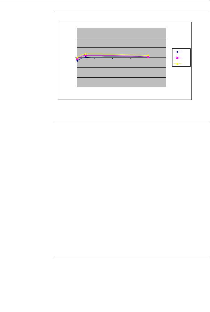
Power Factor = 0.5 Lagging |
|
|
|
|
|||
|
1.5 |
|
|
|
|
|
|
|
1 |
|
|
|
|
|
|
|
0.5 |
|
|
|
|
|
|
Error |
|
|
|
|
|
|
253v |
0 |
|
|
|
|
|
220v |
|
% |
0 |
20 |
40 |
60 |
80 |
100 |
198v |
|
|||||||
|
-0.5 |
|
|
|
|
|
|
|
-1 |
|
|
|
|
|
|
|
-1.5 |
|
|
|
|
|
|
|
|
|
Current (A) |
|
|
|
|
1.2.6 External influences
|
Temperature range |
|
|
|
||
|
• |
Operation ....................................................................... |
|
-10 °C to +45 °C |
||
|
• |
Storage .......................................................................... |
|
-25 °C to +70 °C |
||
|
|
|
|
|
||
|
Temperature Coefficient |
|
|
|||
|
|
|
|
|
|
|
|
|
Current (A) |
|
PF |
Mean Temp Coefficient |
|
|
|
|
|
|
%/K |
|
|
|
1 |
|
1 |
-0.009 |
|
|
|
2 |
|
0.5 |
-0.016 |
|
|
|
10 |
|
1 |
-0.015 |
|
|
|
10 |
|
0.5 |
-0.0019 |
|
|
|
80 |
|
1 |
-0.016 |
|
|
|
80 |
|
0.5 |
-0.005 |
|
|
|
|
|
|||
|
Insulation requirements class 2.......................................................... |
|
4kV* |
|||
(*withstand capability between the voltage and current terminals, including the auxiliary terminals and all metal/conductive parts which the consumer can touch)
Climatic / Type Approval................... |
according to IEC 61036 and OFFER* |
*(UK Office of the Electricty Regulator) additional requirements for type approval of certified meters and indoor meters
Siemens Metering AG |
1-5 |
H 71 0200 0015 en 1st edition
 Loading...