


RWF40...
Compact Universal Controller
optimized for temperature and pressure control through the control of modulating or multi-stage burners
User Manual
The RWF40... controller and this User Manual are intended for use by OEMs which integrate the controller into their products!
CC1B7865E
February 10, 2000
Siemens Building Technologies
Landis & Staefa Division

2/56 |
CC1B7865E |
February 10, 2000 |
Landis & Staefa Division |

Contents |
|
|
1. |
Introduction .......................................................................................... |
6 |
1.1 |
General notes ................................................................................................................. |
6 |
1.2 |
Description ..................................................................................................................... |
6 |
1.3 |
Typographical conventions........................................................................................... |
7 |
1.3.1 |
Warning symbols ............................................................................................................. |
7 |
1.3.2 |
Notification symbols ......................................................................................................... |
7 |
1.3.3 |
Presentation..................................................................................................................... |
7 |
2. |
Type of unit........................................................................................... |
8 |
2.1 |
Type field ........................................................................................................................ |
8 |
3. |
Installation ............................................................................................ |
9 |
3.1 |
Installation site and climatic conditions ...................................................................... |
9 |
3.2 |
Dimensions..................................................................................................................... |
9 |
3.3 |
Side-by-side mounting................................................................................................. |
10 |
3.4 |
Mounting in a panel cutout.......................................................................................... |
10 |
3.5 |
Cleaning the front panel .............................................................................................. |
11 |
3.6 |
Removing the controller module ................................................................................ |
11 |
4. |
Electrical connections ....................................................................... |
12 |
4.1 |
Installation notes.......................................................................................................... |
12 |
4.2 |
Block diagram .............................................................................................................. |
13 |
4.3 |
Assignment of terminals ............................................................................................. |
14 |
4.4 |
Galvanic separation ..................................................................................................... |
17 |
5. |
Operating modes................................................................................ |
18 |
5.1 |
Low-fire operation........................................................................................................ |
18 |
5.2 |
High-fire operation ....................................................................................................... |
18 |
5.2.1 |
Modulating burner, 3-position output.............................................................................. |
18 |
5.2.2 |
Modulating burner, modulating output............................................................................ |
19 |
5.2.3 |
Two-stage burner, 3-position output .............................................................................. |
19 |
5.2.4 |
Two-stage burner, modulating output ............................................................................ |
20 |
5.3 |
Safety shutdown .......................................................................................................... |
20 |
5.4 |
Pre-defined setpoint .................................................................................................... |
20 |
5.4.1 |
Setpoint changeover «SP1 / SP2», analog setpoint shift .............................................. |
21 |
5.4.2 |
Setpoint changeover «SP1» / external setpoint............................................................. |
22 |
5.4.3 |
Setpoint «SP1», analog / binary setpoint shift ............................................................... |
23 |
5.4.4 |
External setpoint, binary setpoint shift ........................................................................... |
24 |
5.5 |
Weather-dependent setpoint shift .............................................................................. |
25 |
5.5.1 |
Heating curve slope ....................................................................................................... |
26 |
5.6 |
Response threshold «Q»............................................................................................. |
27 |
5.7 |
Cold start of the plant .................................................................................................. |
28 |
Landis & Staefa Division |
CC1B7865E |
February 10, 2000 |
3/56 |

6. |
Operation ............................................................................................ |
29 |
|
6.1 |
Basic display................................................................................................................ |
30 |
|
6.1.1 |
Meaning of the display and buttons............................................................................... |
30 |
|
6.2 |
User level...................................................................................................................... |
31 |
|
6.2.1 |
Changing the setpoints.................................................................................................. |
31 |
|
6.2.2 |
Manual operation of a modulating burner...................................................................... |
33 |
|
6.2.3 |
Manual operation of a two-stage burner........................................................................ |
33 |
|
6.2.4 |
Start self-setting ............................................................................................................ |
34 |
|
6.2.5 |
Display of the software version and unit of actual value ............................................... |
34 |
|
6.3 |
Parameter level ............................................................................................................ |
35 |
|
6.3.1 |
Enter parameters........................................................................................................... |
35 |
|
6.4 |
Configuration level ...................................................................................................... |
35 |
|
6.4.1 |
Changing the configuration code................................................................................... |
35 |
|
7. |
Parameter settings ............................................................................. |
36 |
|
8. |
Configuration...................................................................................... |
38 |
|
8.1 |
C111 |
inputs............................................................................................................ |
38 |
8.2 |
C112 |
limit comparator, controller type, setpoint «SP1», locking ..................... |
40 |
8.3 |
C113 |
unit address, dimensional unit, out-of-range............................................ |
44 |
8.3.1 |
SCL |
scaling of standard signal range start, analog input 1................................... |
45 |
8.3.2 |
SCH |
scaling of standard signal range end, analog input 1.................................... |
45 |
8.3.3 |
SCL2 |
scaling of standard signal range start, analog input 2................................... |
45 |
8.3.4 |
SCH2 |
scaling of standard signal range end, analog input 2.................................... |
46 |
8.3.5 |
SPL |
lower setpoint limit......................................................................................... |
46 |
8.3.6 |
SPH |
upper setpoint limit ........................................................................................ |
46 |
8.3.7 |
OFF1 |
actual value correction for analog input 1 ..................................................... |
46 |
8.3.8 |
OFF2 |
actual value correction for analog input 2 ..................................................... |
46 |
8.3.9 |
OFF3 |
actual value correction for analog input 3 ..................................................... |
46 |
8.3.10 |
dF1 |
2nd order digital filter for analog input 1 ......................................................... |
46 |
9. |
Self-setting function........................................................................... |
47 |
|
9.1 |
Self-setting function in high-fire operation ............................................................... |
47 |
|
9.2 |
Checking the controller parameters .......................................................................... |
49 |
|
10. |
What to do if........................................................................................ |
50 |
|
10.1 |
...numbers are flashing on the display ...................................................................... |
50 |
|
4/56 |
CC1B7865E |
February 10, 2000 |
Landis & Staefa Division |

11. |
Technical data .................................................................................... |
51 |
11.1 |
Inputs ............................................................................................................................ |
51 |
11.1.1 |
Analog input 1 (actual value) ......................................................................................... |
51 |
11.1.2 |
Analog input 2 (external setpoint, setpoint shift)............................................................ |
51 |
11.1.3 |
Analog input 3 (outside temperature)............................................................................. |
52 |
11.1.4 |
Binary input «D1»........................................................................................................... |
52 |
11.1.5 |
Binary input «D2»........................................................................................................... |
52 |
11.2 |
Outputs ......................................................................................................................... |
52 |
11.2.1 |
Output 1 (release of burner)........................................................................................... |
52 |
11.2.2 |
Output 2, 3 (3-position output) ....................................................................................... |
52 |
11.2.3 |
Output 4 (limit comparator) ............................................................................................ |
52 |
11.2.4 |
Output 5, modulating output (option).............................................................................. |
53 |
11.2.5 |
Transducer supply.......................................................................................................... |
53 |
11.2.6 |
Interface RS-485 (optional)............................................................................................ |
53 |
11.3 |
General ratings............................................................................................................. |
53 |
11.3.1 |
Measured value accuracy .............................................................................................. |
54 |
11.3.2 |
Measured value circuit monitoring ................................................................................. |
54 |
11.3.3 |
Environmental conditions............................................................................................... |
54 |
12. |
Current settings.................................................................................. |
55 |
12.1 |
Process data................................................................................................................. |
55 |
12.2 |
Parameter level............................................................................................................. |
55 |
12.3 |
Configuration level....................................................................................................... |
56 |
Landis & Staefa Division |
CC1B7865E |
February 10, 2000 |
5/56 |

1. Introduction
1.1 General notes
)Please read this User Manual before starting up the controller. Keep the Manual in a place that is accessible to all users at all times. Please help us improve the Manual.
Your suggestions will be welcome.
*All necessary settings and, where required, settings inside the unit are described in this User Manual, for controller software version 126.01.01.
Ö Section 6.2.5 «Display software version and dimensional unit»
|
|
|
|
|
|
|
|
|
|
|
|
|
|
|
|
|
|
|
|
Should any difficulties arise during commissioning, you are asked not to carry out any |
|
|
|
|
|
|
|
|
|
|
|
|
|
|
|
|
|
|
|
|
unauthorized manipulations on the unit. You could endanger your rights under the unit |
|
|
|
|
|
|
|
|
|
|
|
|
|
|
|
|
|
|
|
|
warranty! Please contact us in such a case. |
|
|
|
|
|
|
|
|
|
|
|
|
|
|
|
|
|
|
|
|
When returning modules, assemblies or components to Landis & Staefa, the regulations |
|
|
|
|
|
|
|
|
|
|
|
|
|
|
|
|
|
|
|
|
of DIN EN 100 015 «Protection of electrostatically sensitive devices» must be observed. |
|
|
|
|
|
|
|
|
|
|
|
|
|
|
|
|
|
|
|
|
Use only the appropriate ESD packaging for transport. |
|
|
|
|
|
|
|
|
|
|
|
|
|
|
|
|
|
|
|
|
|
|
|
|
|
|
|
|
|
|
|
|
|
|
|
|
|
|
|
|
|
Please note that we cannot accept any liability for damage caused by ESD. |
|
|
|
|
|
|
|
|
|
|
|
|
|
|
|
|
|
|
|
|
ESD = electrostatic discharge |
|
|
|
|
|
|
|
|
|
|
|
|
|
|
|
|
|||||
1.2 Description |
|
|
|
|
|
|
|
|
|
|
|
|
|
|
|
|||||
Use |
|
|
|
|
|
|
|
|
|
|
|
|
|
|
The RWF40... is used primarily for controlling temperature or pressure in oilor gas-fired |
|||||
|
|
|
|
|
|
|
|
|
|
|
|
|
|
|
|
|
|
|
|
heating plants. It is a compact 3-position controller without position feedback that acts |
|
|
|
|
|
|
|
|
|
|
|
|
|
|
|
|
|
|
|
|
on the burner. An external switch can be used to change it over to a 2-position controller |
|
|
|
|
|
|
|
|
|
|
|
|
|
|
|
|
|
|
|
|
for the control of two-stage burners. The built-in thermostat function switches the burner |
|
|
|
|
|
|
|
|
|
|
|
|
|
|
|
|
|
|
|
|
on and off. An adjustable response threshold is used to switch to a higher burner output |
|
|
|
|
|
|
|
|
|
|
|
|
|
|
|
|
|
|
|
|
(high-fire operation). |
Control |
|
|
|
|
|
|
|
|
|
|
|
|
|
|
A shift controller controls the temperature or pressure. Minimum and maximum limits for |
|||||
|
|
|
|
|
|
|
|
|
|
|
|
|
|
|
|
|
|
|
|
the setpoint can be set. A self-setting function is available as a standard feature. |
|
|
|
|
|
|
|
|
|
|
|
|
|
|
|
|
|
|
|
|
The plug-in controller module measures 96 x 48 x 127.5 mm and is especially suited for |
|
|
|
|
|
|
|
|
|
|
|
|
|
|
|
|
|
|
|
|
mounting in control panels. The controller incorporates two 4-digit 7-segment displays |
|
|
|
|
|
|
|
|
|
|
|
|
|
|
|
|
|
|
|
|
for the actual value (red) and setpoint (green). A limit comparator is also provided and |
|
|
|
|
|
|
|
|
|
|
|
|
|
|
|
|
|
|
|
|
its switching behavior can be set on the configuration level. |
|
|
|
|
|
|
|
|
|
|
|
|
|
|
|
|
|
|
|
|
A selection can be made between eight different limit comparator functions. |
Options |
|
|
|
|
|
|
|
|
|
|
|
|
|
|
An RS-485 interface is used for integration into a data network. Output 5 can be used as |
|||||
|
|
|
|
|
|
|
|
|
|
|
|
|
|
|
|
|
|
|
|
a modulating output for modulating or 2-stage operation. |
|
|
|
|
|
|
|
|
|
|
|
|
|
|
|
|
|
|
|
|
All connections are made via screw terminals at the rear of the unit. |
6/56 |
CC1B7865E |
February 10, 2000 |
Landis & Staefa Division |

1. Introduction
1.3 Typographical conventions
1.3.1 Warning symbols The signs for Danger and Caution are used in this Manual under the following conditions:
Danger This symbol is used where there may be a danger to personnel if the instructions are disregarded or not strictly followed!
*Caution This symbol is used where there may be damage to equipment or data if theinstructions are disregarded or not strictly followed!
Caution This symbol is used if pre-cautions must be taken in handling electrostatically sensitive components.
1.3.2 Notification symbols |
|
|
) |
Note |
This symbol is used to draw your special attention to a remark. |
ÖReference This symbol refers to additional information in other Manuals, chapters or sections.
abc¹. |
Footnote |
Footnotes are comments, referring to specific parts of the text. They consist of two |
||||||
|
|
|
|
|
|
parts: |
||
|
|
|
|
|
|
1) The markings in the text are arranged as continuous superscript numbers |
||
|
|
|
|
|
|
2) The footnote text is placed at the bottom of the page and starts with a number |
||
|
|
|
|
|
|
|
and a period |
|
|
Action |
This symbol indicates that a required action is described. |
||||||
|
|
|
|
|
|
The individual steps are indicated by an asterisk, e.g.: |
||
|
|
|
|
|
|
Press the ▲ button |
||
1.3.3 Presentation |
|
|
|
|||||
|
|
|
|
|
Buttons |
Buttons are shown in a box. Either symbols or text are possible. If a button has multiple |
||
|
|
PGM |
|
|||||
|
|
|
|
assignments, the text shown is always the one that corresponds to the function |
||||
|
|
|
|
|
|
|||
|
|
|
|
|
|
currently used. |
||
|
|
|
|
|
Button |
The representation of buttons combined with a plus sign means that first the |
||
|
EXIT |
|
|
|||||
|
+ ▲ |
combi- |
|
EXIT |
button must be pressed and held down and then the other button. |
|||
|
|
|
|
|
||||
nations
Landis & Staefa Division |
CC1B7865E |
February 10, 2000 |
7/56 |

2. Type of unit
2.1 Type field
Location
Types
Factory setting
Accessories
The type field is glued onto the housing. The type designation consists of operating voltage and type reference of the unit.
Type of unit |
Description |
|
|
RWF40.000A97 |
Basic version with 3-position output |
RWF40.010A97 ¹· |
|
|
|
RWF40.001A97 |
With additional modulating output |
RWF40.011A97 ¹· |
|
|
|
RWF40.002A97 |
With additional modulating output and |
RWF40.012A97 ¹· |
RS-485 interface |
|
|
¹· Packing variants |
|
*The supply voltage connected must match the voltage given on the type field.
The measured value range and the analog inputs are set at the factory.
ÖChapter 8 «Configuration»
Adapter frame ARG40 for plants where the pre-decessor model RWF32... was used, which shall be converted to the RWF40... .
Bracket ARG41 for mounting the RWF40... on 35 mm DIN rails conforming to DIN 46277.
Dummy cover AVA10.200/109 for covering a control panel cutout for the RWF40...
8/56 |
CC1B7865E |
February 10, 2000 |
Landis & Staefa Division |

3. Installation
3.1Installation site and climatic conditions
−The installation site should be as free as possible from vibrations, dust and corrosive media
−The controller should be installed as far away as possible from sources of electromagnetic fields, such as frequency converters or high-voltage ignition transformers
Relative humidity: < 95 % (non-condensing)
Ambient temperature range: -20...+50 °C
Storage temperature range: -40...+70 °C
3.2 Dimensions
48


 K6
K6
PGM EXIT
RWF40
96 |
91,5 |
112
43,5
Panel cutout to DIN 43700
|
45 +0,6 |
127,5 |
92 +0,8 |
15,5 |
7865m01e/0200 |
Landis & Staefa Division |
CC1B7865E |
February 10, 2000 |
9/56 |
3. Installation
3.3 Side-by-side
If several controllers are mounted side-by-side or above one another in a control panel, the minimum spacing must be observed, namely 30.5 mm vertically and 10.5 mm horizontally.
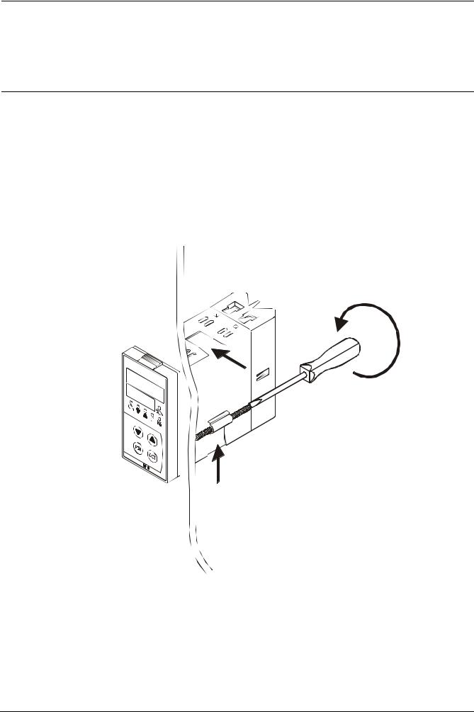
3.4Mounting in a panel cutout
Place the seal provided onto the controller housing.
*The unit must be installed with the seal so that no water or oil can penetrate the housing!
Insert the controller from the front into the panel cutout.
7865z08/0200
At the rear of the panel, push the fixing elements into the guide slots from the side or top. The flat faces of the fixing elements must lie against the housing.
Place the fixing elements against the rear of the panel, and tighten them evenly with a screwdriver.
10/56 |
CC1B7865E |
February 10, 2000 |
Landis & Staefa Division |
3. Installation
3.5. Cleaning the front panel
The front panel can be cleaned with normal washing and rinsing agents or detergents.
*It is not resistant to corrosive acids, caustic solutions and abrasive cleaners, or cleaning with high-pressure cleaners!
3.6Removing the controller module
The controller module can be removed from the housing for servicing.
The rules of DIN EN 100 015 «Protection of electrostatically sensitive devices » must be adhered to for internal work on the controller! No liability will be accepted for damage caused by electrostatic discharge.
7865z09/0200
Press the ribbed surfaces together (at top and bottom) and pull out the controller module.
Landis & Staefa Division |
CC1B7865E |
February 10, 2000 |
11/56 |

4. Electrical connections
4.1 Installation notes
Safety regulations
Fusing
Interference suppression
−The choice of cable, the installation and the electrical connections of the controller must conform to the regulations of VDE 0100 «Regulations for the installation of power circuits with nominal voltages below AC 1000 V», or appropriate local regulations
−The electrical connections may only be carried out by qualified personnel
−If contact with live parts is possible while working on the unit, the controller must be disconnected from the power supply at both poles
−An internal current-limiting resistor interrupts the supply voltage in the event of a shortcircuit. The external fusing should not be rated above 1 A (slow). The output relays must be fused for a maximum of 2 A to prevent contact welding in the event of a shortcircuit in the load circuit
ÖSection 11.2 «Outputs»
−No other loads may be connected to the supply terminals of the controller
−The electromagnetic compatibility and interference suppression levels conform to standards and regulations listed under «Technical data»
ÖChapter 11 «Technical data»
− Input, output and supply cables should be routed separately, not parallel to one another
− Arrange sensor and interface cables as twisted and screened cables, and do not run them close to power cables or components. Ground the screening to the controller at one end to the «TE» terminal
|
− Earth the «TE» terminal of the controller to the protective earth. This cable must have |
|
a cross-sectional area that is at least as large as that of the supply cables. Earthing |
|
cables must be wired in a star configuration to a common earthing point connected to |
|
the protective earth of the supply. Earthing cables may not be looped from one |
|
controller to another |
Incorrect use |
− The unit is not suitable for installation in areas with an explosion hazard |
|
− Incorrect settings on the controller (setpoint, data of parameter and configuration |
|
levels) can affect the proper functioning of the following process or lead to damage. |
|
Safety devices that are independent of the controller, such as overpressure relief |
|
valves or temperature limiters / monitors should therefore always be provided, and |
|
only be capable of adjustment by qualified personnel. Please observe the appropriate |
|
safety regulations. Since self-setting cannot be expected to handle all possible control |
|
loops, the stability of the actual value that is produced should be checked |
|
− The analog inputs of the controller may not exceed a maximum voltage of AC 30 V or |
|
DC 50 V against «TE» |
|
Ö Section 4.3 «Galvanic separation» |
12/56 |
CC1B7865E |
February 10, 2000 |
Landis & Staefa Division |
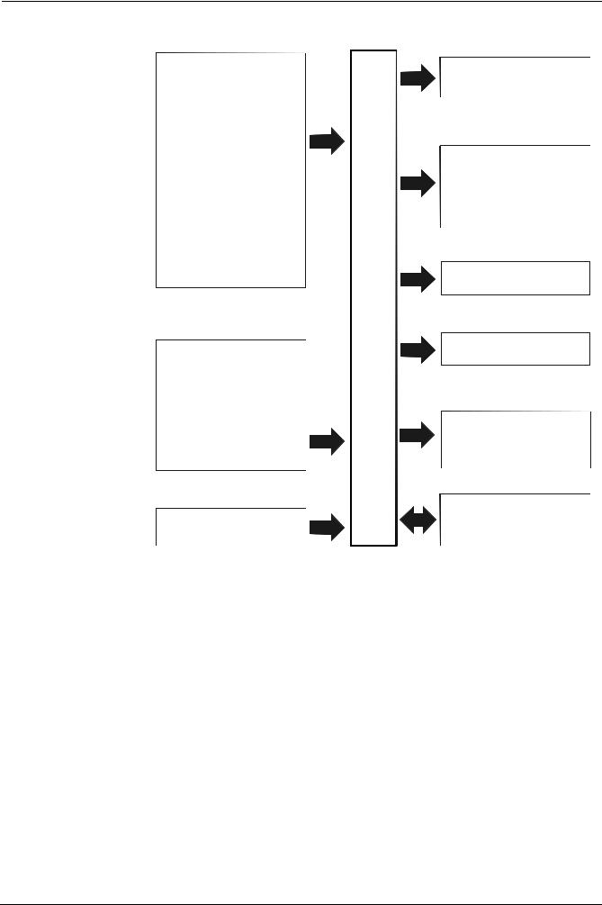
4.2 Block diagram
3 analog inputs
Input 1:
Actual value
for Pt100, Ni100, Pt1000, Ni1000 thermocouples or standard signals
Input 2:
External setpoint, setpoint shift
for resistance 0 - 1 kΩ , or linearised
standard signals
Input 3:
Outside temperature for Pt1000, Ni1000
2 binary inputs
For potential-free contacts
Input 1:
Operating mode changeover
Input 2:
Setpoint shift / changeover
Operating voltage
AC 100 ...240 V,
±10 %, 48...63 Hz
7865f01e/0200
4. Electrical connections
Release of burner
Output 1:
- Relay (N.O. contact)
3-position output
Output 2:
-Relay (reg. unit opens)
Output 3:
- Relay (reg. unit closes)
...RWF40 Limit comparator
Output 4:
- Relay (N.O. contact)
Transducer supply
DC 24 V, 30 mA (short-circuit-proof)
Modulating output (optional)
Output 5:
Modulating output,
DC 0...10 V, DC 0...20 mA,
DC 4...20 mA
Serial interface (optional)
RS-485
MOD bus protocol
Baud rate 9600
Landis & Staefa Division |
CC1B7865E |
February 10, 2000 |
13/56 |

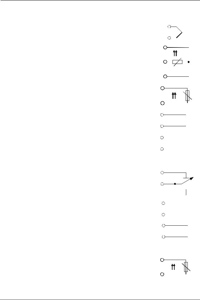
4. Electrical connections
4.3 Assignment of terminals
Electrical connections may only be made by qualified personnel!
X1+ |
CB |
X1- |
CG |
G- |
CA |
G+ |
TE |
GND |
|
D1 |
L1 |
D2 |
N |
I1 |
Y2 |
M1 |
Q |
U1 |
Y1 |
G1+ |
Q13 |
XB6 |
Q14 |
M6 |
|
XU6 |
|
B9 |
Q63 |
M9 |
Q64 |
7865z07/1199
Outputs |
Display LED |
Terminal no. |
Connection diagram |
|||||||||||
Relay 1: release of burner |
|
|
|
Q14 pole |
Q14 |
|
|
|||||||
Contact protection: |
|
|
|
|
|
|
|
|
|
|
|
|
P |
|
|
|
|
|
|
|
|
|
|
|
|
|
|||
Varistor S07K275 |
|
|
|
|
|
|
|
|
|
|
|
|
S |
|
|
|
|
|
|
|
|
|
|
|
|
|
|||
|
|
|
|
|
|
|
|
|
|
|
|
|
||
|
|
|
|
Q13 N.O. contact |
Q13 |
|
|
|||||||
|
|
|
|
|
7865a11/1199 |
|
|
|||||||
|
|
|
|
|
|
|
|
|
||||||
Relay 2: regulating unit opens |
▲ |
Y1 N.O. contact |
Y1 |
|
|
|
S |
|||||||
|
||||||||||||||
Contact protection: |
|
|
|
|
|
|
|
|
|
|
|
|
||
|
|
|
|
|
|
|
|
|
|
|
|
|||
|
|
|
|
|
|
|
|
|
|
|
|
|||
RC unit |
|
|
|
|
|
|
|
|
|
|
|
|
|
|
|
|
|
|
|
|
|
|
|
|
|
|
|
P |
|
|
|
|
|
Q common pole |
Q |
|
|
|
|
|
|
|
|
|
|
|
|
|
|
|
|
|
|
|
|
|
|||
Relay 3: regulating unit closes |
▼ |
|
|
|
|
|
|
|
|
|||||
|
|
|
|
|
|
|
|
|
|
|
||||
Contact protection: |
|
|
|
|
|
|
|
|
|
|
|
|
P |
|
RC unit |
|
|
|
|
|
|
|
|
|
|
|
|
||
|
|
|
|
|
|
|
|
|
|
|
|
|
|
|
|
|
|
|
Y2 N.O. contact |
|
|
|
|
|
|
|
|
S |
|
|
|
|
|
|
|
|
|
|
|
|
|
|||
|
|
|
|
Y2 |
|
|
|
|
|
|
||||
|
|
|
|
|
|
|
|
|
||||||
|
|
|
|
|
|
|
||||||||
|
|
|
|
|
7865a16/1099 |
|
|
|||||||
|
|
|
|
|
|
|
||||||||
Relay 4: limit comparator |
K6 |
Q64 pole |
Q64 |
|
|
|||||||||
Contact protection: |
|
|
|
|
|
|
|
|
|
|
|
|
P |
|
Varistor S07K275 |
|
|
|
|
|
|
|
|
|
|
|
|
|
|
|
|
|
|
|
|
|
|
|
|
|
|
|
S |
|
|
|
|
|
Q63 N.O. contact |
Q63 |
|
|
|||||||
|
|
|
|
|
7865a15/1099 |
|
|
|||||||
|
|
|
|
|
|
|
|
|
||||||
Modulating output (optional) |
|
|
|
X1+ |
X1+ |
|
|
|
|
|
+ |
|||
|
|
|
|
|
||||||||||
DC 0 (4)...20 mA, 0 (2)...10 V |
|
|
|
|
|
|
|
|
|
|
|
|
|
|
|
|
|
|
X1- |
X1- |
|
|
- |
||||||
|
|
|
|
|
|
|||||||||
|
|
|
|
7865a17/1099 |
|
|
||||||||
|
|
|
|
|
|
|
|
|
|
|
|
|
|
|
14/56 |
CC1B7865E |
February 10, 2000 |
Landis & Staefa Division |
4. Electrical connections
Analog input 1 (actual value) |
Terminals |
Connection diagram |
|||||||||||
Thermocouple |
I1 |
I1 |
+ |
|
|
|
|
|
|||||
|
|
|
|
|
|
|
|||||||
|
M1 |
M17865a03/1099 |
- |
|
|
|
|
|
|
||||
|
|
|
|
|
|
|
|
||||||
Resistance thermometer in 3-wire circuit |
M1 |
M1 |
|
|
|
|
|
|
|
|
|||
|
|
|
|
|
|
|
ϑ |
||||||
|
G1+ |
G1+ |
|
|
|
|
|
|
|
|
|
||
|
|
|
|
|
|
|
|
|
|
||||
|
|
|
|
|
|
|
|
|
|
||||
|
|
|
|
|
|
|
|
|
|
||||
|
I1 |
I1 |
|
|
|
|
|
|
|
|
|||
|
7865a04/1099 |
||||||||||||
|
|
||||||||||||
|
|
|
|
|
|
|
|
|
|
|
|
||
Resistance thermometer in 2-wire circuit, line |
M1 |
M1 |
|
|
|
|
|
|
|
|
|||
compensation through offset correction (OFF1) |
|
|
|
|
|
|
ϑ |
|
|
|
|
||
|
|
|
|
|
|
|
|
|
|
|
|||
|
G1+ |
G1+ |
|
|
|
|
|
|
|
|
|
||
|
|
|
|
|
|
|
|
|
|
|
|||
|
|
|
|
|
|
|
|
|
|
||||
|
|
7865a05/1099 |
|
|
|
|
|
|
|
|
|||
|
|
|
|
|
|
|
|
|
|
|
|
|
|
Current input |
I1 |
I1 |
+ |
||||||||||
DC 0...20 mA, 4...20 mA |
|
||||||||||||
|
|
|
|
|
|
|
|
|
|
|
|
|
|
|
M1 |
M1 |
- |
|
|||||||||
|
|
|
|||||||||||
|
|
7865a06/1099 |
|
|
|
|
|
|
|
|
|||
|
|
|
|
|
|
|
|
|
|
|
|
|
|
Voltage input |
U1 |
U1 |
+ |
||||||||||
DC 0...1 V, 0...10 V |
|
||||||||||||
|
|
|
|
|
|
|
|
|
|
|
|
|
|
|
M1 |
M1 |
- |
|
|||||||||
|
|
|
|||||||||||
|
|
7865a07/1099 |
|
|
|
|
|
|
|
|
|||
|
|
|
|
|
|
|
|
|
|
|
|
|
|
|
|
|
|
|
|
|
|||||||
Analog input 2 (setpoint and setpoint shift) |
Terminals |
Connection diagram |
|||||||||||
Resistance potentiometer |
XB6 start |
XB6 |
|
|
A |
||||||||
Offset correction (OFF2) |
|
|
|
|
|
|
|
||||||
|
|
|
|
|
|
S |
|||||||
|
M6 slider |
M6 |
|
||||||||||
|
|
|
|
|
|
|
|
|
|||||
|
|
|
|
|
|
|
|
|
|
||||
|
M6 end |
|
|
|
|
|
|
E |
|||||
|
|
|
|
|
7865a08/1099 |
||||||||
|
|
|
|
|
|
||||||||
|
|
|
|
|
|
|
|
||||||
Current input |
XB6 |
XB6 |
+ |
||||||||||
DC 0..20 mA, 4...20 mA |
|
|
|
|
|
|
|
|
|
|
|
|
|
|
M6 |
M6 |
- |
||||||||||
|
|
7865a09/1099 |
|
|
|
|
|
|
|
|
|||
|
|
|
|
|
|
|
|
||||||
Voltage input |
XU6 |
XU6 |
+ |
||||||||||
DC 0...1 V, 0...10 V |
|
|
|
|
|
|
|
|
|
|
|
|
|
|
M6 |
M6 |
- |
||||||||||
|
|
7865a10/1099 |
|
|
|
|
|
|
|
|
|||
|
|
|
|
|
|
|
|||||||
Analog input 3 (outside temperature) |
Terminals |
Connection diagram |
|||||||||||
Resistance thermometer in 2-wire circuit, line |
B9 |
B9 |
|
|
|
|
|
|
|
|
|||
compensation through offset correction (OFF3) |
|
|
|
|
|
|
ϑ |
|
|
|
|
|
|
|
|
|
|
|
|
|
|
|
|||||
|
M9 |
M9 |
|
|
|
|
|
|
|
|
|
||
|
|
|
|
|
|
|
|
|
|
|
|
||
|
|
|
|
|
|
|
|
|
|
||||
|
7865a13/1099 |
|
|
|
|
|
|
|
|
||||
|
|
|
|
|
|
|
|
|
|
||||
|
|
|
|
|
|
|
|
|
|
|
|
|
|
Landis & Staefa Division |
CC1B7865E |
February 10, 2000 |
15/56 |
4. Electrical connections
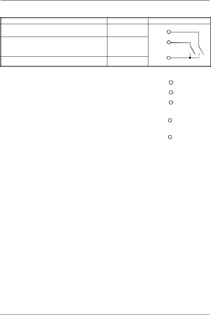
Binary inputs |
Terminals |
Connection diagram |
Operating mode selector |
D1 |
D1 |
Ö Section 5.2 «High-fire operation» |
|
|
Setpoint shift / changeover |
D2 |
D2 |
|
||
Ö Sections 5.4.1...5.4.4 |
|
|
|
GND |
GND |
Common ground |
7865a12/1099 |
Operating voltage, interface |
Terminals |
Connection diagram |
||||
Operating voltage |
L1 line |
L1 |
|
|
|
|
|
|
|
||||
AC 100...240 V ±10 %, 48...63 Hz |
|
N |
|
|
|
|
|
N neutral |
|
|
|
||
|
|
|
|
|||
|
|
TE |
|
|
|
|
Technical earth |
TE |
|
|
|
||
|
|
|
||||
7865a18/1099 |
|
|
||||
|
|
|
|
|
|
|
|
|
|
|
|
||
Operating voltage for transducer |
G+ |
G+ |
|
|
+ |
|
|
||||||
|
|
|
DC 24 V / 30 mA |
|||
|
G- |
G- |
|
- |
|
|
|
|
|
||||
|
|
7865a14/1099 |
|
|
||
|
|
|
|
|
||
Serial interface |
CA |
RxD / TxD+ |
|
|
||
RS-485 |
CB |
RxD / TxD- |
|
|
||
|
CG |
|
|
GND |
|
|
16/56 |
CC1B7865E |
February 10, 2000 |
Landis & Staefa Division |
4. Electrical connections
4.4 Galvanic separation
The diagram shows the maximum potential differences that may exist between the function modules in the controller.
3 analog inputs
Input 1:
Actual value for Pt100, Ni100, Pt1000, Ni1000
thermocouples or standard signals
Input 2:
External setpoint, setpoint shift
for resistance 0...1 k Ω , or standard signals
Input 3:
Outside temperature for Pt1000, Ni1000
2 binary inputs
for potential-free contacts
D1: operating mode changeover
D2: setpoint shift / changeover
Transducer supply
DC 24 V , 30 mA (short-circuit proof)
Modulating output (optional)
Output 5: Modulating output, DC 0...10 V,
DC 0...20 mA, 4...20 mA
Serial interface
RS-485 (optional)
MOD bus protocol baud rate 9600
Limit comparator
Output 4:
- Relay (N.O. contact)
Release of burner L1, N:
Output 1:
- Relay (N.O. contact)
3-position output L1, N:
Output 2:
- Relay (reg. unit opens)
Output 3:
- Relay (reg. unit closes)
Operating voltage L1, N:
AC 100...240 V ±10 %,
48...63 Hz
Max. insulation voltages:
DC 50 V
AC 400 V
AC 4000 V
Technical earth TE
7865f07e/1299
Landis & Staefa Division |
CC1B7865E |
February 10, 2000 |
17/56 |
 Loading...