


 Loading...
s
SC 6002XL Patient Monitor
Field Service Manual
EM Guidelines, 1997-04-02
E331.E551U.719.01.01.02
Replaces/Ersetzt:
ASK-T941-04-7600
ADVISORY
Siemens is liable for the safety of its equipment only if maintenance, repair, and modifications are performed by authorized personnel, and if components affecting the equipment's safety are replaced with Siemens spare parts.
Any modification or repair not done by Siemens personnel must be documented. Such documentation must:
•be signed and dated
•contain the name of the company performing the work
•describe the changes made
•describe any equipment performance changes.
It is the responsibility of the user to contact Siemens to determine warranty status and/or liabilities if other than an authorized Siemens Service Representative repairs or makes modifications to medical devices.
Field Service Manual |
SC 6002XL Patient Monitor |
|
|
Table of Contents
Chapter 1: Introduction . . . . . . . . . . . . . . . . . . . . . . . . . . . . . . . . . . . . . . . . . . . . . . . . . . . 1
1 |
Introduction . . . . . . . . . . . . . . . . . . . . . . . . . . . . . . . . . . . . . . . . . . . . . . . . . . . . . . . . . . . . . . . . . . . . . . . . |
1 |
|
|
1.1 |
Service Strategy . . . . . . . . . . . . . . . . . . . . . . . . . . . . . . . . . . . . . . . . . . . . . . . . . . . . . . . . . . . . . . . . . . |
1 |
|
1.2 |
Replaceable Parts . . . . . . . . . . . . . . . . . . . . . . . . . . . . . . . . . . . . . . . . . . . . . . . . . . . . . . . . . . . . . . . . |
1 |
|
1.3 |
Technical Manual Conventions . . . . . . . . . . . . . . . . . . . . . . . . . . . . . . . . . . . . . . . . . . . . . . . . . . . . . . |
1 |
2 |
Product Overview . . . . . . . . . . . . . . . . . . . . . . . . . . . . . . . . . . . . . . . . . . . . . . . . . . . . . . . . . . . . . . . . . . . |
2 |
|
|
2.1 |
Monitored Patient Parameters . . . . . . . . . . . . . . . . . . . . . . . . . . . . . . . . . . . . . . . . . . . . . . . . . . . . . . . |
2 |
|
2.2 |
SC 6002XL Monitor Controls . . . . . . . . . . . . . . . . . . . . . . . . . . . . . . . . . . . . . . . . . . . . . . . . . . . . . . . . |
2 |
|
2.3 |
TFT-LCD Display . . . . . . . . . . . . . . . . . . . . . . . . . . . . . . . . . . . . . . . . . . . . . . . . . . . . . . . . . . . . . . . . . |
2 |
|
2.4 |
Alarms . . . . . . . . . . . . . . . . . . . . . . . . . . . . . . . . . . . . . . . . . . . . . . . . . . . . . . . . . . . . . . . . . . . . . . . . . |
3 |
|
2.5 |
Monitor/Software Tracking . . . . . . . . . . . . . . . . . . . . . . . . . . . . . . . . . . . . . . . . . . . . . . . . . . . . . . . . . |
3 |
3 |
Preventative Maintenance . . . . . . . . . . . . . . . . . . . . . . . . . . . . . . . . . . . . . . . . . . . . . . . . . . . . . . . . . . . . . |
3 |
|
|
3.1 |
General . . . . . . . . . . . . . . . . . . . . . . . . . . . . . . . . . . . . . . . . . . . . . . . . . . . . . . . . . . . . . . . . . . . . . . . . |
3 |
|
3.2 |
Battery . . . . . . . . . . . . . . . . . . . . . . . . . . . . . . . . . . . . . . . . . . . . . . . . . . . . . . . . . . . . . . . . . . . . . . . . . |
3 |
4 |
Technical Data . . . . . . . . . . . . . . . . . . . . . . . . . . . . . . . . . . . . . . . . . . . . . . . . . . . . . . . . . . . . . . . . . . . . . . |
4 |
|
|
4.1 |
General . . . . . . . . . . . . . . . . . . . . . . . . . . . . . . . . . . . . . . . . . . . . . . . . . . . . . . . . . . . . . . . . . . . . . . . . |
4 |
|
|
Table 1-1 General Specifications . . . . . . . . . . . . . . . . . . . . . . . . . . . . . . . . . . . . . . . . . . . . . . . . . . . . |
4 |
|
4.2 |
Environmental . . . . . . . . . . . . . . . . . . . . . . . . . . . . . . . . . . . . . . . . . . . . . . . . . . . . . . . . . . . . . . . . . . . |
4 |
|
|
Table 1-2 Environmental Specifications . . . . . . . . . . . . . . . . . . . . . . . . . . . . . . . . . . . . . . . . . . . . . . |
4 |
|
4.3 |
Display . . . . . . . . . . . . . . . . . . . . . . . . . . . . . . . . . . . . . . . . . . . . . . . . . . . . . . . . . . . . . . . . . . . . . . . . . |
5 |
|
|
Table 1-3 Display Specifications . . . . . . . . . . . . . . . . . . . . . . . . . . . . . . . . . . . . . . . . . . . . . . . . . . . . |
5 |
|
4.4 |
Outputs . . . . . . . . . . . . . . . . . . . . . . . . . . . . . . . . . . . . . . . . . . . . . . . . . . . . . . . . . . . . . . . . . . . . . . . . |
5 |
|
|
Table 1-4 Output Specifications . . . . . . . . . . . . . . . . . . . . . . . . . . . . . . . . . . . . . . . . . . . . . . . . . . . . |
5 |
|
4.5 |
Connectors . . . . . . . . . . . . . . . . . . . . . . . . . . . . . . . . . . . . . . . . . . . . . . . . . . . . . . . . . . . . . . . . . . . . . |
6 |
|
|
Table 1-5 Connector Specifications . . . . . . . . . . . . . . . . . . . . . . . . . . . . . . . . . . . . . . . . . . . . . . . . . . |
6 |
5 |
Monitor Controls . . . . . . . . . . . . . . . . . . . . . . . . . . . . . . . . . . . . . . . . . . . . . . . . . . . . . . . . . . . . . . . . . . . . |
6 |
|
|
5.1 |
Main Screen Key . . . . . . . . . . . . . . . . . . . . . . . . . . . . . . . . . . . . . . . . . . . . . . . . . . . . . . . . . . . . . . . . . |
6 |
|
5.2 |
Menu Key . . . . . . . . . . . . . . . . . . . . . . . . . . . . . . . . . . . . . . . . . . . . . . . . . . . . . . . . . . . . . . . . . . . . . . |
6 |
|
5.3 |
Alarm Limits Key . . . . . . . . . . . . . . . . . . . . . . . . . . . . . . . . . . . . . . . . . . . . . . . . . . . . . . . . . . . . . . . . . |
7 |
|
5.4 |
Alarm Silence Key . . . . . . . . . . . . . . . . . . . . . . . . . . . . . . . . . . . . . . . . . . . . . . . . . . . . . . . . . . . . . . . . |
7 |
|
5.5 |
All Alarms Off Key . . . . . . . . . . . . . . . . . . . . . . . . . . . . . . . . . . . . . . . . . . . . . . . . . . . . . . . . . . . . . . . . |
7 |
|
5.6 |
NBP Start/Stop Key . . . . . . . . . . . . . . . . . . . . . . . . . . . . . . . . . . . . . . . . . . . . . . . . . . . . . . . . . . . . . . . |
7 |
|
5.7 |
Zoom Key . . . . . . . . . . . . . . . . . . . . . . . . . . . . . . . . . . . . . . . . . . . . . . . . . . . . . . . . . . . . . . . . . . . . . . . |
7 |
|
5.8 |
Record Key . . . . . . . . . . . . . . . . . . . . . . . . . . . . . . . . . . . . . . . . . . . . . . . . . . . . . . . . . . . . . . . . . . . . . |
7 |
ASK-T941-04-7600 |
Siemens Medical Systems, EM-PCS Danvers |
i |
6k2XLSMftcvr.cd-rom.fm/06-00/kaupp
Field Service Manual |
SC 6002XL Patient Monitor |
|
|
Chapter 2: Functional Description . . . . . . . . . . . . . . . . . . . . . . . . . . . . . . . . . . . . . . . . . . . 9
1 Overview . . . . . . . . . . . . . . . . . . . . . . . . . . . . . . . . . . . . . . . . . . . . . . . . . . . . . . . . . . . . . . . . . . . . . . . . . . 9
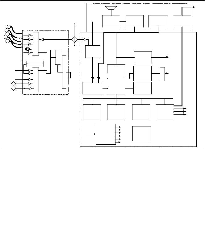
Figure 2-1 SC6002XL Patient Monitor Block Diagram . . . . . . . . . . . . . . . . . . . . . . . . . . . . . . . . . . . . 9
2 Parameter Inputs . . . . . . . . . . . . . . . . . . . . . . . . . . . . . . . . . . . . . . . . . . . . . . . . . . . . . . . . . . . . . . . . . . . . 9
3 Main PC Board . . . . . . . . . . . . . . . . . . . . . . . . . . . . . . . . . . . . . . . . . . . . . . . . . . . . . . . . . . . . . . . . . . . . . . 9
3.1 LCD Control . . . . . . . . . . . . . . . . . . . . . . . . . . . . . . . . . . . . . . . . . . . . . . . . . . . . . . . . . . . . . . . . . . . . 10
3.2 Network Interface . . . . . . . . . . . . . . . . . . . . . . . . . . . . . . . . . . . . . . . . . . . . . . . . . . . . . . . . . . . . . . . 10
3.3 Front Panel Circuitry . . . . . . . . . . . . . . . . . . . . . . . . . . . . . . . . . . . . . . . . . . . . . . . . . . . . . . . . . . . . . 10
3.4 Pod Interface . . . . . . . . . . . . . . . . . . . . . . . . . . . . . . . . . . . . . . . . . . . . . . . . . . . . . . . . . . . . . . . . . . . 10
3.5 Battery Control and ON/OFF Control . . . . . . . . . . . . . . . . . . . . . . . . . . . . . . . . . . . . . . . . . . . . . . . . . 10
3.6 BOOT Process, Flash Memory, and DRAM . . . . . . . . . . . . . . . . . . . . . . . . . . . . . . . . . . . . . . . . . . . 10
3.7 SRAM . . . . . . . . . . . . . . . . . . . . . . . . . . . . . . . . . . . . . . . . . . . . . . . . . . . . . . . . . . . . . . . . . . . . . . . . 10
3.8 68HC11 Microcontroller . . . . . . . . . . . . . . . . . . . . . . . . . . . . . . . . . . . . . . . . . . . . . . . . . . . . . . . . . . . 10
4 Front End . . . . . . . . . . . . . . . . . . . . . . . . . . . . . . . . . . . . . . . . . . . . . . . . . . . . . . . . . . . . . . . . . . . . . . . . . 11
4.1 NIBP Control . . . . . . . . . . . . . . . . . . . . . . . . . . . . . . . . . . . . . . . . . . . . . . . . . . . . . . . . . . . . . . . . . . . 11
4.2 Safety . . . . . . . . . . . . . . . . . . . . . . . . . . . . . . . . . . . . . . . . . . . . . . . . . . . . . . . . . . . . . . . . . . . . . . . . . 11
Figure 2-2 Front End . . . . . . . . . . . . . . . . . . . . . . . . . . . . . . . . . . . . . . . . . . . . . . . . . . . . . . . . . . . . . 12
5 Physiological Parameter Data Acquisition . . . . . . . . . . . . . . . . . . . . . . . . . . . . . . . . . . . . . . . . . . . . . . . . 12
5.1 ECG/Resp . . . . . . . . . . . . . . . . . . . . . . . . . . . . . . . . . . . . . . . . . . . . . . . . . . . . . . . . . . . . . . . . . . . . . 12
Table 2-1 Parameter Sampling Table . . . . . . . . . . . . . . . . . . . . . . . . . . . . . . . . . . . . . . . . . . . . . . . 13
5.1.1 ECG . . . . . . . . . . . . . . . . . . . . . . . . . . . . . . . . . . . . . . . . . . . . . . . . . . . . . . . . . . . . . . . . . . . 13
Figure 2-3 Lead-Forming Network . . . . . . . . . . . . . . . . . . . . . . . . . . . . . . . . . . . . . . . . . . . . . . . . . . 14
5.1.2 Lead Selection . . . . . . . . . . . . . . . . . . . . . . . . . . . . . . . . . . . . . . . . . . . . . . . . . . . . . . . . . . . 14
5.1.3 Lead-Off Detection . . . . . . . . . . . . . . . . . . . . . . . . . . . . . . . . . . . . . . . . . . . . . . . . . . . . . . . 14
5.1.4 Low-Pass Filtering and Common Mode Enhancement . . . . . . . . . . . . . . . . . . . . . . . . . . . . 14
5.2 Respiration . . . . . . . . . . . . . . . . . . . . . . . . . . . . . . . . . . . . . . . . . . . . . . . . . . . . . . . . . . . . . . . . . . . . . 15
Figure 2-4 SpO2 Functional Block Diagram . . . . . . . . . . . . . . . . . . . . . . . . . . . . . . . . . . . . . . . . . . . 15
5.3 SpO2 . . . . . . . . . . . . . . . . . . . . . . . . . . . . . . . . . . . . . . . . . . . . . . . . . . . . . . . . . . . . . . . . . . . . . . . . . 15
5.3.1 SpO2 Front End . . . . . . . . . . . . . . . . . . . . . . . . . . . . . . . . . . . . . . . . . . . . . . . . . . . . . . . . . . 15
Figure 2-5 Sensor LED Timing Diagram . . . . . . . . . . . . . . . . . . . . . . . . . . . . . . . . . . . . . . . . . . . . . . 16
5.3.2 Input Stage . . . . . . . . . . . . . . . . . . . . . . . . . . . . . . . . . . . . . . . . . . . . . . . . . . . . . . . . . . . . . 16
5.3.3 Brightness Control . . . . . . . . . . . . . . . . . . . . . . . . . . . . . . . . . . . . . . . . . . . . . . . . . . . . . . . . 16
5.3.4 Ambient Light Rejection Amplifier . . . . . . . . . . . . . . . . . . . . . . . . . . . . . . . . . . . . . . . . . . . . 16
Figure 2-6 IBP Functional Block Diagram . . . . . . . . . . . . . . . . . . . . . . . . . . . . . . . . . . . . . . . . . . . . . 17
5.4 Invasive Blood Pressure . . . . . . . . . . . . . . . . . . . . . . . . . . . . . . . . . . . . . . . . . . . . . . . . . . . . . . . . . . . 17
5.5 Non-Invasive Blood Pressure . . . . . . . . . . . . . . . . . . . . . . . . . . . . . . . . . . . . . . . . . . . . . . . . . . . . . . . 17
5.5.1 NBP Subsystem . . . . . . . . . . . . . . . . . . . . . . . . . . . . . . . . . . . . . . . . . . . . . . . . . . . . . . . . . 17
Figure 2-7 NBP Functional Block Diagram . . . . . . . . . . . . . . . . . . . . . . . . . . . . . . . . . . . . . . . . . . . . 18
ASK-T941-04-7600 |
Siemens Medical Systems, EM-PCS Danvers |
ii |
6k2XLSMftcvr.cd-rom.fm/06-00/kaupp
Field Service Manual |
SC 6002XL Patient Monitor |
|
|
5.5.2 NBP System Description . . . . . . . . . . . . . . . . . . . . . . . . . . . . . . . . . . . . . . . . . . . . . . . . . . . 18 5.5.3 Operation . . . . . . . . . . . . . . . . . . . . . . . . . . . . . . . . . . . . . . . . . . . . . . . . . . . . . . . . . . . . . . . 18 5.5.4 NBP Hardware . . . . . . . . . . . . . . . . . . . . . . . . . . . . . . . . . . . . . . . . . . . . . . . . . . . . . . . . . . . 19 5.5.5 Valve Control . . . . . . . . . . . . . . . . . . . . . . . . . . . . . . . . . . . . . . . . . . . . . . . . . . . . . . . . . . . . 19 5.5.6 Power Supplies . . . . . . . . . . . . . . . . . . . . . . . . . . . . . . . . . . . . . . . . . . . . . . . . . . . . . . . . . . 19 5.5.7 Power Supply Monitor . . . . . . . . . . . . . . . . . . . . . . . . . . . . . . . . . . . . . . . . . . . . . . . . . . . . . 20 5.5.8 Safety Timer . . . . . . . . . . . . . . . . . . . . . . . . . . . . . . . . . . . . . . . . . . . . . . . . . . . . . . . . . . . . 20 5.5.9 Pressure Channels . . . . . . . . . . . . . . . . . . . . . . . . . . . . . . . . . . . . . . . . . . . . . . . . . . . . . . . . 20
Figure 2-8 Temperature Functional Block Diagram . . . . . . . . . . . . . . . . . . . . . . . . . . . . . . . . . . . . . 20 5.6 Temperature Circuit . . . . . . . . . . . . . . . . . . . . . . . . . . . . . . . . . . . . . . . . . . . . . . . . . . . . . . . . . . . . . . 20 5.6.1 Reference Networks . . . . . . . . . . . . . . . . . . . . . . . . . . . . . . . . . . . . . . . . . . . . . . . . . . . . . . 21 5.6.2 A/D Converter . . . . . . . . . . . . . . . . . . . . . . . . . . . . . . . . . . . . . . . . . . . . . . . . . . . . . . . . . . . 21 Figure 2-9 etCO2 Sensing Process Functional Block Diagram . . . . . . . . . . . . . . . . . . . . . . . . . . . . . 21 6 etCO2 Pod . . . . . . . . . . . . . . . . . . . . . . . . . . . . . . . . . . . . . . . . . . . . . . . . . . . . . . . . . . . . . . . . . . . . . . . . 21 Figure 2-10 Power System Block Diagram . . . . . . . . . . . . . . . . . . . . . . . . . . . . . . . . . . . . . . . . . . . . . 22 6.1 Power Supply System . . . . . . . . . . . . . . . . . . . . . . . . . . . . . . . . . . . . . . . . . . . . . . . . . . . . . . . . . . . . 22 6.1.1 Main Battery . . . . . . . . . . . . . . . . . . . . . . . . . . . . . . . . . . . . . . . . . . . . . . . . . . . . . . . . . . . . 23 6.1.2 AC Power Adapter . . . . . . . . . . . . . . . . . . . . . . . . . . . . . . . . . . . . . . . . . . . . . . . . . . . . . . . . 23
Chapter 3: Subassembly Replacement Procedures . . . . . . . . . . . . . . . . . . . . . . . . . . . |
25 |
|||
1 |
Introduction |
. . . . . . . . . . . . . . . . . . . . . . . . . . . . . . . . . . . . . . . . . . . . . . . . . . . . . . . . . . . . . . . . . . . . . . . |
25 |
|
2 |
Safety Precautions . . . . . . . . . . . . . . . . . . . . . . . . . . . . . . . . . . . . . . . . . . . . . . . . . . . . . . . . . . . . . . . . . . |
25 |
||
3 |
Service Policy and Replaceable Parts . . . . . . . . . . . . . . . . . . . . . . . . . . . . . . . . . . . . . . . . . . . . . . . . . . . |
25 |
||
4 |
Non-Invasive Replacement Procedures . . . . . . . . . . . . . . . . . . . . . . . . . . . . . . . . . . . . . . . . . . . . . . . . . . |
26 |
||
|
4.1 |
Replacing Rotary Knob . . . . . . . . . . . . . . . . . . . . . . . . . . . . . . . . . . . . . . . . . . . . . . . . . . . . . . . . . . . . |
26 |
|
|
4.2 |
Replacing Foot Pads . . . . . . . . . . . . . . . . . . . . . . . . . . . . . . . . . . . . . . . . . . . . . . . . . . . . . . . . . . . . . |
26 |
|
5 |
Accessing Replaceable Subassemblies . . . . . . . . . . . . . . . . . . . . . . . . . . . . . . . . . . . . . . . . . . . . . . . . . . |
26 |
||
|
Figure 3-1 |
Right Side Panel Removal . . . . . . . . . . . . . . . . . . . . . . . . . . . . . . . . . . . . . . . . . . . . . . . . |
26 |
|
|
5.1 |
Removing Side Panels . . . . . . . . . . . . . . . . . . . . . . . . . . . . . . . . . . . . . . . . . . . . . . . . . . . . . . . . . . . . |
26 |
|
|
|
5.1.1 |
Removing Right-Hand Side Panel . . . . . . . . . . . . . . . . . . . . . . . . . . . . . . . . . . . . . . . . . . . . |
27 |
|
Figure 3-2 |
Removing Left Side Panel . . . . . . . . . . . . . . . . . . . . . . . . . . . . . . . . . . . . . . . . . . . . . . . . |
27 |
|
|
|
5.1.2 |
Removing Left Side Panel . . . . . . . . . . . . . . . . . . . . . . . . . . . . . . . . . . . . . . . . . . . . . . . . . . |
27 |
|
|
5.1.3 |
Reinstalling Side Panels . . . . . . . . . . . . . . . . . . . . . . . . . . . . . . . . . . . . . . . . . . . . . . . . . . . . |
28 |
|
Figure 3-3 |
Bezel Retaining Screws . . . . . . . . . . . . . . . . . . . . . . . . . . . . . . . . . . . . . . . . . . . . . . . . . . |
28 |
|
|
5.2 |
Front Bezel Removal . . . . . . . . . . . . . . . . . . . . . . . . . . . . . . . . . . . . . . . . . . . . . . . . . . . . . . . . . . . . . |
28 |
|
|
Figure 3-4 |
Front Bezel Removal . . . . . . . . . . . . . . . . . . . . . . . . . . . . . . . . . . . . . . . . . . . . . . . . . . . . |
28 |
|
|
5.3 |
Replacing Optical Encoder Subassembly . . . . . . . . . . . . . . . . . . . . . . . . . . . . . . . . . . . . . . . . . . . . . |
29 |
|
|
Figure 3-5 |
Optical Encoder Subassembly . . . . . . . . . . . . . . . . . . . . . . . . . . . . . . . . . . . . . . . . . . . . . |
29 |
|
|
|
|
||
ASK-T941-04-7600 |
Siemens Medical Systems, EM-PCS Danvers |
iii |
||
6k2XLSMftcvr.cd-rom.fm/06-00/kaupp
|
Field Service Manual |
|
SC 6002XL Patient Monitor |
|
|
|
|
|
|
5.4 |
Front Bezel Installation . . . . . . . . . . . . . . . . . . . . . . . . . . . . . . . . . . . . . . . . . . . |
. . . . . . . . . . . . . . . . 30 |
||
|
Figure 3-6 |
TFT-LCD Display Subassembly . . . . . . . . . . . . . . . . . . . . . . . . . . . . |
. . . . . . . . . . . . . . . . 30 |
|
5.5 |
Removing/Installing TFT-LCD Subassembly . . . . . . . . . . . . . . . . . . . . . . . . . . . |
. . . . . . . . . . . . . . . . 30 |
||
|
|
5.5.1 |
Removing TFT-LCD Subassembly . . . . . . . . . . . . . . . . . . . . . . . . . . . . |
. . . . . . . . . . . . . . . . 30 |
|
|
5.5.2 |
Installing TFT-LCD Display Subassembly . . . . . . . . . . . . . . . . . . . . . . |
. . . . . . . . . . . . . . . . 31 |
|
Figure 3-7 |
Speaker Subasssembly Connector . . . . . . . . . . . . . . . . . . . . . . . . . |
. . . . . . . . . . . . . . . . 31 |
|
5.6 |
Speaker Replacement. . . . . . . . . . . . . . . . . . . . . . . . . . . . . . . . . . . . . . . . . . . . . |
. . . . . . . . . . . . . . . . 31 |
||
|
Figure 3-8 |
TFT-LCD Display Subassembly (Back View). . . . . . . . . . . . . . . . . . . |
. . . . . . . . . . . . . . . 32 |
|
5.7 |
Front Panel PC Board Replacement . . . . . . . . . . . . . . . . . . . . . . . . . . . . . . . . . |
. . . . . . . . . . . . . . . . 32 |
||
5.8 |
Inverter Board Replacement . . . . . . . . . . . . . . . . . . . . . . . . . . . . . . . . . . . . . . . |
. . . . . . . . . . . . . . . . 32 |
||
|
Figure 3-9 |
Backlight Retaining Tabs Location . . . . . . . . . . . . . . . . . . . . . . . . . . |
. . . . . . . . . . . . . . . . 33 |
|
5.9 |
TFT-LCD Display Backlight Replacement . . . . . . . . . . . . . . . . . . . . . . . . . . . . . |
. . . . . . . . . . . . . . . . 33 |
||
|
5.10PodPort PC Board Removal/Installation . . . . . . . . . . . . . . . . . . . . . . . . . . . . . . . |
. . . . . . . . . . . . . . . . 33 |
||
|
|
5.10.1 Removing PodPort PC Board . . . . . . . . . . . . . . . . . . . . . . . . . . . . . . . . |
. . . . . . . . . . . . . . . . 33 |
|
|
Figure 3-10 Removing PodPort PC Board . . . . . . . . . . . . . . . . . . . . . . . . . . . . . |
. . . . . . . . . . . . . . . . 34 |
||
|
|
5.10.2 Installing PodPort PC Board . . . . . . . . . . . . . . . . . . . . . . . . . . . . . . . . . |
. . . . . . . . . . . . . . . . 34 |
|
|
Figure 3-11 Removing Intermediate Subassembly . . . . . . . . . . . . . . . . . . . . . . . |
. . . . . . . . . . . . . . . . 35 |
||
|
5.11Replacing Intermediate Subassembly . . . . . . . . . . . . . . . . . . . . . . . . . . . . . . . . |
. . . . . . . . . . . . . . . . 35 |
||
|
|
5.11.1 |
Removing Intermediate Subssembly . . . . . . . . . . . . . . . . . . . . . . . . . |
. . . . . . . . . . . . . . . . 35 |
|
|
5.11.2 |
Installing Intermediate Subssembly . . . . . . . . . . . . . . . . . . . . . . . . . . . |
. . . . . . . . . . . . . . . . 35 |
|
5.12Replacing Main Processor Subassembly . . . . . . . . . . . . . . . . . . . . . . . . . . . . . . |
. . . . . . . . . . . . . . . . 36 |
||
|
|
5.12.1 Removing Main Processor Subassembly . . . . . . . . . . . . . . . . . . . . . . |
. . . . . . . . . . . . . . . . 36 |
|
|
Figure 3-12 Securing Screw Access Cover . . . . . . . . . . . . . . . . . . . . . . . . . . . . |
. . . . . . . . . . . . . . . . 36 |
||
|
Figure 3-13 Accessing Main Processor Subassembly . . . . . . . . . . . . . . . . . . . . |
. . . . . . . . . . . . . . . . 36 |
||
|
Figure 3-14 Connector Locations on Main Processor Subassembly . . . . . . . . . |
. . . . . . . . . . . . . . . . 37 |
||
|
|
5.12.2 Installing Main Processor Subassembly . . . . . . . . . . . . . . . . . . . . . . . |
. . . . . . . . . . . . . . . . 37 |
|
|
5.13Monitor Handle . . . . . . . . . . . . . . . . . . . . . . . . . . . . . . . . . . . . . . . . . . . . . . . . . |
. . . . . . . . . . . . . . . . 38 |
||
|
|
5.13.1 |
Removing Handle . . . . . . . . . . . . . . . . . . . . . . . . . . . . . . . . . . . . . . . . |
. . . . . . . . . . . . . . . . 38 |
|
Figure 3-15 Removing Handle retaining Plate . . . . . . . . . . . . . . . . . . . . . . . . . . |
. . . . . . . . . . . . . . . . 39 |
||
|
|
5.13.2 |
Installing Handle . . . . . . . . . . . . . . . . . . . . . . . . . . . . . . . . . . . . . . . . . |
. . . . . . . . . . . . . . . . 39 |
|
Figure 3-16 Location of NBP Subassembly in Rear Housing . . . . . . . . . . . . . . . |
. . . . . . . . . . . . . . . . 40 |
||
|
5.14Replacing NBP Subassembly . . . . . . . . . . . . . . . . . . . . . . . . . . . . . . . . . . . . . . . |
. . . . . . . . . . . . . . . . 40 |
||
|
|
5.14.1 |
Removing NBP Subassembly . . . . . . . . . . . . . . . . . . . . . . . . . . . . . . . |
. . . . . . . . . . . . . . . . 40 |
|
|
5.14.2 |
Installing NBP Subassembly . . . . . . . . . . . . . . . . . . . . . . . . . . . . . . . . |
. . . . . . . . . . . . . . . . 40 |
|
5.15Replacing NBP Air Filters . . . . . . . . . . . . . . . . . . . . . . . . . . . . . . . . . . . . . . . . . . |
. . . . . . . . . . . . . . . . 41 |
||
|
Figure 3-17 NBP Air Intake Filter Access . . . . . . . . . . . . . . . . . . . . . . . . . . . . . . |
. . . . . . . . . . . . . . . . 41 |
||
|
|
5.15.1 Replacing Air Intake Filter . . . . . . . . . . . . . . . . . . . . . . . . . . . . . . . . . . |
. . . . . . . . . . . . . . . . 41 |
|
|
Figure 3-18 NBP Manifold Filter Replacement . . . . . . . . . . . . . . . . . . . . . . . . . . |
. . . . . . . . . . . . . . . . 42 |
||
|
|
|
||
ASK-T941-04-7600 |
Siemens Medical Systems, EM-PCS Danvers |
iv |
||
6k2XLSMftcvr.cd-rom.fm/06-00/kaupp
Field Service Manual |
SC 6002XL Patient Monitor |
|
|
5.15.2 Replacing Manifold Filter . . . . . . . . . . . . . . . . . . . . . . . . . . . . . . . . . . . . . . . . . . . . . . . . . . . 42 5.16Replacing Battery Connector Subassembly . . . . . . . . . . . . . . . . . . . . . . . . . . . . . . . . . . . . . . . . . . . . 42 Figure 3-19 Battery Connector Subassembly . . . . . . . . . . . . . . . . . . . . . . . . . . . . . . . . . . . . . . . . . . . 43 Figure 3-20 Battery Connector Subassembly Access Inside Rear Housing . . . . . . . . . . . . . . . . . . . . 43 5.17Correcting Hardware Revision Number Stored in Monitor . . . . . . . . . . . . . . . . . . . . . . . . . . . . . . . . 44 5.17.1 Windows 3.1 . . . . . . . . . . . . . . . . . . . . . . . . . . . . . . . . . . . . . . . . . . . . . . . . . . . . . . . . . . . . 44 5.17.2 Windows 95 . . . . . . . . . . . . . . . . . . . . . . . . . . . . . . . . . . . . . . . . . . . . . . . . . . . . . . . . . . . . 44 5.17.3 Procedure . . . . . . . . . . . . . . . . . . . . . . . . . . . . . . . . . . . . . . . . . . . . . . . . . . . . . . . . . . . . . . 45 Figure 3-21 Support Menu (Item numbers may differ in different versions of installed software.) . . 45
Chapter 4: Functional Verification and Calibration . . . . . . . . . . . . . . . . . . . . . . . . . . . . 47
1 Functional Verification Tests . . . . . . . . . . . . . . . . . . . . . . . . . . . . . . . . . . . . . . . . . . . . . . . . . . . . . . . . . . 47 1.1 Power Circuits and Startup . . . . . . . . . . . . . . . . . . . . . . . . . . . . . . . . . . . . . . . . . . . . . . . . . . . . . . . . 47 1.2 Optical Encoder . . . . . . . . . . . . . . . . . . . . . . . . . . . . . . . . . . . . . . . . . . . . . . . . . . . . . . . . . . . . . . . . . 47 1.3 TFT-LCD Display . . . . . . . . . . . . . . . . . . . . . . . . . . . . . . . . . . . . . . . . . . . . . . . . . . . . . . . . . . . . . . . . 48 1.4 Fixed Keys . . . . . . . . . . . . . . . . . . . . . . . . . . . . . . . . . . . . . . . . . . . . . . . . . . . . . . . . . . . . . . . . . . . . . 48 1.5 ECG/RESP . . . . . . . . . . . . . . . . . . . . . . . . . . . . . . . . . . . . . . . . . . . . . . . . . . . . . . . . . . . . . . . . . . . . . 49 1.6 Asystole . . . . . . . . . . . . . . . . . . . . . . . . . . . . . . . . . . . . . . . . . . . . . . . . . . . . . . . . . . . . . . . . . . . . . . . 51 1.7 SpO2 . . . . . . . . . . . . . . . . . . . . . . . . . . . . . . . . . . . . . . . . . . . . . . . . . . . . . . . . . . . . . . . . . . . . . . . . . 51 1.8 Temperature . . . . . . . . . . . . . . . . . . . . . . . . . . . . . . . . . . . . . . . . . . . . . . . . . . . . . . . . . . . . . . . . . . . 51
1.8.1 Functional Verification Procedure . . . . . . . . . . . . . . . . . . . . . . . . . . . . . . . . . . . . . . . . . . . . 51 1.8.2 Temperature Calibration Check . . . . . . . . . . . . . . . . . . . . . . . . . . . . . . . . . . . . . . . . . . . . . . 51 Table 4-1 Resistance Value vs. Temperature . . . . . . . . . . . . . . . . . . . . . . . . . . . . . . . . . . . . . . . . . 52 1.9 etCO2 (if installed) . . . . . . . . . . . . . . . . . . . . . . . . . . . . . . . . . . . . . . . . . . . . . . . . . . . . . . . . . . . . . . . 52 Figure 4-1 Test Setup . . . . . . . . . . . . . . . . . . . . . . . . . . . . . . . . . . . . . . . . . . . . . . . . . . . . . . . . . . . . 53
1.10Non-Invasive Blood Pressure . . . . . . . . . . . . . . . . . . . . . . . . . . . . . . . . . . . . . . . . . . . . . . . . . . . . . . . 53 1.10.1 System Setup and Pneumatics Leakage Test . . . . . . . . . . . . . . . . . . . . . . . . . . . . . . . . . . . 53 1.10.2 Functional and Calibration Check . . . . . . . . . . . . . . . . . . . . . . . . . . . . . . . . . . . . . . . . . . . . . 53 Figure 4-2 IBP Test Setup . . . . . . . . . . . . . . . . . . . . . . . . . . . . . . . . . . . . . . . . . . . . . . . . . . . . . . . . 54 1.11Invasive Blood Pressure . . . . . . . . . . . . . . . . . . . . . . . . . . . . . . . . . . . . . . . . . . . . . . . . . . . . . . . . . . . 54 2 Leakage Current Test . . . . . . . . . . . . . . . . . . . . . . . . . . . . . . . . . . . . . . . . . . . . . . . . . . . . . . . . . . . . . . . . 55 Table 4-2 Leakage Current Tests . . . . . . . . . . . . . . . . . . . . . . . . . . . . . . . . . . . . . . . . . . . . . . . . . . 55 Figure 4-3 Block Diagram: Earth Leakage Current (AC/DC Power Adapter) . . . . . . . . . . . . . . . . . . . 56 Figure 4-4 Block Diagram: Earth Leakage Current (CPS/Docking Station) . . . . . . . . . . . . . . . . . . . . 56 Figure 4-5 Block Diagram: Earth Leakage Current (Infinity Docking Station) . . . . . . . . . . . . . . . . . . 56
3 Calibrating NBP System . . . . . . . . . . . . . . . . . . . . . . . . . . . . . . . . . . . . . . . . . . . . . . . . . . . . . . . . . . . . . . 57 3.1 Introduction . . . . . . . . . . . . . . . . . . . . . . . . . . . . . . . . . . . . . . . . . . . . . . . . . . . . . . . . . . . . . . . . . . . . 57 Table 4-3 NBP Calibration Test Equipment . . . . . . . . . . . . . . . . . . . . . . . . . . . . . . . . . . . . . . . . . . . 57
ASK-T941-04-7600 |
Siemens Medical Systems, EM-PCS Danvers |
v |
6k2XLSMftcvr.cd-rom.fm/06-00/kaupp
Field Service Manual |
SC 6002XL Patient Monitor |
|
|
3.2 Calibration Procedure . . . . . . . . . . . . . . . . . . . . . . . . . . . . . . . . . . . . . . . . . . . . . . . . . . . . . . . . . . . . . 58 Figure 4-6 Calibration Potentiometer . . . . . . . . . . . . . . . . . . . . . . . . . . . . . . . . . . . . . . . . . . . . . . . . 59 3.3 Characterization . . . . . . . . . . . . . . . . . . . . . . . . . . . . . . . . . . . . . . . . . . . . . . . . . . . . . . . . . . . . . . . . . 59 Figure 4-7 NBP Characterization Setup . . . . . . . . . . . . . . . . . . . . . . . . . . . . . . . . . . . . . . . . . . . . . . 59 3.3.1 Characterization Setup . . . . . . . . . . . . . . . . . . . . . . . . . . . . . . . . . . . . . . . . . . . . . . . . . . . . . 60 3.3.2 Windows 3.1 . . . . . . . . . . . . . . . . . . . . . . . . . . . . . . . . . . . . . . . . . . . . . . . . . . . . . . . . . . . . 60 3.3.3 Windows 95 . . . . . . . . . . . . . . . . . . . . . . . . . . . . . . . . . . . . . . . . . . . . . . . . . . . . . . . . . . . . 60 3.3.4 Complete Characterization . . . . . . . . . . . . . . . . . . . . . . . . . . . . . . . . . . . . . . . . . . . . . . . . . 60 Figure 4-8 Support Menu (Item numbers may differ between versions of installed software.) . . . . 61
Chapter 5: Troubleshooting . . . . . . . . . . . . . . . . . . . . . . . . . . . . . . . . . . . . . . . . . . . . . . . 63
1 Troubleshooting . . . . . . . . . . . . . . . . . . . . . . . . . . . . . . . . . . . . . . . . . . . . . . . . . . . . . . . . . . . . . . . . . . . . |
63 |
||
1.1 |
Power Problems . . . . . . . . . . . . . . . . . . . . . . . . . . . . . . . . . . . . . . . . . . . . . . . . . . . . . . . . . . . . . . . . |
63 |
|
|
1.1.1 |
No Response When POWER ON/OFF Key Pressed . . . . . . . . . . . . . . . . . . . . . . . . . . . . . . |
63 |
|
Table 5-1 Power-On Problems |
63 |
|
|
1.1.2 |
Power On/Off Piezo Tone Fails to Sound. . . . . . . . . . . . . . . . . . . . . . . . . . . . . . . . . . . . . . . |
65 |
|
Table 5-2 Power-off Alarm Malfunction . . . . . . . . . . . . . . . . . . . . . . . . . . . . . . . . . . . . . . . . . . . . . |
65 |
|
|
1.1.3 |
Power-Up Sequence Fails to Complete Properly . . . . . . . . . . . . . . . . . . . . . . . . . . . . . . . . |
65 |
|
Table 5-3 Power-up Process Malfunction . . . . . . . . . . . . . . . . . . . . . . . . . . . . . . . . . . . . . . . . . . . . |
65 |
|
1.2 |
Optical Encoder Malfunction. . . . . . . . . . . . . . . . . . . . . . . . . . . . . . . . . . . . . . . . . . . . . . . . . . . . . . . 65 |
||
|
Table 5-4 Rotary Knob Malfunction . . . . . . . . . . . . . . . . . . . . . . . . . . . . . . . . . . . . . . . . . . . . . . . . . |
65 |
|
1.3 |
TFT-LCD Display Malfunction.Fixed . . . . . . . . . . . . . . . . . . . . . . . . . . . . . . . . . . . . . . . . . . . . . . . . . . |
65 |
|
|
Table 5-5 LCD Display Malfunction . . . . . . . . . . . . . . . . . . . . . . . . . . . . . . . . . . . . . . . . . . . . . . . . . |
65 |
|
1.4 |
Fixed Key Fails to Function. . . . . . . . . . . . . . . . . . . . . . . . . . . . . . . . . . . . . . . . . . . . . . . . . . . . . . . . . |
66 |
|
|
Table 5-6 Fixed Key Malfunction . . . . . . . . . . . . . . . . . . . . . . . . . . . . . . . . . . . . . . . . . . . . . . . . . . . |
66 |
|
1.5 |
Visual or Audible Alarm Reporting Failure. . . . . . . . . . . . . . . . . . . . . . . . . . . . . . . . . . . . . . . . . . . . . . |
66 |
|
|
Table 5-7 Alarm Malfunctions . . . . . . . . . . . . . . . . . . . . . . . . . . . . . . . . . . . . . . . . . . . . . . . . . . . . . |
66 |
|
1.6 |
NBP Malfunction . . . . . . . . . . . . . . . . . . . . . . . . . . . . . . . . . . . . . . . . . . . . . . . . . . . . . . . . . . . . . . . . |
67 |
|
|
Table 5-8 NBP Malfunctions . . . . . . . . . . . . . . . . . . . . . . . . . . . . . . . . . . . . . . . . . . . . . . . . . . . . . . |
67 |
|
1.7 |
etCO2 Malfunction. . . . . . . . . . . . . . . . . . . . . . . . . . . . . . . . . . . . . . . . . . . . . . . . . . . . . . . . . . . . . . . 67 |
||
|
Table 5-9 etCO2 Malfunctions . . . . . . . . . . . . . . . . . . . . . . . . . . . . . . . . . . . . . . . . . . . . . . . . . . . . |
67 |
|
1.8 |
No Printout from Recorder. . . . . . . . . . . . . . . . . . . . . . . . . . . . . . . . . . . . . . . . . . . . . . . . . . . . . . . . . 68 |
||
|
Table 5-10Recorder Problems . . . . . . . . . . . . . . . . . . . . . . . . . . . . . . . . . . . . . . . . . . . . . . . . . . . . . |
68 |
|
1.9 |
Isolating Cable Malfunctions . . . . . . . . . . . . . . . . . . . . . . . . . . . . . . . . . . . . . . . . . . . . . . . . . . . . . . . |
69 |
|
1.10Patient-Related Data Not Retained or Monitor Fails to Compute Trends . . . . . . . . . . . . . . . . . . . . . |
69 |
||
Appendix A: Replaceable Parts . . . . . . . . . . . . . . . . . . . . . . . . . . . . . . . . . . . . . . . . . . . |
71 |
|
Table A-1 SC 6000XL - Replaceable Parts and Subassemblies . . . . . . . . . . . . . . . . . . . . . . . . . . . . |
72 |
|
Figure A-1 SC 6002XL Exploded View |
73 |
|
|
|
|
ASK-T941-04-7600 |
Siemens Medical Systems, EM-PCS Danvers |
vi |
6k2XLSMftcvr.cd-rom.fm/06-00/kaupp

Field Service Manual |
SC 6002XL Patient Monitor |
Figure A-2 NBP Subassembly (shown with filters exposed) . . . . . . . . . . . . . . |
. . . . . . . . . . . . . . . . 73 |
Appendix B: Connector Pinouts . . . . . . . . . . . . . . . . . . . . . . . . . . . . . . . |
. . . . . . . . . . . . 75 |
Figure B-1 IBP Connector (see Table B-1) . . . . . . . . . . . . . . . . . . . . . . . . . . . . . |
. . . . . . . . . . . . . . . . 75 |
Figure B-2 MultiMed Pod Connector (see Table B-2) . . . . . . . . . . . . . . . . . . . . |
. . . . . . . . . . . . . . . . 75 |
Table B-1 IBP Connector Pinouts . . . . . . . . . . . . . . . . . . . . . . . . . . . . . . . . . . |
. . . . . . . . . . . . . . . . 75 |
Table B-2 MultiMed Pod Connector Pinouts . . . . . . . . . . . . . . . . . . . . . . . . . . |
. . . . . . . . . . . . . . . . 75 |
Figure B-3 Docking Station Connector (see Table B-3) . . . . . . . . . . . . . . . . . . . |
. . . . . . . . . . . . . . . . 76 |
Figure B-4 SHP ACC CBL ALARM UNTERM 5M (see Table B-4) . . . . . . . . . . |
. . . . . . . . . . . . . . . . 76 |
Table B-3 Docking Station Connector Pinouts . . . . . . . . . . . . . . . . . . . . . . . . . |
. . . . . . . . . . . . . . . . 76 |
Table B-4 Remote Alarm Cable Color Code . . . . . . . . . . . . . . . . . . . . . . . . . . |
. . . . . . . . . . . . . . . . 76 |
Figure B-5 Interface Plate Connector (see Table B-5) . . . . . . . . . . . . . . . . . . . . |
. . . . . . . . . . . . . . . . 77 |
Figure B-6 SHP ACC CBL Y RECORDER/ALARM (see Table B-6) . . . . . . . . . . |
. . . . . . . . . . . . . . . . 77 |
Table B-5 Interface Plate Connectors Pinouts . . . . . . . . . . . . . . . . . . . . . . . . . |
. . . . . . . . . . . . . . . 77 |
Table B-6 Remote Alarm Cable Color Code . . . . . . . . . . . . . . . . . . . . . . . . . . . |
. . . . . . . . . . . . . . . . 77 |
Figure B-7 Basic/Device CPS Connectors - Infinity Network (see Table B-7) . . |
. . . . . . . . . . . . . . . . 78 |
Table B-7 InfinityNet CPS Connector Pins . . . . . . . . . . . . . . . . . . . . . . . . . . . . |
. . . . . . . . . . . . . . . . 78 |
Figure B-8 Infinity Docking Station Connectors(Refer to Table B-8.) . . . . . . . . |
. . . . . . . . . . . . . . . . 79 |
Table B-8 Infinity Docking Station Connectors . . . . . . . . . . . . . . . . . . . . . . . . |
. . . . . . . . . . . . . . . . 79 |
Figure B-9 PodPort Connector (see Table B-9) . . . . . . . . . . . . . . . . . . . . . . . . . |
. . . . . . . . . . . . . . . . 80 |
Table B-9 PodPort Connector Pinouts . . . . . . . . . . . . . . . . . . . . . . . . . . . . . . . |
. . . . . . . . . . . . . . . . 80 |
Appendix C: Error and Diagnostic Codes . . . . . . . . . . . . . . . . . . . . . . . . . . . . . . . . . . . 81
1 Introduction . . . . . . . . . . . . . . . . . . . . . . . . . . . . . . . . . . . . . . . . . . . . . . . . . . . . . . . . . . . . . . . . . . . . . . . 81 1.1 Startup Messages . . . . . . . . . . . . . . . . . . . . . . . . . . . . . . . . . . . . . . . . . . . . . . . . . . . . . . . . . . . . . . . 81 1.2 Diagnostic Log . . . . . . . . . . . . . . . . . . . . . . . . . . . . . . . . . . . . . . . . . . . . . . . . . . . . . . . . . . . . . . . . . . 81 Table C-1 Support Menu . . . . . . . . . . . . . . . . . . . . . . . . . . . . . . . . . . . . . . . . . . . . . . . . . . . . . . . . 82 1.3 Severity Codes . . . . . . . . . . . . . . . . . . . . . . . . . . . . . . . . . . . . . . . . . . . . . . . . . . . . . . . . . . . . . . . . . . 82
1.4 Reset Causes . . . . . . . . . . . . . . . . . . . . . . . . . . . . . . . . . . . . . . . . . . . . . . . . . . . . . . . . . . . . . . . . . . . 82 2 Diagnostic Messages . . . . . . . . . . . . . . . . . . . . . . . . . . . . . . . . . . . . . . . . . . . . . . . . . . . . . . . . . . . . . . . . 83 Table C-2 Startup Diagnostic Log Codes . . . . . . . . . . . . . . . . . . . . . . . . . . . . . . . . . . . . . . . . . . . . . 83 Table C-3 Exception Messages . . . . . . . . . . . . . . . . . . . . . . . . . . . . . . . . . . . . . . . . . . . . . . . . . . . . 83 Table C-4 Hardware-related Messages . . . . . . . . . . . . . . . . . . . . . . . . . . . . . . . . . . . . . . . . . . . . . . 84 Table C-5 Intertask Mail Messages . . . . . . . . . . . . . . . . . . . . . . . . . . . . . . . . . . . . . . . . . . . . . . . . . 85 Table C-6 Miscellaneous Messages . . . . . . . . . . . . . . . . . . . . . . . . . . . . . . . . . . . . . . . . . . . . . . . . 85 Table C-7 Alternative Memory Manager to PSOS OSL Messages . . . . . . . . . . . . . . . . . . . . . . . . . 86 Table C-8 NP Subsystem Messages . . . . . . . . . . . . . . . . . . . . . . . . . . . . . . . . . . . . . . . . . . . . . . . . 87 Table C-9 Diagnostic Messages . . . . . . . . . . . . . . . . . . . . . . . . . . . . . . . . . . . . . . . . . . . . . . . . . . . 89 Table C-10INTER Messages . . . . . . . . . . . . . . . . . . . . . . . . . . . . . . . . . . . . . . . . . . . . . . . . . . . . . . 89 Table C-11Print Messages . . . . . . . . . . . . . . . . . . . . . . . . . . . . . . . . . . . . . . . . . . . . . . . . . . . . . . . . 90
ASK-T941-04-7600 |
Siemens Medical Systems, EM-PCS Danvers |
vii |
6k2XLSMftcvr.cd-rom.fm/06-00/kaupp
Field Service Manual |
SC 6002XL Patient Monitor |
|
|
Table C-12MAIN Processor Messages . . . . . . . . . . . . . . . . . . . . . . . . . . . . . . . . . . . . . . . . . . . . . . 91
Table C-13ACT Messages . . . . . . . . . . . . . . . . . . . . . . . . . . . . . . . . . . . . . . . . . . . . . . . . . . . . . . . . 93
Table C-14Audio Messages . . . . . . . . . . . . . . . . . . . . . . . . . . . . . . . . . . . . . . . . . . . . . . . . . . . . . . . 94
Table C-15Database Messages . . . . . . . . . . . . . . . . . . . . . . . . . . . . . . . . . . . . . . . . . . . . . . . . . . . . 95
Table C-16Front End Messages . . . . . . . . . . . . . . . . . . . . . . . . . . . . . . . . . . . . . . . . . . . . . . . . . . . 95
Table C-17Alarm Messages . . . . . . . . . . . . . . . . . . . . . . . . . . . . . . . . . . . . . . . . . . . . . . . . . . . . . . . 97
Table C-18Monitoring Messages . . . . . . . . . . . . . . . . . . . . . . . . . . . . . . . . . . . . . . . . . . . . . . . . . . . 98
Table C-19SpO2 Messages . . . . . . . . . . . . . . . . . . . . . . . . . . . . . . . . . . . . . . . . . . . . . . . . . . . . . . . 98
Table C-20HCOM Messages . . . . . . . . . . . . . . . . . . . . . . . . . . . . . . . . . . . . . . . . . . . . . . . . . . . . . 100
Table C-21LCOM Messages . . . . . . . . . . . . . . . . . . . . . . . . . . . . . . . . . . . . . . . . . . . . . . . . . . . . . 101
Table C-22NET Messages . . . . . . . . . . . . . . . . . . . . . . . . . . . . . . . . . . . . . . . . . . . . . . . . . . . . . . . 103
Table C-23etCO2 Messages . . . . . . . . . . . . . . . . . . . . . . . . . . . . . . . . . . . . . . . . . . . . . . . . . . . . . 103
Appendix D: Functional Verification Checklist . . . . . . . . . . . . . . . . . . . . . . . . . . . . . . |
105 |
Appendix E: Supplemental Documents . . . . . . . . . . . . . . . . . . . . . . . . . . . . . . . . . . . |
107 |
Software Installation Instructions - Software Version VE0 . . . . . . . . . . . . . |
109 |
Service Setup Instructions - Software Version VE0 . . . . . . . . . . . . . . . . . . . |
110 |
ASK-T941-04-7600 |
Siemens Medical Systems, EM-PCS Danvers |
viii |
6k2XLSMftcvr.cd-rom.fm/06-00/kaupp
Chapter 1: Introduction
1 Introduction
1.1 Service Strategy
1.2 Replaceable Parts
1.3Technical Manual Conventions
In keeping with the service strategy for the SC6002XL, this service manual provides the necessary information required to service an SC 6002XL patient monitor in the field. The SC 6002XL is both a stationary and a portable monitor designed to monitor patient vital signs (refer to user’s guide for monitoring options). For stationary operation near a bedside, the monitor is connected to an AC/DC power adapter or placed on a specially designed docking station attached to a shelf, wall, or rolling stand that securely locks it into place. While on the docking station, the monitor is powered by a CPS or an IDS power supply. When the monitor is detached from a CPS or IDS, it is powered by a lead acid battery or by an optional Lithium ion battery. The monitor is reattached to the AC/DC Power Adapter or placed back on a CPS or IDS to recharge the battery.
The monitor has been designed for high reliability, with an estimated MTBF of 50,000 hours (5.7 yrs.) of continuous operation.
Therefore, the service strategy is based on few failures in the field, a clear definition of failure analysis by field service personnel, and a quick repair turnaround. The field repair philosophy is based on the distributed and approved spare parts list. Refer to Appendix A: Replaceable Parts.
This manual is intended to serve as a source of technical information, for qualified field service personnel to use in servicing SC6002XL patient monitor in accordance with the Siemens Service Strategy. Field service is expected to be successful “First-Time Every Time.”
SC 6002XL monitors have several replaceable subassemblies, each of which also has replaceable subassemblies and/or components.
•Front Bezel Subassembly
•Front Panel PC Board
•TFT-LCD Display Subassembly,
•Main Processor Subassembly,
•NBP Subassembly, and
•Rear Housing Subassembly with integrated serial number chip.
Individual “consumable” replaceable parts include the battery, fluorescent backlight, and NBP filters. A complete listing of spare parts is included in Appendix A: Replaceable Parts of this manual. Replacement of components other than those listed in Appendix A should be performed only at Siemens service depots in Danvers, MA, U.S.A. or in Solna, Sweden, where specialized repair and testing equipment can assure product reliability.
The following conventions are employed in this manual:
A NOTE calls attention to items of special interest or provides additional related information about a specific topic:
Note: Attempting to repair any PC board to the component level may void any warranty, either express or implied.
A Caution indicates a potentially hazardous situation which, if not avoided, may result in minor or moderate property damage. It may also alert against unsafe practices.
ASK-T941-04-7600 |
Siemens Medical Systems, EM-PCS Danvers |
1 |
6k2XLSMC1.cd-rom.fm/06-00/kaupp

SC 6002XL Patient Monitor |
Field Service Manual |
|
|
Caution |
3 |
|
Printed circuit boards in these monitors contain components that are easily damaged by static electricity. Open monitors only in a static-protected environment. Observe proper procedures to prevent damage to the equipment resulting from static discharge.
A Warning indicates a potentially hazardous situation which, if not avoided, may result in death or serious injury.
2 Product Overview
Warning
Do not operate this product in the presence of flammable gasses or liquids. If this device is operated where flammable anesthetics, skin cleansers, or disinfectants are used, the possibility of an explosion cannot be excluded. This product must be operated only in strict conformance with local fire prevention regulations.
SC 6002XL Patient Monitors are light-weight, battery-equipped, hand-held or semi-permanently mounted devices for general purpose monitoring of a preconfigured set of physiological parameters. When not connected to a hospital’s main ac power, they use a battery with approximately 1¼ hours (3 hrs. for Li option battery) of operating time. A power adapter, CPS/ docking station combination, or IDS, which also charges the battery, can be used to operate the monitor from the hospital’s main ac power circuit.
2.1Monitored Patient Parameters
The SC6002XL monitors the following physiological parameters:
• ECG (three-lead, five-lead, or six-lead pod)
•Respiration
•Pulse Oximetry (SpO2 and PR)
•Temperature
•NBP
•IBP1, IBP2 (locked option)
•etCO2 via PodComm Port (locked option)
•Arrythmia
•OCRG (locked option)
•Dual Lead S-T Segment Analysis (locked option, ≥ VF0 SW required)
2.2SC 6002XL Monitor All functions are controlled by a 16-position rotary knob and nine front
Controls |
panel fixed keys - Alarm Silence, Record, Alarm Limits, NBP Start/Stop, All |
|
Alarms Off, Zoom, Main Screen, Menu, and ON/OFF. Turning the rotary |
|
knob locates different menu items, and pressing the knob in selects the |
|
item. Depending on the item selected, pressing the knob in may either |
|
bring up another menu or initiate an action. See Section 5. For detailed |
|
operating instructions, consult the SC 6002XL Patient Monitor User Guide |
|
applicable to the installed software. |
2.3 TFT-LCD Display
The SC 6002XL monitor has a 6.5 inch (16.5cm), 3-channel color TFT-LCD display. Waveforms display in Erase Bar mode at 25 ±20% mm/s (except for respiration and etCO2 waveforms which display at 6.25 ±20% mm/s). All displays for a given parameter (label, unit of measure, and waveform) are in the same color. If a waveform is not displayed for a parameter, its label is gray.
2 |
Siemens Medical Systems, EM-PCS, Danvers |
ASK-T941-04-7600 |
6k2XLSMC1.cd-rom.fm/06-00/kaupp
Field Service Manual |
SC 6002XL Patient Monitor |
|
|
|
|
2.4 |
Alarms |
Alarm limits can be set either on a user-definable setup table, or |
|
|
automatically based on current parameter values. Three alarm grades, |
|
|
each with a distinct alarm tone, announce alarm situations of varying |
|
|
severity: |
|
|
• life-threatening (asystole or ventricular fibrillation - red) |
|
|
• serious (parameter limit alarms - yellow) |
|
|
• advisory (technical alarms - white) |
|
|
The message field background and parameter field of the parameter in |
|
|
alarm are displayed in the color associated with the alarm grade as given |
|
|
above. |
2.5 |
Monitor/Software |
Each monitor has a unique ID chip installed in its rear housing for diagnostic |
|
Tracking |
and tracking purposes, and un/locking optional software features. |
3Preventative Maintenance
3.1 |
General |
SC 6002XL monitors require replacement of the lead-acid battery (12 months), |
||
|
|
NBP air intake filter (24 months) and fluorescent bulb (45K - 50K hours). |
|
|
|
|
Siemens recommends that a full functional verification be performed |
|
|
|
|
annually. See Chapter 4: Functional Verification and Calibration. Also, some |
||
|
|
national jurisdictions require that a temperature calibration (see Section |
|
|
|
|
1.8.2 in Chapter 4) and an NBP calibration be performed at least every two |
||
|
|
years. Refer to Section 3, Calibrating NBP System in Chapter 4 for the NBP |
||
|
|
calibration procedure. |
|
|
|
|
|
Note: Replace the internal manifold filter on the NBP subassembly |
|
|
|
|
only if the NBP subassembly should fail characterization. |
|
3.2 |
Battery |
To obtain maximum life from a new lead-acid battery, install the battery |
|
|
|
|
into the monitor and run the monitor on battery power for a period of 15 |
|
|
|
|
minutes. After the 15 minute period, either plug in the monitor’s power |
|
|
|
|
adapter or lock the monitor onto a powered docking station and charge the |
||
|
|
battery, or remove the battery from the monitor and connect the battery to |
||
|
|
an external charger. (This initial sequence is not needed for Li batteries.) |
|
|
|
|
When in storage or not in use for an extended period of time, lead-acid |
|
|
|
|
batteries self-discharge and develop a “float-charge” as a characteristic of |
|
|
|
|
the self-discharge process. The “float charge” must be drained off before |
|
|
|
|
the battery can be properly charged. If a new battery is immediately placed |
||
|
|
on a charger, the “float charge” provides an incorrect indication of the |
|
|
|
|
battery’s charge condition, and the charger may not fully charge the battery. |
||
|
|
Between discharges, the lead-acid battery must be recharged as soon as |
||
|
|
possible. Once charged, it can be stored for ª 4 months without recharging. |
||
|
|
Siemens recommends that the battery charge be maintained at >80% to |
||
|
|
maximize the battery’s capacity and cycle life. Starting at a 100% charge |
||
|
|
level, at room temperature the battery will self-discharge below the |
|
|
|
|
acceptable minimum in about 6 months on a shelf and in about 2 months |
||
|
|
in an unpowered spare monitor. |
|
|
|
|
|
|
|
|
|
|
Warning |
|
|
|
|
Dispose of used batteries in accordance with local regulations |
|
|
|
|
governing disposal of hazardous materials. |
|
|
|
|
|
|
|
|
|
|
|
ASK-T941-04-7600 |
Siemens Medical Systems, EM-PCS Danvers |
3 |
||
6k2XLSMC1.cd-rom.fm/06-00/kaupp
SC 6002XL Patient Monitor |
Field Service Manual |
|
|
4 Technical Data
Technical Data included in this Section is as of publication date of this Manual. Changes are reported in User Guide applicable to installed SW.
4.1 General
Table 1-1 General Specifications
Parameter |
Specification |
|
|
Power Requirements |
100-250 VAC through AC power adapter |
|
|
Mains Frequency |
50/60 Hz |
|
|
AC Power Consumption |
60 VA AC |
|
|
Battery Type |
Lead-acid: PANASONIC LC-T121R8PU or equivalent |
|
Lithium-ion: Siemens Li+ Battery Pack |
|
|
DC Input |
11 - 14 V; 32 W continuous, 49 W peak |
|
|
Battery Operating Time (means |
Lead-acid: 75 mins |
running with NBP measurement |
Lithium-ion: 180 mins |
every 15 min @ 25°C temperature, |
|
no etCO2 running |
|
Battery Recharging Time |
Lead-acid: 5 ½ hours, typical |
|
Lithium-ion: 8 hours, typical |
|
|
Battery Charge/Discharge/Charge: |
Lithium-ion only (operating as defined above): 2 hours, charging for 2 |
|
hours, operating 2 hours |
|
|
Patient Leakage Current |
< 10 µA @ 110 V and 60 Hz (per UL 544) |
|
< 10 µA @ 220 V and 50 Hz (per IEC 601-1) |
|
|
Chassis Leakage Current with |
< 100 µA @ 110 V and 60 Hz (per UL 544) |
battery eliminator |
< 500 µA @ 220 V and 50 Hz (per IEC 601-1) |
|
|
4.2 Environmental
Table 1-2 Environmental Specifications
|
Parameter |
|
Environmental Specification |
|
|
|
|
|
|
|
|
|
Cooling Method |
|
Convection and cooling chimney (no fan) |
|
|
|
|
|
|
|
|
|
Temperature: |
|
|
|
|
|
Operating |
|
0°C to +40°C (without recorder) |
|
|
|
Storage |
|
-20°C to +50°C |
|
|
|
|
|
|
|
|
|
Relative Humidity: |
|
|
|
|
|
Operating |
|
>30% and <95%, non-condensing |
|
|
|
Storage |
|
>10% and <95% non-condensing |
|
|
|
|
|
|
|
|
|
Altitude: |
|
|
|
|
|
Operating |
|
-381 to +3048 m (-1250 to 10,000 ft.) |
|
|
|
|
|
525 to 795 mmHg (70.0 to 106 kPa) |
|
|
|
Storage |
|
-381 to 5486 m (-1250 to 18,000 ft.) |
|
|
|
|
|
375 to 795 mmHg (50.0 to 106 kPa) |
|
|
|
|
|
|
|
|
|
Water Resistance |
|
Drip-Proof |
|
|
|
|
|
|
|
|
|
Dimensions (H x W x D): |
|
196 x 223 x 134 mm (7.7 x 8.8 x 5.3 in) (w/ rotary knob) |
|
|
|
|
|
|
|
|
|
|
|
|
|
|
4 |
Siemens Medical Systems, EM-PCS, Danvers |
ASK-T941-04-7600 |
|
||
6k2XLSMC1.cd-rom.fm/06-00/kaupp
|
|
Field Service Manual |
|
SC 6002XL Patient Monitor |
|
||
|
|
|
|
|
|
||
|
|
Table 1-2 Environmental Specifications (Continued) |
|
|
|||
|
|
|
|
|
|
|
|
|
|
|
Parameter |
|
Environmental Specification |
|
|
|
|
|
|
|
|
|
|
|
|
Weight: |
|
|
|
|
|
|
|
|
SC 6002XL (w/o etCO2) |
|
3.42 kg (7.54 lb) w/ lead-acid battery |
|
|
|
|
|
|
|
3.22 kg (7.10 lb) w/ lithium-ion battery |
|
|
|
|
|
|
|
2.87 kg (6.32 lb)) w/o battery |
|
|
|
|
|
Battery |
|
Lead-acid: 0.55 kg (1.22 lb) |
|
|
|
|
|
|
|
Lithium-ion: 0.35 kg (0.78 lb) |
|
|
|
|
|
|
|
|
|
|
|
|
Finish: |
|
Front: white |
|
|
|
|
|
|
according to Siemens |
|
Rear and Handle: anthracite gray |
|
|
|
|
|
Corporate Design Guidelines |
|
Material: ABS Polycarbonate Blend (injection molded plastic) |
|
|
|
|
|
|
|
|
|
|
4.3 |
Display |
|
|
|
|
||
|
|
Table 1-3 Display Specifications |
|
|
|
|
|
|
|
|
|
|
|
|
|
|
|
|
Parameter |
|
Specification |
|
|
|
|
|
|
|
|
|
|
|
|
Type |
|
Color Thin Film Transistor - Liquid Crystal Display (TFT-LCD) |
|
|
|
|
|
|
|
|
|
|
|
|
|
Size |
|
170 mm (6.7 in) diagonal |
|
|
|
|
|
|
|
|
|
|
|
|
|
Resolution |
|
640 x 480 pixels |
|
|
|
|
|
|
|
|
|
|
|
|
|
Active Viewing Area |
|
132.5 x 99.4 mm |
|
|
|
|
|
|
|
|
|
|
|
|
|
Pixel pitch |
|
0.207 mm x 0.207 mm |
|
|
|
|
|
|
|
|
|
|
|
|
|
Sweep Speeds |
|
fixed 25 mm/s ±20% for ECG, SpO2, and IBP curves |
|
|
|
|
|
|
|
|
fixed 6.25 mm/s ±20% for Rsp and etCO2 curves |
|
|
|
|
Display Mode |
|
Erase bar (updates waveforms from left to right) |
|
|
|
|
|
|
|
|
|
|
|
4.4 |
Outputs |
|
|
|
|
||
|
|
Table 1-4 Output Specifications |
|
|
|
|
|
|
|
|
|
|
|
|
|
|
|
|
Parameter |
|
Specification |
|
|
|
|
|
|
|
|
|
|
|
|
QRS Synchronization: |
|
|
|
|
|
|
|
|
Timing: |
|
For heart rates from 30 to 250 [1/min], with QRS widths from 40 to 120 |
|
|
|
|
|
|
|
msec and QRS amplitudes from 0.5 to 5 mV, a sync pulse is delayed no |
|
|
|
|
|
|
|
more than 35 msec from peak of R-wave for each valid QRS complex. |
|
|
|
|
|
Output Pulse: |
|
+12 V, 100 ms duration |
|
|
|
|
|
|
|
|
|
|
|
|
Alarm Output |
|
12 V Open collector output for external alarm indicator |
|
|
|
|
|
|
|
|
|
|
|
|
|
Recorder |
|
UART interface w/ recorder through interface plate or docking station |
|
|
|
|
|
|
|
|
connector |
|
|
|
|
|
|
|
|
|
|
|
|
Debug Port |
|
UART interface w/ a PC to retrieve diagnostic information through |
|
|
|
|
|
|
|
|
interface plate or docking station connector |
|
|
|
|
|
|
|
|
|
|
|
|
External VGA |
|
Video signals sent to external VGA display for remote viewing of |
|
|
|
|
|
|
|
|
SC6002XL screen. -- not available when Infinity Serial Hub interface plate |
|
|
|
|
|
|
|
in use. |
|
|
|
|
|
|
|
|
|
|
|
|
Export Protocol |
|
UART interface w/ external devices using proprietary export protocol. -- |
|
|
|
|
|
|
|
|
not available when Infinity Serial Hub interface plate in use. |
|
|
|
|
|
|
|
|
|
|
|
|
Network |
|
Serial connection to Infinity Network through Infinity Serial Hub interface |
|
|
|
|
|
|
|
|
plate or docking station connector. |
|
|
|
|
|
|
|
|
||
|
|
|
|
|
|
|
|
ASK-T941-04-7600 |
Siemens Medical Systems, EM-PCS Danvers |
5 |
|
||||
6k2XLSMC1.cd-rom.fm/06-00/kaupp

SC 6002XL Patient Monitor Field Service Manual
4.5 Connectors
Table 1-5 Connector Specifications
Parameter |
Specification |
|
|
DC Input |
Siemens 2-pin power connector |
|
|
Docking Station |
Siemens 28-pin connector to provide Alarm Output, Recorder, Debug |
|
Port, Network, External VGA and Power |
|
|
Memory Card |
PCMCIA slot |
|
|
QRS Sync |
Phone jack connector |
|
|
MultiMed Pod |
16-pin shielded female input connector |
|
|
IBP |
7-pin shielded female input connector |
|
|
NBP Hose |
One-hand coupling system |
|
|
etCO2 |
7-pin shielded female PodComm connector |
Note: For patient parameter specifications, refer to User Guide applicable to installed software version.
5 Monitor Controls
5.1Main Screen Key
5.2Menu Key
The rotary knob in the lower right corner of the front panel is a pointing and selecting device. Turn the knob to select a screen area or menu item or to change a default value, and press the knob in to confirm your selection and to set a default value. Press Main Screen key to return to the MAIN screen.
Note: Instructions in this chapter are intended to provide only a cursory overview of basic monitor controls for accessing and performing service-related functions. Refer to the User Guide for the installed software version for complete operating information.
Pressing the Main Screen key exits the current menu or screen and displays the home screen.
--provides access to the Main menu. In general, functions of direct concern to the CSE or Biomed are accessed via Monitor Setup → Biomed on the Main menu. Password-protected service-related functions are to be performed by only authorized technical personnel. Use Biomed password (375) to access the following:
•Save Setups - Confirm or Cancel
•Locked Options - four locks into which monitor-specific 2-digit codes must be entered to enable locked options
•Diagnostic Logs
•Units
-Temperature - °C or °F
-Pressure - mmHg or kPa
•Service - requires Service password. (The password is given on the Service Setup Instructions for the installed software version.)
-Update Software
-Line Frquency - set the frequency equal to the ac mains line according to local conditions (50 or 60 Hz).
Note: An incorrect setting of line frequency can cause artifact or excessive waveform noise on the ECG waveform.
-Language - selection appropriate for clinical site
6 |
Siemens Medical Systems, EM-PCS, Danvers |
ASK-T941-04-7600 |
6k2XLSMC1.cd-rom.fm/06-00/kaupp
Field Service Manual |
SC 6002XL Patient Monitor |
|
|
5.3Alarm Limits Key
5.4Alarm Silence Key
5.5All Alarms Off Key
5.6NBP Start/Stop Key
5.7Zoom Key
5.8Record Key
-Test Pulse - Confirm or Cancel, one-shot test pulses for ECG (1mV spike) and Temp (–5°C and +50°C, respectively). An
additional test is performed for IBP, Resp Pulse, and SpO2. Test indication is reported in the trend table.)
•Exit
--calls up a setup table for alarms.
1)Turn rotary knob to select desired parameter field and limits, and press knob in to activate your selection.
2)The number representing the limit value turns black on a blue background, indicating that you can change it. Turn knob to change value.
3)When desired setting is displayed, press knob in to set value.
4)Press MAIN Screen key to return to MAIN screen.
--silences an active alarm tone for 1 minute ±5 seconds, and turns active blinking parameter areas into active steady parameter areas
--suspends alarms for a fixed 3-minute ±5 second period.
--starts and stops non-invasive blood pressure measurement.
--used for fast access to all parameters or NBP parameter box bottom channel screen setups, choice made from a user menu.
With an R50™ recorder connected, press the Record fixed key to start a manual, timed recording.
Note: If a recorder is not connected, pressing the Record fixed key writes 15 seconds of waveform and vital signs information to internal memory. SC 6002XL monitors can store up to five recordings, which are automatically printed as soon as the recorder is connected.
ASK-T941-04-7600 |
Siemens Medical Systems, EM-PCS Danvers |
7 |
6k2XLSMC1.cd-rom.fm/06-00/kaupp
Field Service Manual |
SC 6002XL Patient Monitor |
|
|
This page intentionally left blank.
ASK-T941-04-7600 |
Siemens Medical Systems, EM-PCS Danvers |
8 |
6k2XLSMC1.cd-rom.fm/06-00/kaupp
Chapter 2: Functional Description
1 Overview
SC 6002XL monitors are configured patient monitors running on one processor, an MPC821 Power PC processor, which attends to all monitoring functions, controls all graphics functions, generates video and timing signals for the LCD screen, and interfaces with the PCMCIA. It also performs several peripheral control functions, such as NIBP control, audio volume control, and timing generation for the front end. See Figure 2-1.
|
|
|
|
Front Panel |
|
To |
|
|
|
|
|
|
|
etCO2 |
|
Double |
CUFF |
Audio |
Keyboard |
LCD |
PodCom |
||
Xducer |
|||||||
|
(640 x 480) |
Option |
|||||
Meas. |
Safety |
|
|
|
|||
|
|
|
|
|
|||
ECG |
|
|
|
|
|
|
|
|
M |
NIBP |
|
|
|
|
|
|
|
|
|
U |
|
|
|
|
|
|
|
|
|
|
|
|
|
|
|
|
|
|
|
|
|
X |
|
|
|
NIBP |
|
|
|
|
|
Resp |
|
|
A |
|
|
|
|
|
|
|
|
|
|
Driver |
|
|
|
|
|
||
|
|
|
S |
|
|
|
Video |
|
|
|
|
|
A |
I |
|
|
|
|
RGB |
||
|
|
I |
|
|
|
DAC |
|
|||
|
|
D |
s |
|
|
|
|
|
||
|
LED Drive |
C |
|
|
|
|
|
|
||
|
C |
o |
|
|
|
|
|
|
||
|
|
|
|
|
|
|
|
|||
|
|
|
|
LCD |
|
|
|
|
||
|
|
|
|
l |
|
|
Network |
X |
|
|
SpO 2 |
|
|
|
|
Control |
|
|
|||
|
|
|
a |
|
|
F |
|
|||
M |
|
|
|
|
(HDLC/ |
Network |
||||
|
|
|
t |
|
CP |
|
CEPT) |
M |
|
|
Temp |
U |
|
|
i |
|
|
R |
|
||
|
|
|
|
|
|
|||||
|
|
|
|
|
|
|
||||
IBP1 |
X |
|
|
o |
|
|
|
|
|
|
|
|
|
n |
µController |
Processor |
|
PCMCIA |
|
|
|
IBP2 |
|
|
|
|
|
|
||||
|
Front End |
|
(68HC11) |
(MPC821) |
|
Card |
|
|
||
|
|
|
|
|
|
|||||
|
|
|
|
|
|
|
|
|
||
|
|
|
|
|
8 |
32 |
|
16 |
|
|
|
|
|
|
|
SRAM |
DRAM |
|
Flash |
Quad |
Record |
|
|
|
|
|
Memory |
Memory |
|
Memory |
Debug |
|
|
|
|
|
|
|
UART |
||||
|
|
|
|
|
(512KB) |
(4MB) |
|
(2MB) |
Export |
|
|
|
|
|
|
|
|
||||
|
|
|
|
|
|
|
+12 |
|
|
|
|
|
|
|
|
11 - 15v |
POWER |
+3.3V |
BATTERY |
|
|
|
|
|
|
|
+5V |
CHARGER |
|
|
||
|
|
|
|
|
|
CONVERSION |
|
|
||
|
|
|
|
|
|
+18 |
(Li or Pb) |
|
|
|
|
|
|
|
|
|
|
|
|
||
|
|
|
|
|
|
|
+42 |
|
|
|
|
|
|
|
|
|
|
-5V |
|
|
Main Board |
Figure 2-1 SC6002XL Patient Monitor Block Diagram
2 Parameter Inputs
The data acquisition front end acquires and digitizes signals derived from a three-, five-, or six-electrode ECG patient lead set, a Nellcor® SpO2 transducer, an Impedance respiration measurement system, a thermistorbased Temperature transducer, and two strain-gauge IBP transducers (IBP2 = locked option). The NIBP main transducer signal is digitized together with the rest of the front end parameters. See Section 4 and Section 5 for more detailed information.
3 Main PC Board
The Main MPC821 Power PC processor not only attends to monitoring functions, but also controls all graphics functions, generates the video and timing signals for the LCD screen, interfaces with the PCMCIA, and controls the network link. In addition, it performs a host of peripheral control functions, such as NIBP control, audio volume control, and timing generation for the front end.
ASK-T941-04-7600 |
Siemens Medical Systems, EM-PCS Danvers |
9 |
6k2XLSMC2.cd-rom.fm/06-00/kaupp
SC 6002XL Patient Monitor |
Field Service Manual |
|
|
3.1LCD Control
3.2Network Interface
3.3Front Panel Circuitry
3.4Pod Interface
3.5Battery Control and ON/OFF Control
A set of buffer/drivers are used to drive the 6.5” screen. In parallel, a triple video DAC generates analog RGB signals for an external monitor (typically a CRT).
The SC 6002XL monitor interfaces with the physical interface device (e.g., CPS, IDS or IHUB) automatically when connection to the device has been detected. Connections to INFINITY network services are established and maintained by software components resident on both the SC 6002XL and the physical interface device.
The front panel circuit processes the audio information, drives the fluorescent tubes on the LCD, implements a secondary alarm in case the unit resets or turns off, and routes the video and timing signals to the screen. It also routes the UART signal coming from the Pod interface to the main board Quad UART.
The Pod Interface generates an isolated voltage to power the pod and also converts the Pod Comm protocol from the pod into a UART stream that can be interpreted by the microprocessor.
The Pb-acid or Lithium battery charging and discharging cycles are controlled by a special charger circuit. The circuit initiates a charge cycle when commanded by the microcontroller. The charge cycle for a Pb-acid consists of a bulk charge period in which the battery is being supplied a constant current of ~400mA, a constant voltage period in which the battery voltage is held constant at ~14.8V and the current is allowed to diminish as the charge approaches 100%, and a float cycle in which the voltage is maintained at ~13.7V. For Lithium batteries, the charger circuit acts as a constant voltage source of 16.8V. The battery is charged from a switching supply controlled by the charger chip. The microcontroller also reads the front panel keys and the rotary knob, encodes the information coming from them, and routes it to the main processor. When the On/Stdby key is pressed, it turns the monitor on and off. In addition, the microcontroller controls the NIBP safety timer.
3.6BOOT Process, Flash The BOOT EPROM contains the boot code and must be preprogrammed Memory, and DRAM at the factory. It cannot be programmed after being installed on the Main
3.7 SRAM
board, and therefore cannot be updated in the field via a software download.
The executable software normally resides as compressed operational code in Flash memory. When the 68HC11 microprocessor senses that the on/ off switch on the front panel has been pressed, it turns on (or turns off) the 3.3V and 5V supplies. As the 3.3V supply turns on, it wakes up the MPC821 main processor, which begins execution from the BOOT PROM. During boot initialization, the main processor attempts to read the Memory Card to detect legal software. If a legal software memory card is present, the software is loaded from the card. Otherwise, the main processor loads software from the Flash to the main processor DRAM, from which it completes initialization and enters operational mode. DRAM contains expanded operational code, and data space variables and stacks.
The 512K x 8 SRAM is battery backed up and is used for error logs, trends, recordings and other non-volatile memory uses.
3.8 68HC11 |
The 68HC11 Microcontroller, with 2K of EEPROM and 256 bytes of RAM, |
|||
|
Microcontroller |
is powered as long as there is a main supply plugged into the system or |
||
|
|
when the user presses the ON/OFF button. The code is stored in its |
||
|
|
|
||
|
10 |
Siemens Medical Systems, EM-PCS, Danvers |
ASK-T941-04-7600 |
|
6k2XLSMC2.cd-rom.fm/06-00/kaupp
Field Service Manual |
SC 6002XL Patient Monitor |
|
|
|
internal flash memory, but can be downloaded from the MPC821. The |
|
microcontroller performs the following functions: |
On/Off control |
When the ON/OFF pushbutton (either local or remote is pressed), the |
|
microcontroller activates the 3.3V and 5V supplies, which wakes up the |
|
MPC821 through a power-on reset. In addition, the microcontroller has |
|
control over a flyback supply, which comes on any time the unit is plugged |
|
into AC power (in order to charge the battery) or is turned on. |
|
The microcontroller also reads the front panel keys and the rotary knob, |
|
encodes the information coming from them, and routes it to the main |
|
processor. |
NBP Valve modulation |
When directed by the main processor, the microcontroller supplies |
|
modulation signals for the two NBP manifold valves. |
NBP Safety Timer |
When the pump or the valve V2 are turned on, the microcontroller initiates |
|
a 128 sec. timer (90 sec. or 60 sec. for neonates) which, if exceeded, |
|
produces an NBP fault and results in cut off of main 12V power to the NBP |
|
manifold. |
Battery Charger |
The microcontroller initiates a battery charge when needed, and stops the |
|
charging process when the battery reaches full capacity. It can recognize |
|
whether a Pb or Lithium battery is connnected into the sytem, and directs |
|
the battery controller chip to charge to different levels depending on the |
|
battery type. See Section 3.5. The microcontroller also acquires the battery |
|
voltage and current for monitoring purposes. |
Recorder Power |
The microcontroller controls the power applied to a stand-alone R50 |
|
Recorder. |
Main Audio Generator |
The microcontroller generates the fundamental audio frequency of the |
|
unit’s tone generator, as directed by the main microprocessor. |
4 Front End
4.1NIBP Control
4.2Safety
All physiological signals (except etCO2) are digitized through a high speed multiplexing system and a common 16 bit ADC. The data is then transferred through the isolation barrier to an HDLC port in the main processor, where it is digitally filtered and processed.
The NIBP main transducer signal is digitized together with the rest of the front end parameters. However, the redundant (overpressure) transducer is processed separately on the grounded end of the board, and the pump on/off signal and valve enable signals are generated off of the MPC 821 microprocessor. The PWM signals for the valve flow control and the redundant safety timer are implemented in a separate microcontroller (MC68HC11).
•Patient isolation withstands 5kV during defib.
•Leakage currents are limited to safe values normally and during single fault conditions.
•Patient is protected against electrosurgical burns at the electrodes.
•Defibrillation protection does not drain excessive current away from the patient.
•Specially shielded connectors and cables are used to provide excellent immunity up to 1000MHz and can not be touched by the patient even when disconnected.
•Single cable from MultiMed Pod to main SC6002XL unit reduces clutter between bed and monitor.
ASK-T941-04-7600 |
Siemens Medical Systems, EM-PCS Danvers |
11 |
6k2XLSMC2.cd-rom.fm/06-00/kaupp
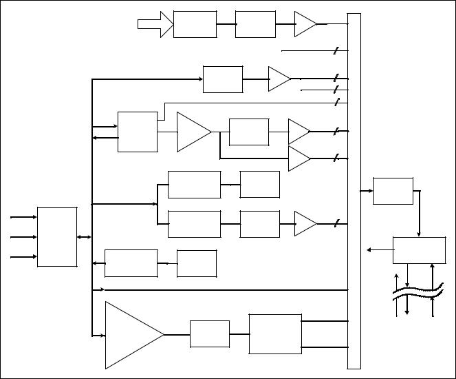
SC 6002XL Patient Monitor |
Field Service Manual |
|
|
|
|
NBP |
Pressure |
|
Low-Pass |
NBP |
|
|
|
|
|
Hose |
Transducer |
|
Filter |
Amp |
|
|
|
|
|
|
|
|
|
|
|||
|
|
|
|
|
|
Power Monitor |
4 |
|
|
|
|
|
Linearizer |
Amp |
Temp |
2 |
|
|
|
|
|
|
Temp Ref. |
2 |
|
|
|||
|
|
|
|
|
|
|
|
||
|
|
|
|
|
|
|
6 |
|
|
|
|
RF Filter |
|
|
|
ECG |
4 |
|
|
|
|
Lead Off |
Pre- |
Bandpass |
|
|
|||
|
|
Amp |
|
|
|
||||
|
|
Neutral |
Amp |
|
Filter |
|
|
|
|
|
|
|
|
|
|
|
|||
|
|
SW |
|
|
|
Pace |
2 |
|
|
|
|
|
|
|
|
|
|
||
|
|
|
|
|
|
Amp |
|
|
|
|
|
|
Modulator |
|
Current |
|
M |
16 Bit |
|
|
|
|
|
Sources |
|
||||
|
|
|
|
|
U |
A / D |
|||
|
|
|
|
|
|
||||
|
|
|
|
|
|
|
|||
|
|
|
|
|
|
|
X |
Converter |
|
Temp |
MultiMed |
|
|
|
Bandpass |
Resp |
2 |
|
|
|
|
Demodulator |
|
|
|
||||
ECG |
Defib |
|
|
Filter |
Amp |
|
|
|
|
|
|
|
|
|
|
|
|||
Resp |
Protection |
|
|
|
|
|
|
Control |
Asic |
SpO 2 |
ESU |
Modulator |
LED Drive |
|
|
|
|
|
Data Control |
|
|
|
|
|
|
|
|||
|
|
|
|
|
|
Cal Resistor |
|
Power |
|
|
|
|
|
|
|
Red |
|
|
|
|
|
Differential |
Ambient |
|
|
|
|
|
HDLC |
|
|
Light |
|
Demodulator |
|
|
(to MPC821) |
||
|
|
I/V |
|
|
|
||||
|
|
Converter |
Rejection |
|
|
I/R |
|
|
|
|
|
|
|
|
|
|
|
||
Figure 2-2 Front End
5Physiological Parameter Data Acquisition
Transducers gather physiological data at the patient and feed them into the small MultiMed Pod at the bed. The MultiMed Pod in turn is connected via a 3-meter cable to the front end in the main unit where analog ECG, Respiration, Temperature, and SpO2 signals are converted to digital form and sent through isolators for processing.
5.1 ECG/Resp |
The MultiMed Pod located close to the patient accepts a set of 3, 5 or 6 |
||
|
shielded ECG electrode leads, an SpO2 (Nellcor) cable adapter, and a |
||
|
temperature sensor. The ECG section contains RF filters, and overvoltage |
||
|
clamps that include 1k series resistors to limit shunting of defibrillator |
||
|
current. The SpO2 and temperature sections also contain RF filters. |
||
|
Impedance respiration is sensed through the ECG electodes. Void-free |
||
|
potting and internal shielding enable compact containment of high voltage |
||
|
defibrillator and electrosurgery pulses. The small interconnecting cable to |
||
|
the main assembly is captive at the MultiMed POD but plugs into the |
||
|
MultiMed front end via a specially shielded connector. |
|
|
|
The front end accepts physiological signals from the MultiMed POD |
||
|
connector and feeds temperature, respiration, and ECG signals via RF |
||
|
filters, configuration multiplexers, and pre-amplifiers to a high-speed |
||
|
|
|
|
12 |
Siemens Medical Systems, EM-PCS, Danvers |
ASK-T941-04-7600 |
|
6k2XLSMC2.cd-rom.fm/06-00/kaupp
Field Service Manual |
SC 6002XL Patient Monitor |
|
|
multiplexer driving a 16-bit analog-to-digital (A/D) converter. The data stream is sent to the Main Processor board via an opto-isolator. Control commands from the Processor are sent out to the front end on a similar isolating link. Isolated DC power is also provided.
The ECG signals are conductively coupled to the isolated circuits via current-limiting series resistors, whereas the SpO2 signals are optically isolated at the transducer. Temperature signals are doubly insulated at the patient by disposable boots on the sensors. AC (40kHz) excitation currents for respiration monotoring are dc-isolated by high-voltage ceramic capacitors.
The A/D samples the following parameters:
Table 2-1 Parameter Sampling Table
|
|
|
|
Parameter |
# of Channels |
|
|
|
|
ECG |
4 |
|
|
|
|
Pace |
2 |
|
|
|
|
SpO2 Red |
1 |
|
SpO2 IR |
1 |
|
NBP |
1 |
|
|
|
|
Resp |
1 |
|
|
|
|
Temp |
2 |
|
|
|
|
|
|
|
The hardware pace detector monitors the ECG signal in two of the four |
|
channels (those not connected to the chest leads). All other signals are |
|
decimated and filtered using digital signal processing in the MPC821. High |
|
oversampling rate is required to minimize the requirements (and size) of |
|
the analog anti alias filters. Superior rejection to ESU and other types of |
|
interference is achieved with this type of design. |
5.1.1 ECG |
• Bandwidth is set flexibly by software filters. |
|
• Reconfigurable neutral selector can drive any electrode. |
|
• Lead-on detection functions with even poor electrodes. |
• Calibration voltages can be superimposed on patient wave-forms or onto flat baselines.
See Figure 2-3. Composite electrocardiographic (ECG) signals generated by the heart and by a pacemaker are filtered to reduce RF interference from impedance respiration and electrosurgery and then injected with dc lead-off detection currents. Over-voltage clamps protect the semiconductors from the surges passing the sparkgaps in the MultiMed Pod and also reduce the dc current applied to the patient due to a component fault.
ASK-T941-04-7600 |
Siemens Medical Systems, EM-PCS Danvers |
13 |
6k2XLSMC2.cd-rom.fm/06-00/kaupp

SC 6002XL Patient Monitor |
Field Service Manual |
|
|
RA |
LA |
aVR |
aVL |
|
aVF |
|
LL |
Figure 2-3 Lead-Forming Network
5.1.2 |
Lead Selection |
A lead-forming network following the RF filter generates the necessary |
|
|
reference points for electrocardiographic measurements. Both normal |
|
|
leads (I, II, III, V1 and V2) and augmented leads (aVL, avR, and avF) can be |
|
|
obtained. See Figure 2-3. |
|
|
Four differential channels generate the main axes I, II, V1 and V2. The |
|
|
remaining leads are derived mathematically as indicated in the vector |
|
|
diagram of Figure 2-3. |
5.1.3 |
Lead-Off Detection |
Lead-off detection is accomplished by introducing a very small current into |
|
|
each patient electrode, which would drive the corresponding input high if |
|
|
it were disconnected. A set of five comparators detects a lead-off |
|
|
condition. |
5.1.4Low-Pass Filtering and Common Mode Enhancement
The ECG preamplifier has a flat frequency response of 0.5 - 40Hz, with a software notch filter at 50/60 Hz. A 180° combined signal drives the neutral electrode to increase the CMMR.
14 |
Siemens Medical Systems, EM-PCS, Danvers |
ASK-T941-04-7600 |
6k2XLSMC2.cd-rom.fm/06-00/kaupp

Field Service Manual |
SC 6002XL Patient Monitor |
|
|
5.2 Respiration
Impedance respiration is monitored by injecting a 40 kHz square wave of current into the RA electrode. The resulting 40 kHz voltage drop between the RA + LL electrodes is proportional to the impedance. Especially balanced true current sources do not load the ECG electrodes or distort the ECG morphology. The returning 40 kHz differential voltage is amplified, synchronously demodulated, and low-pass filtered. An AC-coupled stage with an “autobloc” DC restorer feeds the input to the A/D converter with a nominal output of 60 mV per Ohm.
5.3 SpO2
5.3.1 SpO2 Front End
Figure 2-4 |
SpO2 Functional Block Diagram |
The pulse oximeter circuit uses a Nellcor® sensor to detect the oxygen saturation level in arterial blood flow. Determination of the concentration of oxygen in the blood is based upon the principle that the absorption of red (R) light depends on the degree of oxygenation of the blood, whereas the absorption of infrared (IR) radiation is relatively independent of oxygenation and causes only constant attenuation. See Figure 2-4. In the SpO2 sensor, R and IR light emitting diodes (LEDs) are alternately pulsed ON at a 25% duty cycle. The light is transmitted through a well-perfused part of the body, such as a fingertip or an ear lobe. The intensity of light (including ambient) transmitted through or scattered by the blood is converted to a current by a photodiode in the sensor. The current that appears when both LEDs are OFF depends mainly on the ambient light, which is later subtracted to leave only the R or IR signal levels. The large dynamic range of the light intensities requires constant automatic monitoring and adjustment.
The intensities of the R and IR sources are independently controlled by two digital-to-analog converters (DACs) attenuating the 2.5 V reference. These levels or zero are sequentially selected by a multiplexer, and converted to a driving current which is further guided or inverted by an output multiplexer to the LEDs in the sensor.
The primary purpose of the SpO2 front end is to convert the sensor’s analog signal into individual digitized signals for the red and infrared analog signals for processing by the microprocessor. See Figure 2-5 on page 16. Circuitry in the front end first eliminates the non-pulsatile component in the input signal, then demultiplexes the resulting pulsatile signal to separate the R and IR signal components, and finally converts the demultiplexed R and IR analog signals into serial digital data streams.
A sequence of light pulses, driven from the chopped current source in the sensor LEDs, are passed through a finger or an earlobe to a photodiode. The sensor LEDs are connected in an anti-parallel fashion on one pair of wires.
ASK-T941-04-7600 |
Siemens Medical Systems, EM-PCS Danvers |
15 |
6k2XLSMC2.cd-rom.fm/06-00/kaupp
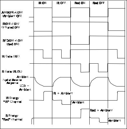
SC 6002XL Patient Monitor |
Field Service Manual |
|
|
5.3.2Input Stage
5.3.3Brightness Control
5.3.4Ambient Light Rejection Amplifier
Figure 2-5 |
Sensor LED Timing Diagram |
A timing generator controls the sensor LEDs and signal multiplexing/ demultiplexing (see Figure 2-5) by means of three control signals:
•IRONL (infrared LED)
•AMBONL (LEDS not lit)
•REDONL (red LED)
A preamplifier converts the photocurrent to an equivalent voltage, and applies it to a 20 Hz high-pass filter that removes the non-pulsatile component. The output of the preamplifier is fed to a saturation detector.
If the output of the preamplifier is in saturation, the gate array provides a signal to the digital-to-analog converters (DACs), which controls the drive current to increase or decrease the brightness of the LEDs.
Controlling LED brightness extends the system dynamic range. For a very transparent subject it may not be possible to reduce the gain to prevent saturation. In that event, the brightness must be reduced. An additional purpose is to equalize the received amplitude of each wavelength. If both LEDs are turned ON to maximum brightness, and the software finds an extraordinary difference between the two, the microprocessor tends to reduce that difference by equalizing the R or IR brightness signals.
The ambient rejection amplifier is a synchronous detector. The signal appied to its inverting input is a composite of R, IR, and ambient signals. The non-inverting input is the same signal gated by the timing generator. This synchronously multiplexes the IR, ambient, and R analog signals.
16 |
Siemens Medical Systems, EM-PCS, Danvers |
ASK-T941-04-7600 |
6k2XLSMC2.cd-rom.fm/06-00/kaupp
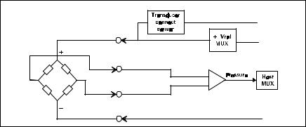
Field Service Manual |
SC 6002XL Patient Monitor |
|
|
5.4Invasive Blood Pressure
5.5Non-Invasive Blood Pressure
5.5.1 NBP Subsystem
|
+2.6V |
|
-2.6V |
Figure 2-6 |
IBP Functional Block Diagram |
The IBP circuit has been designed to be used with a strain gauge pressure transducer. See Figure 2-6. The analog portion of the IBP circuit provides excitation voltages for resistance bridge transducers. These voltages are derived from a reference which is also used to derive the A/D converter reference voltage. At the circuit input, a resistor divider network provides for transducer unplugged detection. R-C filtering and protection diodes limit the effects produced during electrosurgery, defibrillation, and other such procedures. A selector multiplexer allows for the insertion of calibration signals into the amplifier stage. The multiplexor feeds the pressure signal to a buffer amplifier, which in turn feeds the AD converter analog input. This allows the monitor to measure pressure signals in a range greater than ±700 mmHg with a resolution of approximately
.02mmHg/LSB.
When no pressure transducer is plugged into the monitor, the resistor divider network puts a negative signal into the instrumentation amplifier, which propagates through the system to indicate the unplugged condition.
Refer to Figure 2-7 on page 18.
The NBP subsystem consists of the following components:
•pump
•two modulating valves
•strain-gauge pressure transducer
•overpressure sensor
•pneumatic manifold
In addition, an electronic data acquisition and control system measures and digitizes the pressure pulses as the cuff inflates and deflates. Pump and valve control circuitry engage these elements as needed in the measurement cycle. Several interlock systems and expiration timers ensure the safety of the equipment in case of single point failures.
The SC6002XL NBP circuit uses a cuff and the oscillometric method to determine blood pressure without using a microphone. A strain-gauge pressure transducer is DC-coupled to a 16-bit A/D converter, so that cuff pressure is measured with adequate resolution to detect blood pressure pulses. This eliminates the need for a separate ac-coupled measurement channel, with its associated distortion and long transient recovery.
ASK-T941-04-7600 |
Siemens Medical Systems, EM-PCS Danvers |
17 |
6k2XLSMC2.cd-rom.fm/06-00/kaupp
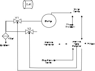
SC 6002XL Patient Monitor |
Field Service Manual |
|
|
|
|
|
|
|
|
|
|
|
|
|
|
|
|
|
|
|
|
|
|
|
|
|
|
|
|
|
|
|
|
|
|
|
|
|
|
|
|
|
|
|
|
|
|
|
|
|
|
|
|
|
|
|
|
|
|
|
|
|
|
|
|
|
|
|
|
|
|
|
|
|
|
|
|
|
|
|
|
|
|
|
|
|
|
|
|
|
|
|
|
|
|
|
|
|
|
|
|
|
|
|
|
|
|
|
|
|
|
|
|
|
|
|
|
|
|
|
|
|
|
|
|
|
|
|
|
|
|
|
|
|
|
|
|
|
|
|
|
|
|
|
|
|
|
|
|
|
|
|
|
|
|
|
|
|
|
|
|
|
|
|
|
|
|
|
|
|
|
|
|
|
|
|
|
|
|
|
|
|
|
|
|
|
|
|
|
|
|
|
|
|
|
|
|
|
|
|
|
|
|
|
|
|
|
|
|
|
|
|
|
|
|
|
|
|
|
|
|
|
|
|
|
|
|
|
|
|
|
|
|
|
|
|
|
|
|
|
|
|
|
|
|
|
|
|
|
|
|
|
|
|
|
|
|
|
|
|
|
|
|
|
|
|
|
|
|
|
|
|
|
|
|
|
|
|
|
|
|
|
|
|
|
|
|
|
|
|
|
|
|
|
|
|
|
|
|
|
|
|
|
|
|
|
|
|
|
|
|
|
|
|
|
|
|
|
|
|
|
|
|
|
|
|
|
|
|
|
|
|
|
|
|
|
|
|
|
|
|
|
|
|
|
|
|
|
|
|
|
|
|
|
|
|
|
|
|
|
|
|
|
|
|
|
|
|
|
|
|
|
|
|
|
|
|
|
|
|
|
|
|
|
|
|
|
|
|
|
|
|
|
|
|
|
|
|
|
|
|
|
|
|
|
|
|
|
|
|
|
|
|
|
|
|
|
|
|
|
|
|
|
|
|
|
|
|
|
|
|
|
|
|
|
|
|
|
|
|
|
|
|
|
|
|
|
|
|
|
|
|
|
|
|
|
|
|
|
|
|
|
|
|
|
|
|
|
|
|
|
|
|
|
|
|
|
|
|
|
|
|
|
|
|
|
|
|
|
|
|
|
|
|
|
|
|
|
|
|
|
|
|
|
|
|
|
|
|
|
|
|
|
|
|
|
|
|
A/D |
|
|
|
|
|
|
|
|
|
|
|
|
|
|
|
|
|
|
|
|
|
|
|
|
|
|
|
|
|
|
|
|
|
|
|
|
|
|
|
|
|
|
|
|
|
|
|
|
|
|
|
|
|
|
|
|
|
|
|
|
|
|
|
|
|
|
|
|
|
|
|
|
|
|
|
|
|
|
|
|
|
|
|
|
|
|
|
|
|
|
|
|
|
|
|
|
|
|
|
|
|
|
|
|
|
|
|
|
|
|
|
|
|
|
|
|
|
|
|
|
|
|
|
|
|
|
|
|
|
|
|
|
|
|
|
|
|
|
|
|
|
|
|
|
|
|
|
|
|
|
|
|
|
|
|
|
|
|
|
|
|
|
|
|
|
|
|
|
|
|
|
|
|
|
|
|
|
|
|
|
|
|
|
|
|
|
|
|
|
|
|
|
|
|
|
|
|
|
|
|
|
|
|
|
|
|
|
|
|
|
|
|
|
|
|
|
|
|
|
|
|
|
|
|
|
|
|
|
|
|
|
|
|
||||||||||||||||||||||||||||||
|
|
|
Figure 2-7 NBP Functional Block Diagram |
|
|
|
|
|
|
|||||||||||||||||||||||||||||||
5.5.2 |
NBP System Description |
The combination of high-resolution A/D conversion and digital filtering, |
||||||||||||||||||||||||||||||||||||||
|
|
|
together with wide-range linear deflation control allows the circuit to |
|||||||||||||||||||||||||||||||||||||
|
|
|
measure blood pressure very rapidly and accurately, and to recover quickly |
|||||||||||||||||||||||||||||||||||||
|
|
|
from motion artifacts. The non-invasive pressure system is composed of |
|||||||||||||||||||||||||||||||||||||
|
|
|
the following components: |
|
|
|
|
|
|
|||||||||||||||||||||||||||||||
|
|
|
• pneumatic assembly |
|
|
|
|
|
|
|||||||||||||||||||||||||||||||
|
|
|
• electronic circuitry, mounted on the Main CPU Board |
|
|
|
|
|
|
|||||||||||||||||||||||||||||||
|
Pneumatic Assembly |
|
The pneumatic assembly contains a pump, two modulating valves (V1 and |
|||||||||||||||||||||||||||||||||||||
|
|
|
V2), two air filters (intake and manifold), and a manifold assembly which |
|||||||||||||||||||||||||||||||||||||
|
|
|
interconnects these components. The pump provides the pressurized air |
|||||||||||||||||||||||||||||||||||||
|
|
|
to inflate the blood pressure cuff. V1 and V2 control the air flow during the |
|||||||||||||||||||||||||||||||||||||
|
|
|
deflation phase of a blood pressure measurement. V1 is a normally-closed |
|||||||||||||||||||||||||||||||||||||
|
|
|
exhaust valve with a relatively small orifice (relative to V2). V2 is a normally- |
|||||||||||||||||||||||||||||||||||||
|
|
|
open exhaust valve with a relatively large orifice. The pump speed can be |
|||||||||||||||||||||||||||||||||||||
|
|
|
controlled to permit accurate inflation pressures for special applications. |
|||||||||||||||||||||||||||||||||||||
|
|
|
The filters prevent potential contamination of pneumatic components by |
|||||||||||||||||||||||||||||||||||||
|
|
|
debris coming from the cuff or hose. |
|
|
|
|
|
|
|||||||||||||||||||||||||||||||
|
Electronic Circuitry |
|
The electronic circuitry, mounted on the Main CPU Board, contains the |
|||||||||||||||||||||||||||||||||||||
|
|
|
electrical drivers for the pump, the valves, and its power supplies. In |
|||||||||||||||||||||||||||||||||||||
|
|
|
addition, the readback from the pressure transducer is processed through |
|||||||||||||||||||||||||||||||||||||
|
|
|
the floating section ADC. The software data acquisition and algorithm |
|||||||||||||||||||||||||||||||||||||
|
|
|
processing is performed in the MPC821 main processor. |
|
|
|
|
|
|
|||||||||||||||||||||||||||||||
5.5.3 |
Operation |
The measurement sequence consists of an inflation phase, in which the air |
||||||||||||||||||||||||||||||||||||||
|
|
|
pump inflates the cuff, which has been wrapped around the patient’s limb |
|||||||||||||||||||||||||||||||||||||
|
|
|
(typically the upper arm or thigh) to a predetermined pressure. At this |
|||||||||||||||||||||||||||||||||||||
|
|
|
point, the blood circulation to the limb is occluded. The monitor then |
|||||||||||||||||||||||||||||||||||||
|
|
|
linearly deflates the cuff at a software-controlled rate during which time |
|||||||||||||||||||||||||||||||||||||
|
|
|
the blood pressure parameters are determined by digital filtering and |
|||||||||||||||||||||||||||||||||||||
|
|
|
analysis of waveform data obtained from the pressure transducer during |
|||||||||||||||||||||||||||||||||||||
|
|
|
the deflation cycle. |
|
|
|
|
|
|
|||||||||||||||||||||||||||||||
|
|
|
|
|
|
|
|
|
|
|
|
|
|
|
|
|
|
|
|
|
|
|
|
|
|
|
|
|
|
|
|
|
|
|
|
|
|
|
|
|
18 |
|
Siemens Medical Systems, EM-PCS, Danvers |
ASK-T941-04-7600 |
|
||||||||||||||||||||||||||||||||||||
6k2XLSMC2.cd-rom.fm/06-00/kaupp
|
Field Service Manual |
SC 6002XL Patient Monitor |
||
|
|
|
|
|
|
|
Inflation Phase |
When a blood pressure measurement is initiated (via software or front |
|
|
|
|
panel fixed key), V2 closes, the pump turns ON, and the pressure |
|
|
|
|
transducers monitor the ensuing pressure rise. When the pressure has |
|
|
|
|
reached the target inflation pressure, the pump turns OFF and a dynamic |
|
|
|
|
braking circuit rapidly brings the pump to a halt. The target inflation |
|
|
|
|
pressure adapts to the patient’s systolic pressure, just occluding the blood |
|
|
|
|
flow. The software monitors the slope of the pressure curve during |
|
|
|
|
inflation to estimate the cuff volume, a factor used in the deflation |
|
|
|
|
sequence. |
|
|
|
Deflation Phase |
After the pump stops, there is a short delay to allow thermal transients to |
|
|
|
|
settle. Either V1 or V2 is modulated to control the deflation rate. The choice |
|
|
|
|
of V1 or V2 and the initial pulse width is made based on the estimated cuff |
|
|
|
|
volume determined during the inflation cycle. The chosen valve is |
|
|
|
|
modulated at a 20 Hz rate, and the pulse width (open time) is continuously |
|
|
|
|
adjusted to provide a linear deflation rate. If initial deflation was started with |
|
|
|
|
V1, the software may determine that it needs to switch to V2 to maintain |
|
|
|
|
proper deflation. In either case, V2 opens fully (de-energizes) when the |
|
|
|
|
measurement cycle is ended to allow for rapid and complete deflation. |
|
5.5.4 |
NBP Hardware |
Pump control circuitry provides the following three functions: |
|
|
|
|
|
• limits the current to the pump when it starts, to prevent power supply |
|
|
|
|
overload |
|
|
|
|
• dynamically brakes the pump when the pump is shut off |
|
|
|
|
• provides a closed-loop speed control for special low-flow operations |
|
|
|
Speed Control |
Pump speed is controlled by measuring the back-EMF generated by the |
|
|
|
|
motor winding, which is directly proportional to the speed. However, to |
|
|
|
|
obtain a measurement of the back-EMF, the drop caused by copper losses |
|
|
|
|
must be added to the voltage appearing on the motor winding. The speed |
|
|
|
|
control effectively drives the pump at constant full speed. |
|
|
|
Current Limit |
Dedicated circuitry limits the current to the pump. When the current on the |
|
|
|
|
pump is approx. 363 mA, the current loop takes over and limits its value. |
|
|
|
|
The microprocessor and an N-channel FET turn the pump ON. |
|
5.5.5 |
Valve Control |
A relatively high pulse voltage is used to drive V1 and V2 to get quick |
|
|
|
|
|
response and extend the pulse-width flow control range. |
|
5.5.6 |
Power Supplies |
Separate control logic supplies voltage (+12V) to the pump and V2 to |
|
|
|
|
|
provide them with redundant turn-off capability. Without +12V the pump |
|
|
|
|
cannot run, and V2 can neither close nor remain closed. Power supplies |
|
|
|
|
necessary for operation of the NBP circuitry are derived as follows: |
|
|
|
+5V and -5V Supply |
The +5V and -5V for the NBP analog circuitry are derived from the floating |
|
|
|
|
section. |
|
|
|
+12V Supply |
The +12V drives the NBP pump and both modulating valves. The 6002XL |
|
|
|
|
flyback supply produces the +12V. This circuit produces several voltages |
|
|
|
|
needed for monitor operation. The main flyback regulation loop is closed |
|
|
|
|
around the +12V output, therefore making it the best regulated of the |
|
|
|
|
multiple voltages generated. |
|
|
|
|
In operation, a resistor network samples the +12V output and feeds it into |
|
|
|
|
the controller chip error amplifier, which compares it to an internal |
|
|
|
|
reference. The duty cycle of the switching transistor is adjusted to null this |
|
|
|
|
reference. A separate current feedback loop is used to stabilize the circuit |
|
|
|
|
and provide current limiting protection. |
|
|
|
|
||
ASK-T941-04-7600 |
Siemens Medical Systems, EM-PCS Danvers |
19 |
||
6k2XLSMC2.cd-rom.fm/06-00/kaupp
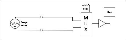
SC 6002XL Patient Monitor |
Field Service Manual |
|
|
|
|
|
+36V Regulator |
A +36V supply used to accelerate the energizing of the valve coils is |
|
|
derived from the 42V raw supply generated by the flyback supply. |
5.5.7 |
Power Supply Monitor |
The power supply monitor circuit provides reset logic to the |
|
|
microprocessor, and the redundant power switch circuit, both at power-up |
|
|
and in the event of a power failure or voltage drop. The heart of the monitor |
|
|
is a power supervisor chip. At power-up, the control line is held low for a |
|
|
period of about 200 ms, after which the voltage rises to the +5V level. After |
|
|
start-up, any dip in the +5V that causes the output to go to less than |
|
|
+4.75V causes the same sequence. A resistor network is used to monitor |
|
|
the +12V supply. When the voltage on the reference signal falls below |
|
|
+1.25V, a reset sequence similar to the one described above ensues. The |
|
|
+5V and -5V are monitored via the floating section ADC. |
5.5.8 |
Safety Timer |
The safety timer becomes active only after starting the pump at least one |
|
|
time. Once the pump has been activated, the timer circuit operates |
|
|
regardless of whether the pump has been turned off. Starting of the pump |
|
|
is sensed by voltage developed across the pump sense resistor. If as a result |
|
|
of some failure, hardware or software, the pump continues to run longer |
|
|
than the timer expiration period, a microcontroller output rises and opens a |
|
|
redundant switch, which causes the pump to turn off and V2 to open. |
The safety timer period is derived from the microcontroller clock. Note that, for redundancy purposes, the safety timer is implemented not in the MPC821 but in the 68HC11 microcontroller.
Among other signals multiplexed into the floating section data stream are power supply monitor voltages. Measuring these voltages gives an indication of the integrity of the power supplies and the A/D converter voltage reference.
5.5.9 Pressure Channels |
Pressure fluctuations in the cuff change the balance of the pressure |
|
measurement bridge, resulting in a differential voltage which is fed into an |
|
amplifier. The gain of the amplifier is determined by the setting of a |
|
calibration potentiometer. This potentiometer is initially adjusted in the |
|
factory, and from then on the calibration should be checked every year. |
The overpressure hardware is fed by a single power source. This increases safety of the system, since a failure of the reference voltages does not impact operation of the overpressure channel. An overpressure test is performed at each power-up cycle to ensure that the overpressure circuitry is working. Any error detected in the overpressure comparator circuit is fed to the redundant power switch circuitry described above. The software overpressure detection is completely independent of the overpressure circuitry.
Figure 2-8Temperature Functional Block Diagram |
5.6 Temperature Circuit
Temperature measurements are made using a thermistor probe that is electrically equivalent to YSI 400 series probes. See Figure 2-8.
20 |
Siemens Medical Systems, EM-PCS, Danvers |
ASK-T941-04-7600 |
6k2XLSMC2.cd-rom.fm/06-00/kaupp
Loading...