


G2201
|
|
|
|
REV13.. |
Installationsanleitung |
Installation instructions |
Instructions d’installation |
||
Istruzioni di montaggio |
Montage instructie |
Instrucciones de montaje |
||
Instruções de montagem |
Návod k montáži a uvední do provozu |
Telepítési leírás |
||
Instrukcja montażu i uruchomienia |
Installationsanvisning |
Asennusohje |
||
Installationsvejledning |
tr Kurulum talimatlari |
Οδηγίες εγκατάστασης |
||
|
|
|
|
|
A |
|
|
|
D |
|
|
|
|
|
E
B
C
F
CE1G2201xx |
08.02.2008 |
1/40 |

G
 / 1.1.1
|
|
|
|
|
DIP Switch 1: OFF |
|
|
DIP Switch 1: ON |
|
||||||||||||||||||||||||||||||||||||||||||||||||||||||||||||
|
|
|
|
|
|
|
|
|
|
|
|
|
|
|
|
|
|
|
|
|
|
|
|
|
|
|
|
|
|
|
|
|
|
|
|
|
|
|
|
|
|
|
|
|
|
|
|
|
|
|
|
|
|
|
|
|
|
|
|
|
|
|
|
|
|
|
|
|
|
|
|
|
|
|
|
|
|
|
|
|
|
|
|
|
|
|
|
|
|
|
|
|
|
|
|
|
|
|
|
|
|
|
|
|
|
|
|
|
|
|
|
|
|
|
|
|
|
|
|
|
|
|
|
|
|
|
|
|
|
|
|
|
|
|
|
|
|
|
|
|
|
|
|
|
|
|
|
|
|
|
|
|
|
|
|
|
|
|
|
|
|
|
|
|
|
|
|
|
|
|
|
|
|
|
|
|
|
|
|
|
|
|
|
|
|
|
|
|
|
|
|
|
|
|
|
|
|
|
|
|
|
|
|
|
|
|
|
|
|
|
|
|
|
|
|
|
|
|
|
|
|
|
|
|
|
|
|
|
|
|
|
|
|
|
|
|
|
|
|
|
|
|
|
|
|
|
|
|
|
|
|
|
|
|
|
|
|
|
|
|
|
|
|
|
|
|
|
|
|
|
|
|
|
|
|
|
|
|
|
|
|
|
|
|
|
|
|
|
|
|
|
|
|
|
|
|
|
|
|
|
|
|
|
|
|
|
|
|
|
|
|
|
|
|
|
|
|
|
|
|
|
|
|
|
|
|
|
|
|
|
|
|
|
|
|
|
|
|
|
|
|
|
|
|
|
|
|
|
|
|
|
|
|
|
|
|
|
|
|
|
|
|
|
|
|
|
|
|
|
|
|
|
|
|
|
|
|
|
|
|
|
|
|
|
|
|
|
|
|
|
|
|
|
|
|
|
|
|
|
|
|
|
|
|
|
|
|
|
|
|
|
|
|
|
|
|
|
|
|
|
|
|
|
|
|
|
|
|
|
|
|
|
|
|
|
|
|
|
|
|
|
|
|
|
|
|
|
|
|
|
|
|
|
|
|
|
|
|
|
|
|
|
|
|
|
|
|
|
|
|
|
|
|
|
|
|
|
|
|
|
|
|
|
|
|
|
|
|
|
|
|
|
|
|
|
|
|
|
|
|
|
|
|
|
|
|
|
|
|
|
|
|
|
|
|
|
|
|
|
|
|
|
|
|
|
|
|
|
|
|
|
|
|
|
|
|
|
|
|
|
|
|
|
|
|
|
|
|
|
|
|
|
|
|
|
|
|
|
|
|
|
|
|
|
|
|
|
|
|
|
|
|
|
|
|
|
|
|
|
|
|
|
|
|
|
|
|
|
|
|
|
|
|
|
|
|
|
|
|
|
|
|
|
|
|
|
|
|
|
|
|
|
|
|
|
|
|
|
|
|
|
|
|
|
|
|
|
|
|
|
|
|
|
|
|
|
|
|
|
|
|
|
|
|
|
|
|
|
|
|
|
|
|
|
|
|
|
|
|
|
|
|
|
|
|
|
|
|
|
|
|
|
|
|
|
|
|
|
|
|
|
|
|
|
|
|
|
|
|
|
|
|
|
|
|
|
|
|
|
|
|
|
|
|
|
|
|
|
|
|
|
|
|
|
|
|
|
|
|
|
|
|
|
|
|
|
|
|
|
|
|
|
|
|
|
|
|
|
|
|
|
|
|
|
|
|
|
|
|
|
|
|
|
|
|
|
|
|
|
|
|
|
|
|
|
|
|
|
|
|
|
|
|
|
|
|
|
|
|
|
|
|
|
|
|
|
|
|
|
|
|
|
|
|
|
|
|
|
|
|
|
|
|
|
|
|
|
|
|
|
|
|
|
|
|
|
|
|
|
|
|
|
|
|
|
|
|
|
|
|
|
|
|
|
|
|
|
|
|
|
|
|
|
|
|
|
|
|
|
|
|
|
|
|
|
|
|
|
|
|
|
|
|
|
|
|
|
|
|
|
|
|
|
|
|
|
|
|
|
|
|
|
|
|
|
|
|
|
|
|
|
|
|
|
|
|
|
|
|
|
|
|
|
|
|
|
|
|
|
|
|
|
|
|
|
|
|
|
|
|
|
|
|
|
|
|
|
|
|
|
|
|
|
|
|
|
|
|
|
|
|
|
|
|
|
|
|
|
|
|
|
|
|
|
|
|
|
|
|
|
|
|
|
|
|
|
|
|
|
|
|
|
|
|
|
|
|
|
|
 / 1.1.3
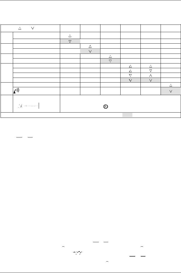
DIP Switch 3: OFF |
DIP Switch 3: ON |
|
|
 / 1.1.4
°C |
2211Z16 |
|

 t PID self-learning
°C |
2211Z16 |
|
|
|
t |
6 min |
PID 6 |
°C |
2211Z16 |
|
|
t |
12 min |
PID 12 |
°C |
2211Z16 |
0,5 °C |
|
|
t 2-Point |
 / 1.1.5
DIP Switch 6: OFF |
DIP Switch 6: ON |
|
|
 / 1.1.6
DIP-Switch-Reset
2/40 |
08.02.2008 |
CE1G2201xx |

Montagehinweise REV13..
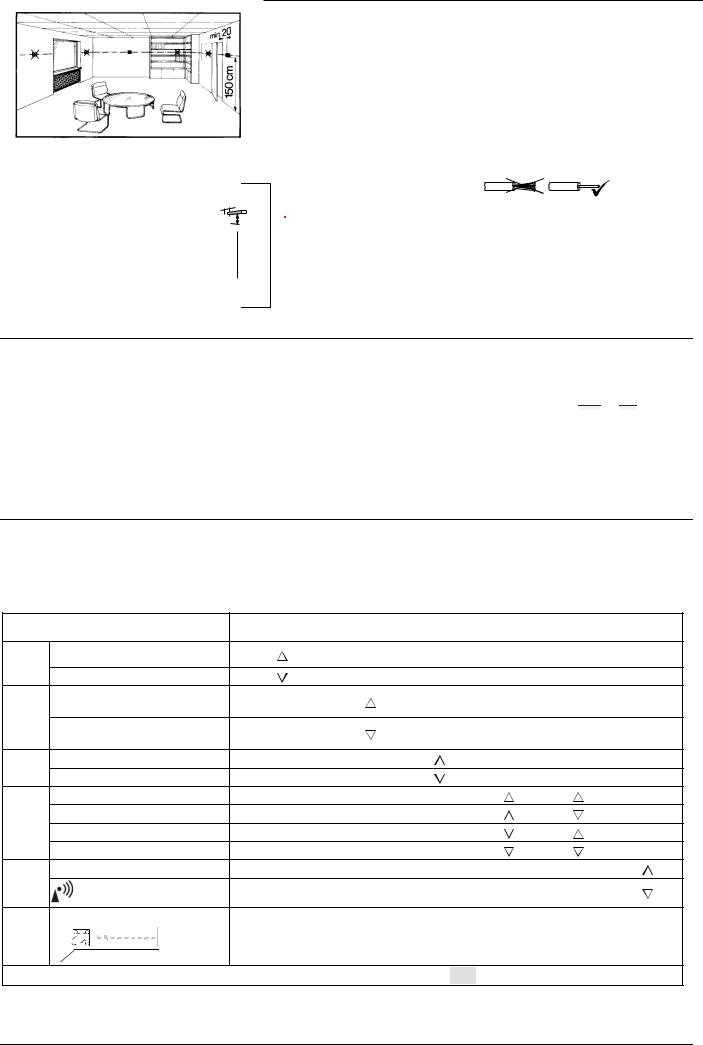
1 Platzierungshinweise
•Der REV13.. sollte im Hauptaufenthaltsraum platziert werden (Wandmontage Abb. B bis E).
•Der Platzierungsort des REV13.. ist so zu wählen, dass der Fühler die Lufttemperatur im Raum möglichst unverfälscht messen kann und nicht durch direkte Sonneneinstrahlung oder andere Wärmebzw. Kältequellen beeinflusst wird.
min. |
10 cm |
2261Z03
Inbetriebsetzung
1 REV13.. einschalten
•Schwarzen Isolierstreifen entfernen (Abb. F); sobald der Isolierstreifen am Batteriekontakt entfernt ist, ist das Gerät betriebsbereit (siehe auch Bedienungsanleitung)
2 Auswahl der Bediensprache
•Beim Aufstarten erscheint in der Anzeige oben links der Typ des Reglers und in der Textzeile die Willkommenslaufschrift “THANK YOU …“ in allen vorhandenen Sprachen
2 Montage
•Siehe Abb. A bis E
3 Verdrahtung prüfen
Die Anschlüsse sind im Kapitel „Anschlussschaltplan“ ersichtlich.
Hinweis: |
Keine Litzen verwenden, nur Volldraht |
|
oder Litzen mit Aderendhülsen! |
4 Hinweise
•Die örtlichen Vorschriften für Elektroinstallationen sind einzuhalten.
•Sollten im Referenzraum thermostatische Heizkörperventile installiert sein, müssen diese vollständig geöffnet werden
•Drücken Sie irgendeine Taste, um die Laufschrift abzubrechen. Die Auswahl der Bediensprache startet mit
“ENGLISH“ (Werkeinstellung). Drücken Sie auf  oder
oder
 , bis die gewünschte Bediensprache erscheint. Drücken Sie auf
  oder bewegen Sie den Schieber, um die gewählte Bediensprache zu bestätigen (siehe auch Abb. G)
Konfiguration und Funktionskontrolle REV13..
1 Konfiguration
1.1DIP-Schalter
 ON /
ON /  OFF
OFF
Siehe Fühlerkalibrierung ein
1.1.1Fühlerkalibrierung aus
1.1.2
Sollwertbegrenzung 16…35 °C
Sollwertbegrenzung 3…35 °C
1.1.3Temperaturanzeige °F Temperaturanzeige °C PID self-learning
1.1.4PID 6 PID12 2-Point
Quarz
1.1.5
Funkuhr
DIP Switch Reset
1.1.6 |
ON |
|
|
|
|
|
|
2211Z32 |
|
|
|
|
|
|
|
||
|
|
|
|
|
|
|
|
|
1 |
2 |
3 |
4 |
5 |
6 |
7 |
8 |
9 |
1 |
2 |
3 |
|
4 |
5 |
6 |
|
|
|
|
|
|
|
|
|
|
|
|
|
|
|
|
|
|
|
|
|
|
|
|
|
|
|
|
|
|
|
|
|
|
|
|
|
|
|
|
|
|
|
|
|
|
|
|
|
|
|
|
|
|
|
|
|
|
|
|
|
|
|
|
|
|
|
|
|
|
|
|
|
|
|
|
|
|
|
|
|
|
|
|
|
|
|
|
|
|
|
|
|
|
|
|
|
|
Nach Verändern einer oder mehrerer DIP-Schalter-Positionen muss durch Drücken des DIP-Schalter-Reset-Knopfes ein DIP-Schalter-Reset durchgeführt werden
(siehe auch Abb.  ). Andernfalls bleibt die vorherige Einstellung aktiv!
Werkeinstellung: Alle DIP-Schalter auf  OFF
OFF
CE1G2201xx |
08.02.2008 |
3/40 |

1.1.1 Fühlerkalibrierung: DIP-Schalter 1
DIP-Schalter auf ON und DIP-Schalter-Reset-Knopf drücken: CAL Symbol erscheint auf der Anzeige. Die aktuell gemessene Temperatur blinkt.
Durch Drücken auf  oder
oder  kann um max. ± 5 °C neu kalibriert werden. Zum Speichern der Eingabe DIP-Schalter auf
OFF und DIP-Schalter-Reset-Knopf drücken (siehe auch Abb.  ).
).
1.1.2 Sollwertbegrenzung: DIP-Schalter 2
DIP-Schalter ON: |
Sollwertbegrenzung 16…35 °C |
DIP-Schalter OFF: |
Sollwertbegrenzung 3…35 °C |
|
(Werkeinstellung) |
Eingabe speichern durch Drücken des DIP-Schalter-Reset-Knopfes.
1.1.3Temperaturanzeige in °C oder °F: DIP-Schalter 3
DIP-Schalter ON: |
Temperaturanzeige in °F |
DIP-Schalter OFF: |
Temperaturanzeige in °C |
|
(Werkeinstellung) |
Eingabe speichern durch Drücken des DIP-Schalter-Reset-Knopfes (siehe auch Abb.  ).
).
1.1.4 Regelverhalten: DIP-Schalter 4 und 5
DIP-Schalter 4 ON und 5 ON: PID self-learning Adaptive Steuerung für alle Anwendungen.
DIP-Schalter 4 ON und 5 OFF: |
PID 6 |
Schnelle Regelstrecke für Anwendungen an Orten mit grossen Temperaturschwankungen.
DIP-Schalter 4 |
OFF und 5 |
ON: |
PID 12 |
Normale Regelstrecke für Anwendungen an Orten mit |
|||
normalen Temperaturschwankungen. |
|||
DIP-Schalter 4 |
OFF und 5 |
OFF: |
2-PointFür schwierige |
Regelstrecken, reiner Zweipunktregler mit 0.5 C Schaltdifferenz. (Werkeinstellung).
Eingabe speichern durch Drücken des DIP-Schalter-Reset-Knopfes (siehe auch Abb.  ).
).
1.1.5 Funkuhr: DIP-Schalter 6
Nur anwendbar bei REV..DC (mit eingebautem DCF77 Empfänger für Zeitsignal Frankfurt)!
DIP-Schalter ON: |
Uhr läuft ab geräteinternem Quarz |
DIP-Schalter OFF: |
Zeitsignal DCF77 von Frankfurt |
Eingabe speichern durch Drücken des DIP-Schalter-Reset-Knopfes (siehe auch Abb.  ).
).
1.1.6 DIP-Switch Reset
Nach Verändern einer oder mehrerer DIP-Schalter-Positionen muss durch Drücken des DIP-Schalter-Reset-Knopfes ein DIP-Schalter- Reset durchgeführt werden.
Andernfalls bleibt die vorherige Einstellung aktiv!
(Siehe auch Abb.  )
)
2 Einstieg in die Fachmann-Einstellungen
Wahlschieber in RUN-Stellung und gleichzeitig  und
und  für 3 Sekunden drücken, Tasten loslassen und innerhalb 3 Sekunden gleichzeitig
  und
und  für 3 Sekunden gedrückt halten,
  loslassen und
  für weitere 3 Sekunden drücken. Die Fachmann-Einstellungen werden
freigegeben. 


 auf der Anzeige (siehe auch Abb. G).
Auf der Anzeige erscheint beginnend mit Code 00 die Auswahl der Sprachen. Navigation in den Fachmann-Einstellungen mit  oder
oder  . Einstellung mit
  bestätigen.
Ausstieg aus den Fachmann-Einstellungen durch Drücken der Betriebsartenwahltaste  .
.
Codeliste
Funktionsblock |
Code |
Name |
Werkeinstellung |
Ihre Einstellung |
Grundeinstellungen |
00 |
Sprache |
English |
|
01 |
Fühlerkalibrierung |
off |
|
|
|
02 |
Schaltdifferenz 2-Point |
0.5 °C |
|
|
|
|
|
|
LCD-Optimierung |
10 |
Beleuchtungszeit |
10 Sekunden |
|
11 |
Hintergrundhelligkeit |
0 |
|
|
|
12 |
Kontrast |
0 |
|
|
|
|
|
|
|
|
Zeitzone |
0 Stunden |
|
|
30 |
Abweichung zum Zeitsignal Frankfurt |
|
|
Einstellung Uhr |
|
(Mitteleuropäische Zeit MEZ) (siehe Hinweis 1) |
|
|
|
31 |
Start Sommerzeit (siehe Hinweis 2) |
31. März (31-03) |
|
|
32 |
Ende Sommerzeit (siehe Hinweis 3) |
31. Oktober (31-10) |
|
Hinweis 1:
Bei nicht aktiver oder nicht bestückter Funkuhr hat diese Eingabe keine Wirkung.
Bei aktiver Funkuhr wird das empfangene Zeitsignal aus Frankfurt um den unter Code 30 (Zeitzone) eingestellten Wert verschoben.
Hinweis 2:
Bei nicht aktiver oder nicht bestückter Funkuhr erfolgt der Zeitwechsel immer um 02:00 am Sonntag vor dem eingestellten Datum. Bei aktiver Funkuhr wird der Zeitwechsel um den unter Code 30 (Zeitzone) eingestellten Wert verschoben.
Hinweis 3:
Bei nicht aktiver oder nicht bestückter Funkuhr erfolgt der Zeitwechsel immer um 03:00 am Sonntag vor dem eingestellten Datum. Bei aktiver Funkuhr wird der Zeitwechsel um den unter Code 30 (Zeitzone) eingestellten Wert verschoben.
3 Funktionskontrolle
a)Anzeige kontrollieren. Erscheint keine Anzeige, muss der Einbau und die Funktion der Batterien geprüft werden
b)Betriebsart “Dauernd Komfortbetrieb“  , angezeigte Temperatur ablesen
c)Temperatursollwert höher als angezeigte Raumtemperatur einstellen (siehe Bedienungsanleitung)
d)Das Relais und somit das Stellgerät müssen spätestens nach einer Minute schalten. Das Symbol ▲ erscheint auf dem Display. Ist dies nicht der Fall:
•Stellgerät und Verdrahtung prüfen
•Eventuell ist die Raumtemperatur höher als der eingestellte Temperatursollwert
e)Temperatursollwert der Betriebsart “Dauernd Komfortbetrieb“  auf den gewünschten Wert einstellen
f)Gewünschte Betriebsart wählen
4/40 |
08.02.2008 |
CE1G2201xx |

4 Reset
Benutzerdefinierte Einstellungen:
 ,
,  und
und  gleichzeitig für 3 Sekunden drücken:
Alle Temperaturund Zeiteinstellungen am Programmwahlschieber werden auf Standardwerte zurückgesetzt (siehe auch Abschnitt „Werkeinstellungen“ in der Bedienungsanleitung). Die FachmannEinstellungen bleiben unverändert.
Die Uhr beginnt bei 12:00, das Datum bei 01-01-08
(01 - Januar - 2008). Während der Resetzeit leuchten alle Anzeigefelder des Displays und können so überprüft werden.
Alle benutzerdefinierten Einstellungen plus FachmannEinstellungen:
Mounting notes REV13..
1 Placement of unit
•The REV13.. should be mounted in the main living room (for wall mounting, refer to Figs. B through E)
•The REV13.. must be located such that it can acquire the room temperature as accurately as possible, without getting affected by direct solar radiation or other heat or refrigeration sources
min. |
10 cm |
2261Z03
Commissioning
1 Switching on the REV13..
•Remove the black battery transit tab (Fig. F); as soon as the tab is removed, the unit is ready to operate (also refer to operating instructions)
2 Selecting the language
•When starting up, the display shows the type of controller at top left and “THANK YOU …“ in all available languages on the text line
DIP-Schalter-Reset-Knopf,  und
und  gleichzeitig für 5 Sekunden drücken:
Nach diesem Reset werden alle Werkeinstellungen neu geladen. Dies gilt sowohl für den Programmwahlschieber als auch für die Fachmann-Einstellungen.
Hinweise
•Der Regler gehört zur Softwareklasse A und ist für den Gebrauch in einer Umgebung mit normalem Verschmutzungsgrad vorgesehen
2 Mounting
•Refer to Figs. A through E
3 Checking the wiring
For electrical connections, refer to “Connection diagram”.
Note: Do not use stranded wires, only solid wires or stranded wires with ferrules!
4 Notes
•The local regulations for electrical installations must be complied with
•If the reference room is equipped with thermostatic radiator valves, they must be set to their fully open position
•Press one of the buttons to stop the running display. The choice of languages starts with “ENGLISH“ (factory setting).
Press  or
or  until the language you require appears. Press
  or move the slider to confirm the selected language (also refer to Fig. G)
Configuration and function check REV13..
1 Configuration
1.1DIP switches
|
|
ON / OFF |
1 |
|
2 |
3 |
4 |
5 |
6 |
|
|
|
|
|
|
|
|
|
|
|
|
|
See |
Sensor calibration on |
|
|
|
|
|
|
|
|
|
1.1.1 |
|
|
|
|
|
|
|
|
|
|
Sensor calibration off |
|
|
|
|
|
|
|
|
|
|
|
|
|
|
|
|
|
|
|
|
|
1.1.2 |
Setpoint limitation 16…35 °C |
|
|
|
|
|
|
|
|
|
Setpoint limitation 3…35 °C |
|
|
|
|
|
|
|
|
|
|
|
|
|
|
|
|
|
|
|
|
|
1.1.3 |
Temperature display °F |
|
|
|
|
|
|
|
|
|
Temperature display °C |
|
|
|
|
|
|
|
|
|
|
|
|
|
|
|
|
|
|
|
|
|
|
PID self-learning |
|
|
|
|
|
|
|
|
|
1.1.4 |
PID 6 |
|
|
|
|
|
|
|
|
|
PID12 |
|
|
|
|
|
|
|
|
|
|
|
|
|
|
|
|
|
|
|
|
|
|
2-Point |
|
|
|
|
|
|
|
|
|
1.1.5 |
Quartz |
|
|
|
|
|
|
|
|
|
Radio clock |
|
|
|
|
|
|
|
|
|
|
|
|
|
|
|
|
|
|
|
|
|
|
|
|
|
|
|
|
|
|
|
|
CE1G2201xx |
|
08.02.2008 |
|
|
|
5/40 |
|||
DIP switch reset 1.1.6 

 ON
ON


1 |
2 |
3 |
4 |
5 |
6 |
7 |
8 |
9 |
2211Z32
When changing one or several DIP switch positions, a DIP switch reset must be made by
pressing the DIP switch reset button (also refer to Fig.  ).
).
Otherwise, the previous settings will be maintained!
Factory setting: All DIP switches  OFF
OFF
1.1.1 Sensor calibration: DIP switch 1
Set the DIP switch to ON and press the DIP switch reset button: The display shows CAL. The room temperature currently acquired blinks.
Press  or
or  to make a recalibration of max. ± 5 °C. To save the entry, set the DIP switch to OFF and press the DIP switch reset
button (also refer to Fig.  ).
).
1.1.2 Setpoint limitation: DIP switch 2
DIP switch ON: |
Setpoint limitation 16…35 °C |
DIP switch OFF: |
Setpoint limitation 3…35 °C |
|
(factory setting) |
Save the entry by pressing the DIP switch reset button.
For fast controlled systems, applications at locations with great temperature variations.
DIP switch 4 OFF and 5 |
ON: |
PID 12 |
For normal controlled systems, applications at locations |
||
with normal temperature variations. |
||
DIP switch 4 OFF and 5 |
OFF: |
2-Point |
For difficult controlled systems, 2-position controller with a switching differential of 0.5 °C (factory setting).
Save the entry by pressing the DIP switch reset button (also refer to Fig.  ).
).
1.1.5 Radio clock: DIP switch 6
Can only be used with REV..DC (with integrated DCF77 receiver for time signal from Frankfurt)!
1.1.3Temperature display in °C or °F: DIP switch 3
DIP switch ON: |
Temperature display in °F |
DIP switch OFF: |
Temperature display in °C |
|
(factory setting) |
Save the entry by pressing the DIP switch reset button (also refer to Fig.  ).
).
1.1.4 Control action: DIP switches 4 and 5
DIP switch 4 |
ON and 5 |
ON: |
PID self-learning |
Adaptive control for all types of application. |
|||
DIP switch 4 |
ON and 5 |
OFF: |
PID 6 |
DIP switch ON: |
Clock runs on built-in quartz |
DIP switch OFF: |
Time signal DCF77 from |
|
Frankfurt |
Save the entry by pressing the DIP switch reset button (also refer to Fig.  ).
).
1.1.6 DIP switch reset
When changing one or several DIP switch positions, press the DIP switch reset button to make a DIP switch reset.
Otherwise, the previous settings will be maintained!
(Also refer to Fig.  ).
).
2 Accessing the expert level
Move the selector slider to the RUN position and press simultaneously  and
and  for 3 seconds, then release the buttons and, within 3 seconds, press simultaneously
  and
and  for 3 seconds, release
  and keep
  depressed for another 3 seconds. This enables you to
access the expert level for making the settings on that level. 


 on display (also refer to Fig. G).
Starting with code 00, the display shows the choice of languages. Navigation on the expert level is made possible with  and
and  . Confirm the settings by pressing
  .
.
The expert level is quit by pressing the operating mode selection button  .
.
Code list
Function block |
Code |
Name |
Factory setting |
Your setting |
Basic settings |
00 |
Language |
English |
|
01 |
Sensor calibration |
off |
|
|
|
02 |
Switching differential 2-point |
0.5 °C |
|
|
|
|
|
|
LCD settings |
10 |
Illumination time |
10 seconds |
|
11 |
Background brightness |
0 |
|
|
|
12 |
Contrast |
0 |
|
|
|
|
|
|
|
|
Time zone |
|
|
|
30 |
Deviation from time signal received from |
0 hours |
|
Clock settings |
Frankfurt (Central European Time CET) |
|
||
|
|
|
||
|
(refer to Note 1) |
|
|
|
|
|
|
|
|
|
31 |
Start of summer time (refer to Note 2) |
March 31 (31-03) |
|
|
32 |
End of summer time (refer to Note 3) |
October 31 (31-10) |
|
Note 1:
If the radio clock is not active or not present, this setting has no impact.
With the radio clock active, the time signal received from Frankfurt is shifted by the value set under code 30 (time zone).
Note 2:
If the radio clock is not active or not present, the time change always takes place at 02:00 on the Sunday before the set date. With the radio clock active, the time change is shifted by the value set under code 30 (time zone).
Note 3:
If the radio clock is not active or not present, the time change always takes place at 03:00 on the Sunday before the set date. With the radio clock active, the time change is shifted by the value set under code 30 (time zone).
6/40 |
08.02.2008 |
CE1G2201xx |

3 Function check
a)Check the display. If there is no display, check the batteries
b)“Continuously Comfort mode“  , read the temperature displayed
c)Set the temperature setpoint to a level above the displayed room temperature (see operating instructions)
d)The relay and thus the actuating device must respond within 1 minute. Symbol ▲ appears on the display. If not:
•Check actuating device and wiring
•The room temperature is possibly higher than the adjusted temperature setpoint
e)Set temperature setpoint of “Continuously Comfort mode“  to the required level
f)Select the required operating mode
4 Reset
User-defined settings:
Press simultaneously  ,
,  and
and  for 3 seconds:
All temperature and time settings of the slider positions are reset to their default values (refer to section “Factory settings“ in the operating instructions). The settings made on the expert level will remain unchanged.
The clock starts at 12:00, the date on 01-01-08
(01 – January - 2008). During the reset time, all sectors of the display are illuminated and can thus be checked.
All user-defined settings plus those made on the expert level:
Press simultaneously the DIP switch reset button,  and for 5 seconds:
After this reset, all factory settings will be reloaded. This applies to both the slider settings and the settings made on the expert level.
Notes
•The controller is classified as a device of software class A and designed for use in environments with normal degree of pollution
Indications pour le montage REV13..
1 Emplacement
•Le REV13... doit être monté dans la pièce de séjour principale (montage mural Fig. B à E).
•Pour que la mesure de la température de l'air dans la pièce ne soit pas faussée, monter l'appareil à un endroit à l'abri du rayonnement solaire ou d'autres sources de chaleur ou de froid.
min. |
10 cm |
2261Z03
2 Montage
•cf. Fig. A à E
3 Vérification du câblage
Les raccordements sont indiqués dans le chapitre "Schéma de raccordement".
Remarque: |
ne pas utiliser de câble plat, uniquement du |
|
câble plein ou du câble plat avec embouts |
|
prémontés. |
4 Remarques
•Respecter les prescriptions locales concernant les installations électriques.
Si des vannes thermostatiques sont installées dans la pièce de référence, elles doivent être ouvertes au maximum
Mise en service
1 |
Mise en marche du REV13.. |
• |
Appuyez sur une touche quelconque pour interrompre le |
|||||||
• |
Retirer la bande isolante noire (Figure. F); l'appareil est prêt à |
|
défilement du texte de bienvenue. La langue proposée par |
|||||||
|
défaut est "ENGLISH". Appuyer sur la touche |
|
|
|
ou |
|
|
|
||
|
fonctionner (voir aussi Mode d'emploi) |
|
|
|
|
|||||
2 |
Sélection de la langue |
|
jusqu'à ce que la langue souhaitée apparaisse. Appuyez sur |
|||||||
|
ou déplacez le curseur pour valider la langue |
|||||||||
• |
Au démarrage, le type du régulateur s'affiche en haut à gauche |
|
sélectionnée (voir aussi Fig. G). |
|||||||
|
de l'écran, et le message de bienvenue MERCI... défile dans la |
|
|
|
|
|
|
|
|
|
|
ligne de texte, dans toutes les langues disponibles |
|
|
|
|
|
|
|
|
|
CE1G2201xx |
08.02.2008 |
7/40 |
Configuration et contrôle de fonctionnement du REV13..
1 Configuration
1.1Commutateurs DIP
Voir 1.1.1
1.1.2
1.1.3
1.1.4
1.1.5
1.1.6
ON / OFF |
1 |
2 |
3 |
4 |
5 |
6 |
Calibrage de la sonde activé
Calibrage de la sonde désactivé
Limitation de consigne 16...35 °C
Limitation de consigne 3...35 °C
Affichage de la température °F
Affichage de la température °C
auto-adaptation PID
PID 6
PID12
2-Point
Quartz
Horloge radio |
|
||||||||
Touche Reset |
|
de réinitialisation |
Lorsque la position d'un ou de plusieurs commutateurs DIP a été modifiée, il faut obliga- |
||||||
des commutateurs DIP |
toirement réinitialiser les commutateurs en appuyant sur la touche Reset de réinitialisation des |
||||||||
|
ON |
|
|
|
|
|
|
2211Z32 |
|
|
|
|
|
|
|
|
|
commutateurs DIP (Voir aussi Fig. ). Sinon, le réglage précédent reste actif! |
|
1 |
2 |
3 |
4 |
5 |
6 |
7 |
8 |
9 |
|
Réglage d'usine: tous les commutateurs DIP sur  OFF
OFF
1.1.1 Calibrage de la sonde: commutateur DIP 1
Placer le commutateur DIP sur ON et appuyer sur la touche Reset de réinitialisation des commutateurs DIP :
CAL s'affiche à l'écran. La température mesurée clignote.
Appuyer sur  ou
ou  pour recalibrer la sonde de ± 5 °C max. Pour enregistrer votre sélection, placez le commutateur DIP sur OFF et appuyer sur la touche Reset de réinitialisation des
commutateurs DIP (voir aussi Fig. ).
).
1.1.2 Limitation de consigne : commutateur DIP 2
Commutateur DIP ON: Limitation de consigne 16...35 °C Commutateur DIP OFF: Limitation de consigne 3...35 °C
(réglage d’usine)
Appuyez sur la touche Reset de réinitialisation des commutateurs DIP pour enregistrer votre sélection.
1.1.3Affichage de la température en °C ou °F : commutateur DIP 3
Commutateur DIP ON : Affichage de la température en °F Commutateur DIP OFF: Affichage de la température en ° C
(réglage d’usine)
Appuyez sur la touche Reset de réinitialisation des commutateurs DIP pour enregistrer votre sélection. (Voir aussi Fig.  ).
).
1.1.4Comportement de réglage: commutateurs DIP 4 et 5
Commutateurs DIP 4 OFF et 5 ON: |
PID 12 |
Boucle de régulation normale, pour installations sujettes à |
|
des variations de température ordinaires. |
|
Commutateurs DIP 4 OFF et 5 OFF |
2-Point pour boucle de |
réglage difficile, régulateur purement tout ou rien avec différentiel de 0,5 °C (réglage d’usine)
Appuyez sur la touche Reset de réinitialisation des commutateurs DIP pour enregistrer votre sélection (voir aussi Fig.  ).
).
1.1.5 Horloge radio: commutateur DIP 6
Uniquement avec le REV..DC (avec récepteur intégré DCF77 pour la réception du signal de l'horloge de Francfort).
Commutateur DIP ON : L'heure est fournie par l'horloge interne à quartz
Commutateur DIP OFF:  Signal temporel DCF77 de Francfort
Appuyez sur la touche Reset de réinitialisation des commutateurs DIP pour enregistrer votre sélection
(Voir aussi Fig.  ).
).
1.1.6 Touche de réinitialisation des commutateurs
Lorsque la position d'un ou de plusieurs commutateurs DIP a été modifiée, il faut réinitialiser les commutateurs en appuyant sur la touche Reset de réinitialisation des commutateurs DIP.
Sinon, le réglage précédent reste actif! (Voir aussi Fig.  )
)
Commutateurs DIP 4 ON et 5 ON: |
PID self-learning |
Auto-adaptation pour toutes les applications.
Commutateurs DIP 4 ON et 5 OFF: |
PID 6 |
Boucle de régulation rapide pour installations sujettes à des variations de température importantes.
2 Accès aux réglages Chauffagiste
Positionner le curseur de sélection sur RUN et appuyer simultanément sur  et
et  pendant 3 secondes, relâcher les touches et dans un délai de 3 secondes, appuyer simultanément sur
  et
et  pendant trois secondes, relâcher
  et appuyer sur
  pendant 3 secondes supplémentaires. Les réglages Chauffagiste sont libérés.


 apparaît sur l'afficheur (Voir aussi Fig. G).
Le premier code, 00, s’affiche pour la sélection de langue. Navigation dans les réglages Chauffagiste avec  ou
ou  . Valider le réglage avec
  .
.
Pour quitter les réglages Chauffagiste, appuyer sur la touche de sélection de régime  .
.
8/40 |
08.02.2008 |
CE1G2201xx |

Liste des codes
Bloc de fonction |
Code |
Nom |
Réglage d'usine |
Votre réglage |
Réglages de base |
00 |
Langue |
Anglais |
|
01 |
Calibrage de la sonde |
off |
|
|
|
02 |
Différentiel tout ou rien |
0,5 °C |
|
|
|
|
|
|
Réglages LCD |
10 |
Temps d'éclairage |
10 secondes |
|
11 |
Rétro-éclairage |
0 |
|
|
|
12 |
Contraste |
0 |
|
|
|
|
|
|
|
|
Zone horaire |
|
|
|
30 |
Déviation par rapport au signal de l'horloge de |
0 heures |
|
Réglage de l'heure |
Francfort (heure d'Europe centrale - MEZ) |
|
||
|
|
|
||
|
(Voir remarque 1) |
|
|
|
|
|
|
|
|
|
31 |
Début de l'heure d'été (Voir remarque 2) |
31 mars (31-03) |
|
|
32 |
Fin de l'heure d'été (Voir remarque 3) |
31 octobre (31-10) |
|
Remarque 1:
Ce réglage est sans effet si l'horloge radio est absente ou inactive.
Si l'horloge radio est active, le signal de Francfort qu'elle reçoit est décalé de la valeur réglée sous le code 30 (zone horaire).
Remarque 2:
Si l'horloge radio est absente ou inactive, le changement d'heure a toujours lieu à 02:00 le dimanche avant la date réglée. Si l'horloge radio est active, le changement d'heure est décalé de la valeur réglée sous le code 30 (zone horaire).
Remarque 3:
Si l'horloge radio est absente ou inactive, le changement d'heure a toujours lieu à 03:00 le dimanche avant la date réglée. Si l'horloge radio est active, le changement d'heure est décalé de la valeur réglée sous le code 30 (zone horaire).
3 Contrôle des fonctions
a)Vérifiez l'affichage. Si l'écran reste vide, vérifiez que les piles sont en place et fonctionnent
b)Régime "Confort en permanence"  , lire la température affichée
c)Régler une consigne de température plus haute que la température ambiante affichée (cf. Mode d'emploi)
d)Le relais, et donc l'organe de réglage doivent commuter après une minute au plus tard. Le symbole ▲ s'affiche. Sinon :
•Vérifiez l'organe de réglage et le câblage
•La température ambiante est peut-être supérieure à la consigne réglée
e)Régler la consigne de température du régime "Confort en permanence"  à la valeur souhaitée
f)Sélectionner le régime souhaité.
4 Réinitialisation
Réglages personnalisés uniquement:
Appuyez simultanément sur  ,
,  et
et  pendant 3 secondes :
Tous les réglages d'heure et de température effectués via le curseur retournent aux valeurs par défaut (Voir aussi section "Réglages d'usine" du mode d'emploi). Les réglages "Chauffagiste" restent inchangés.
L'heure commence à 12:00, la date au 01-01-08
(01 janvier 2008). Pendant le temps de réinitialisation, tous les champs de l'afficheur s'allument, ce qui permet de vérifier leur fonctionnement.
Réglages personnalisés et réglages Chauffagiste :
Appuyer simultanément sur les touches Reset (cf. Fig. 5), et  et
et
 pendant 5 secondes :
Après réinitialisation, tous les réglages d'usine sont rechargés. Ceci vaut autant pour les réglages effectués via le curseur que pour les réglages Chauffagiste..
Remarques
•Le régulateur fait partie de la classe A des logiciels et est prévu pour fonctionner dans un environnement présentant un degré d'encrassement normal.
Montaggio del REV13..
1 Posizionamento dell’unità
•Il REV13.. deve essere installato nel locale principale (es. soggiorno). Per il montaggio a parete vedere le figg. B…E.
•Il REV13.. deve essere posizionato in modo da rilevare il più accuratamente possibile la temperatura ambiente, senza essere influenzato dalla radiazione solare diretta o da altre fonti di calore o di freddo
min. |
10 cm |
2261Z03
2 Montaggio
•Fare riferimento alle figure A … E
3 Verifica dei cablaggi
Per i collegamenti elettrici, vedere “Schema di collegamento”.
Nota: Non utilizzare cavo intrecciato, ma solo cavo rigido o cavo intrecciato con capicorda !
4 Nota
•Rispettare le norme vigenti in materia di installazione elettrica
•Se il locale scelto per l’installazione del cronotermostato è dotato di valvole con regolazione termostatica, esse devono essere lasciate in posizione di tutto aperto
CE1G2201xx |
08.02.2008 |
9/40 |

Messa in servizio
1 |
Accensione del REV13.. |
• |
Premere un tasto per interrompere la sequenza dei messaggi. |
||||||
• |
Rimuovere la linguetta di protezione nera posta tra le 2 batterie |
|
Subito dopo viene richiesta la selezione della lingua |
||||||
|
(impostazione di fabbrica “ENGLISH“). |
||||||||
|
(Fig. F); il cronotermostato si accenderà pronto per essere |
|
|||||||
|
configurato. (fare riferimento anche alle istruzioni operative). |
|
Premere |
|
|
o |
|
|
per selezionare la lingua desiderata. |
2 |
Selezione della lingua |
|
Premere |
|
|
o muovere il cursore di programmazione per |
|||
|
conferma (vedi anche Fig. G). |
||||||||
• |
Dopo l’accensione, il display visualizza in alto a sinistra il |
|
|||||||
|
|
|
|
|
|
|
|
||
modello, e nella riga dedicata al testo informativo un messaggio di benvenuto “GRAZIE PER …“ in tutte le lingue disponibili.
Configurazioni ed impostazioni del REV13..
1 Configurazione
1.1DIP switch
Vedi |
ON / OFF |
1.1.1Calibrazione sensore on Calibrazione sensore off
1.1.2
Limitazione setpoint 16…35 °C
Limitazione setpoint 3…35 °C
1.1.3Visualizzazione temperatura in °F Visualizzazione temperatura in °C PID autoapprendimento
1.1.4PID 6 PID12
2-Punti (on-off)
Quarzo interno
1.1.5
Segnale radio
Tasto reset
1.1.6 |
ON |
|
|
|
|
|
|
2211Z32 |
|
|
|
|
|
|
|
|
|
1 |
2 |
3 |
4 |
5 |
6 |
7 |
8 |
9 |
1 |
2 |
3 |
4 |
5 |
6 |
|
|
|
|
|
|
|
|
|
|
|
|
|
|
|
|
|
|
|
|
|
|
|
|
|
|
|
|
|
|
|
|
|
|
|
|
|
|
|
|
|
|
|
|
|
|
|
|
|
|
|
|
|
|
|
|
|
|
|
|
In caso di variazione di uno o più DIP switch, per memorizzare la nuova configurazione è
necessario premere il tasto RESET posto a fianco dei DIP switch (vedi anche Fig.  ).
).
In caso contrario sarà mantenuta la precedente configurazione!
Impostazione di fabbrica: Tutti i DIP switch in posizione  OFF
OFF
1.1.1 Calibrazione del sensore: DIP switch 1
Impostare il DIP switch 1 su ON e premere il tasto reset:
Il display visualizza CAL. Il valore corrente della temperatura ambiente lampeggia.
Premere  o
o  per effettuare la ricalibrazione fino a ± 5 °C. Per memorizzare il nuovo valore, impostare il DIP switch 1 su OFF
e premere il tasto reset (vedi anche Fig.  ).
).
Autoadattivo per tutte le applicazioni standard.
DIP switch 4 ON e 5 OFF: |
PID 6 |
Impianti con regolazione rapida con ampie variazioni di temperatura.
DIP switch 4 |
OFF e 5 |
ON: |
PID 12 |
Impianti con regolazione normale con variazioni di |
|||
temperatura contenute. |
|
||
DIP switch 4 |
OFF e 5 |
OFF: |
2-Punti |
1.1.2 Limitazione setpoint: DIP switch 2
DIP switch 2 |
ON: |
Campo setpoint 16…35 °C |
DIP switch 2 |
OFF: |
Campo setpoint 3…35 °C |
|
|
(impostazione di fabbrica) |
Per memorizzare premere il tasto reset.
Impianti con regolazione difficile, funzionamento a 2-punti con differenziale di commutazione di 0.5 °C.
(impostazione di fabbrica).
Per memorizzare premere il tasto reset (vedi anche Fig.  ).
).
1.1.3Visualizzazione temperatura in °C o °F: DIP switch 3
DIP switch 3 |
ON: |
Temperatura in °F |
DIP switch 3 |
OFF: |
Temperatura in °C |
|
|
(impostazione di fabbrica) |
Per memorizzare premere il tasto reset (vedi anche Fig.  )
)
1.1.4 Modalità di regolazione: DIP switch 4 e 5
DIP switch 4 ON e 5 ON: |
PID autoapprendimento |
1.1.5 Segnale Radio Orario: DIP switch 6
La funzione può essere utilizzata solo con i modelli REV..DC (con ricevitore DCF77 integrato per il segnale radio orario da Francoforte)!
DIP switch 6 ON: |
Orologio basato su quarzo interno |
DIP switch 6 OFF: |
Segnale orario DCF77 da Francoforte |
Per memorizzare premere il tasto reset (vedi anche Fig.  ).
).
10/40 |
08.02.2008 |
CE1G2201xx |
1.1.6 Tasto Reset
In caso di variazione di uno o più DIP switch, al fine di memorizzare la nuova configurazione, è necessario premere il tasto RESET posto a fianco dei DIP switch.
In caso contrario sarà mantenuta la precedente configurazione
(vedi anche Fig.  ).
).
2 Accesso al livello expert
Posizionare il cursore di programmazione nella posizione RUN e premere contemporaneamente  e
e  per 3 secondi, quindi rilasciare i tasti e, entro 3 secondi, premere contemporaneamente
  e
e  per 3 secondi, rilasciare
  e mantenere premuto
  per ulteriori 3 secondi. Questo
abilita l’ingresso al livello expert per poter effettuare impostazioni speciali. 


 appare sul display (vedi anche Fig. G).
Iniziare con il codice 00, il display visualizza la scelta della lingua. La navigazione nel livello expert si effettua tramite i tasti  e
e  . La conferma della nuova impostazione si effettua premendo
  .
.
L’uscita dal livello expert avviene premendo il tasto di selezione modalità operative  .
.
Elenco Codici
Funzione |
Codice |
Tipo |
Impostazione di |
Impostazione |
|
|
|
fabbrica |
personalizzata |
Impostazioni |
00 |
Lingua |
English (Inglese) |
|
01 |
Calibrazione del sensore |
off |
|
|
di base |
|
|||
02 |
Differenziale di commutazione 2-punti |
0.5 °C |
|
|
|
|
|||
|
|
|
|
|
Impostazioni |
10 |
Durata retroilluminazione |
10 secondi |
|
11 |
Luminosità |
0 |
|
|
LCD |
|
|||
12 |
Contrasto |
0 |
|
|
|
|
|||
|
|
|
|
|
|
|
Fuso orario |
|
|
|
30 |
Scostamento dal segnale orario ricevuto da Francoforte |
0 ore |
|
Impostazioni |
(Orario del Centro Europa - Central European Time - CET) |
|
||
|
|
|
||
orologio |
|
(vedi Nota 1) |
|
|
|
31 |
Inizio ora legale (estiva) (vedi Nota 2) |
31 Marzo (3103) |
|
|
32 |
Fine ora legale (estiva) (vedi Nota 3) |
31 Ottobre (31-10) |
|
Nota 1: |
|
|
|
|
Se il ricevitore del segnale radio non è attivo o non è presente, questa impostazione non deve essere considerata.
Con il ricevitore radio attivo, il segnale orario ricevuto da Francoforte sarà incrementato o decrementato in base al valore impostato nel codice 30 (fuso orario).
Nota 2:
Se il ricevitore del segnale radio non è attivo o non è presente, la variazione dell’orario avverrà sempre alle 02:00 della Domenica antecedente la data impostata.
Con il ricevitore radio attivo, l’orario sarà modificato in base al valore impostato nel codice 30 (fuso orario). Nota 3:
Se il ricevitore del segnale radio non è attivo o non è presente, la variazione dell’orario avverrà sempre alle 03:00 della Domenica antecedente la data impostata.
Con il ricevitore radio attivo, l’orario sarà modificato in base al valore impostato nel codice 30 (fuso orario)
3 Verifica del funzionamento
a)Verificare l’accensione del display. Se risulta spento controllare la polarità e la carica delle batterie
b)Impostare il modo “Confort Permanente“  , e leggere la temperatura ambiente visualizzata
c)Impostare il valore di temperatura desiderato (setpoint) ad un valore superiore alla temperatura ambiente visualizzata (vedi istruzioni operative).
d)Il relè, e di conseguenza il dispositivo comandato (caldaia, pompa, valvola ecc.), devono rispondere entro 1 minuto ed il simbolo▲apparire sul display. In caso contrario:
•Verificare il dispositivo comandato ed i relativi cablaggi
•E’ possibile che la temperatura ambiente sia più elevata del setpoint impostato
e)Riportare il setpoint di temperature in modo “Comfort Permanente”  al valore desiderato precedentemente impostato
f)Selezionare la modalità di funzionamento voluta
4 Reset
Reset impostazioni definite dall’utente:
Premere contemporaneamente  ,
,  e
e  per 3 secondi:
Tutti i setpoint di temperatura ed i programmi orari impostati tramite il cursore di programmazione saranno riportati ai rispettivi valori di fabbrica (vedere la sezione “Impostazioni di fabbrica“ nelle istruzioni operative). Le impostazioni del livello expert non subiranno invece alcuna modifica.
L’orologio parte dalle ore 12:00, e la data dal 01-01-08 (01 - Gennaio - 2008). Durante la fase di Reset tutti i settori del display saranno illuminati e quindi possono essere verificati.
Reset impostazioni definite dall’utente più quelle effettuate a livello expert:
Premere contemporaneamente il tasto Reset,  e
e  per 5 secondi:
Dopo questo Reset saranno ricaricate tutte le impostazioni di fabbrica sia del livello utente (cursore di programmazione) sia del livello expert.
Nota
•Il cronotermostato è classificato come dispositivo con software di classe A e progettato per utilizzo in ambienti con normale grado di inquinamento
CE1G2201xx |
08.02.2008 |
11/40 |
Montage van REV13..
1 Plaatsing van het apparaat
•De REV13.. moet bij voorkeur in de woonkamer worden geplaatst (voor wandmontage, zie afb. B t/m E)
•De montageplaats van de REV13.. moet zodanig worden gekozen dat de opnemer de ruimtetemperatuur onbelemmerd kan meten en niet wordt beïnvloed door directe zonnestraling of andere warmte-, resp. koudebronnen.
min. |
10 cm |
2261Z03
Inbedrijfstelling
1 REV13.. inschakelen
•Verwijder de zwarte isolatiestrook van het batterijcontact (Fig. F). Zodra de isolatiestrook wordt verwijderd, is het apparaat bedrijfsklaar (zie ook de handleiding voor bediening).
2 De taal kiezen
•Bij het opstarten wordt het type regelaar linksboven in het display weergegeven en “DANK U …“ in alle beschikbare talen op de tekstregel.
2 Montage
•Zie afbeelding A t/m E
3 Bedrading controleren
De aansluitingen zijn opgenomen in het hoofdstuk "Aansluitschema"
Aanwijzing: Geen gevlochten draad gebruiken, uitsluitend massief draad of gevlochten draad met adereindhulzen.
4 Aanwijzingen
•De plaatselijke voorschriften voor elektrische installaties dienen te worden opgevolgd.
•Als in de woonkamer thermostatische radiator-afsluiters zijn geïnstalleerd, dan moeten deze volledig worden geopend en geblokkeerd
•Druk op een van de knoppen om de lopende weergave te stoppen. De taalkeuze begint bij “ENGLISH“
(fabrieksinstelling). Druk net zolang op  of
of  totdat de door u gewenste taal verschijnt. Druk op
  of verplaats de schuifschakelaar om de gekozen taal te bevestigen (zie ook afb. G)
Configuratie en functiecontrole REV13..
1 Configuratie
1.1DIP-schakelaars
 AAN (ON) /
  UIT (OFF)
Zie |
Kalibratie opnemer aan |
1.1.1Kalibratie opnemer uit Begrenzing gewenste waarde
1.1.216…35 °C
Begrenzing gewenste waarde 3…35 °C
1.1.3Temperatuur in °F Temperatuur in °C PID zelflerend
1.1.4PID 6 PID12 2-punts
Kwarts
1.1.5
Radioklok
Reset DIP-schakelaars
1.1.6 |
ON |
|
|
|
|
|
|
2211Z32 |
|
|
|
|
|
|
|
|
|
1 |
2 |
3 |
4 |
5 |
6 |
7 |
8 |
9 |
1 |
2 |
3 |
4 |
5 |
6 |
|
|
|
|
|
|
|
|
|
|
|
|
|
|
|
|
|
|
|
|
|
|
|
|
|
|
|
|
|
|
|
|
|
|
|
|
|
|
|
|
|
|
|
|
|
|
|
|
|
|
|
|
|
|
|
|
|
|
|
|
Wanneer er een of meer DIP-schakelaarstanden gewijzigd worden, moeten de DIP-
schakelaars gereset worden door op de DIP-schakelaarresetknop te drukken (zie ook afb.  ).
).
Anders blijven de vorige instellingen van kracht!
Fabrieksinstelling: Alle DIP-schakelaars  UIT
UIT
12/40 |
08.02.2008 |
CE1G2201xx |
 Loading...