


 Loading...
Readers 5.3 RF310R with RS422 interface
5.3RF310R with RS422 interface
5.3.1Features
Reader RF310R |
Features |
|
|
Structure |
RS422 interface |
|
|
Status display |
|
Field of application |
Identification tasks on small |
|
|
assembly lines in harsh industrial |
|
|
environments |
|
Read/write distance to transponder |
Max. 30 mm |
|
Data transmission rate |
• Read: approx. 3100 byte/s |
|
|
• Write: approx. 3100 byte/s |
5.3.2Pin assignment of RF310R RS422 interface
Pin |
|
|
|
|
Pin |
Assignment |
|
|
|
|
|
|
|
Device end |
|
|
|
|
|
|
|
8-pin M12 |
|
|
|
|
|
|
|
1 |
+ 24 V |
|
|
|
|
|
|
||
|
|
|
|
|
|
2 |
- Transmit |
|
|
|
|
|
|
|
|
|
|
|
|
|
|
3 |
0 V |
|
|
|
|
|
|
||
|
|
|
|
|
|
4 |
+ Transmit |
|
|
|
|
|
|
||
|
|
|
|
|
|
||
|
|
|
|
|
|
5 |
+ Receive |
|
|
|
|
|
|
6 |
- Receive |
|
|
|
|
|
|
||
|
|
|
|
|
|
7 |
Free |
|
|
|
|
|
|
||
|
|
|
|
|
|
8 |
Earth (shield) |
SIMATIC RF300 |
93 |
System Manual, 09/2007, J31069 D0166-U001-A5-7618 |
Readers
5.3 RF310R with RS422 interface
5.3.3Display elements of the RF310R reader with RS422 interface
Color |
Meaning |
|
Green |
Flashing |
Operating voltage present, reader not initialized or antenna switched off |
|
Permanentl |
Operating voltage present, reader initialized and antenna switched on |
|
y on |
|
Yellow1) |
Transponder present |
|
Flashing red |
Error has occurred, the type of flashing corresponds to the error code in the |
|
|
|
table in Section "Error codes". The optical error display is only reset if the |
|
|
corresponding reset parameter ("option_1", see FC45 / FB45 documentation, |
|
|
Section "Input parameters") is set. |
1)In the operating state "Without presence", the lighting duration may be very short.
5.3.4Ensuring reliable data exchange
The "center point" of the transponder must be situated within the transmission window.
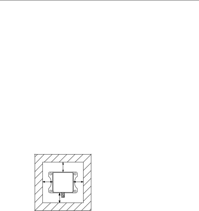
5.3.5Metal-free area
The RF310R can be flush-mounted in metal. Please allow for a possible reduction in the field data values.
|
D |
|
|
6,0$7,& |
|
D |
5) 5 |
D |
|
D |
|
Figure 5-4 Metal-free area for RF310R
To avoid any impact on the field data, the distance a should be ≥ 20 mm.
94 |
SIMATIC RF300 |
System Manual, 09/2007, J31069 D0166-U001-A5-7618 |
Readers 5.3 RF310R with RS422 interface
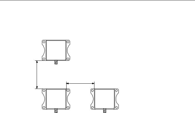
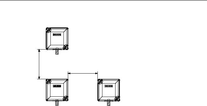
5.3.6Minimum distance between RF310R readers
6,0$7,&
5) 5
0LQLPXP GLVWDQFH EHWZHHQ 5) 5 DQG 5) 5
'' PP
|
' |
6,0$7,& |
6,0$7,& |
5) 5 |
5) 5 |
Figure 5-5 Minimum distance between RF310R readers
SIMATIC RF300 |
95 |
System Manual, 09/2007, J31069 D0166-U001-A5-7618 |

Readers
5.3 RF310R with RS422 interface
5.3.7Technical specifications of the RF310R reader with RS422 interface
Table 5-3 Technical specifications of the RF310R reader with RS422 interface
Inductive interface to the transponder |
|
Transmission frequency for power/data |
13.56 MHz |
Antenna |
Integrated |
Interface to communication module |
RS422 (3964R protocol) |
Baud rate |
19200 baud, 57600 baud, 115200 baud |
Cable length between reader and communication |
Data cable length max. 1000 m |
module |
(shielded cable) |
Read/write distances of reader |
See RF310R field data |
Minimum distance between two RF310R readers |
≥ 400 mm |
Maximum data transfer rate from reader to |
|
transponder (Tag) |
|
Reading |
Approx. 3100 byte/s |
Writing |
Approx. 3100 byte/s |
Functions |
Initialize/read/write transponder |
|
Scan status and diagnostics information |
|
Switch antenna on/off |
|
Repeat command |
|
Scan transponder serial numbers |
Power supply |
24 V DC |
Display elements |
2-color LED (operating voltage, |
|
presence, error) |
Plug connector |
M12 (8-pin) |
Enclosure |
|
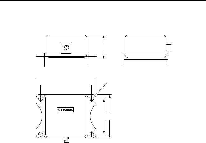
Dimensions (in mm) |
55 x 75 x 30 (without M12 device connector) |
Color |
Anthracite |
Material |
Plastic PA 12 |
Fixing |
4 x M5 screws |
Ambient temperature |
|
during operations |
-25 °C to +70 °C |
during transport and storage |
-40 °C to +85 °C |
Degree of protection to EN 60529 |
IP67 |
Shock to EN 60 721-3-7 Class 7 M2 |
50 g |
Vibration to EN 60 721-3-7 Class 7 M2 |
20 g |
Weight |
Approx. 200 g |
MTBF (Mean Time Between Failures) in years |
169,9 |
Approvals |
Radio to R&TTE guidelines EN 300 330, |
|
EN 301489, CE, FCC, UL/CSA |
Current consumption |
typ. 40 mA |
96 |
SIMATIC RF300 |
System Manual, 09/2007, J31069 D0166-U001-A5-7618 |

Readers 5.3 RF310R with RS422 interface
5.3.8FCC information
Siemens SIMATIC RF310R with RS422 interface FCC ID: NXW-RF310R
This device complies with Part 15 of the FCC rules. Operation is subject to the following two conditions:
(1)This device may not cause harmful interference.
(2)This device must accept any interference received, including interference that may cause undesired operation.
Caution
Any changes or modifications not expressly approved by the party responsible for compliance could void the user's authority to operate the equipment.
5.3.9 |
Ordering data for RF310R with RS422 interface |
|
|
|
|
|
|
|
|
RF310R |
Order No. |
|
|
With RS422 interface (3964R) |
6GT2801-1AA10 |
|
|
IP 67, -25 °C to +70 °C, 55 x 75 x 30 (L x W x H in mm), with integrated |
|
|
|
antenna, max. limit distance 30 mm (depending on transponder) |
|
SIMATIC RF300 |
97 |
System Manual, 09/2007, J31069 D0166-U001-A5-7618 |
Readers
5.3 RF310R with RS422 interface
5.3.10Dimension drawing


6,0$7,& 5) 5


|
|
Figure 5-6 Dimension drawing for RF310R
Dimensions in mm
98 |
SIMATIC RF300 |
System Manual, 09/2007, J31069 D0166-U001-A5-7618 |
Readers
5.4 RF340R
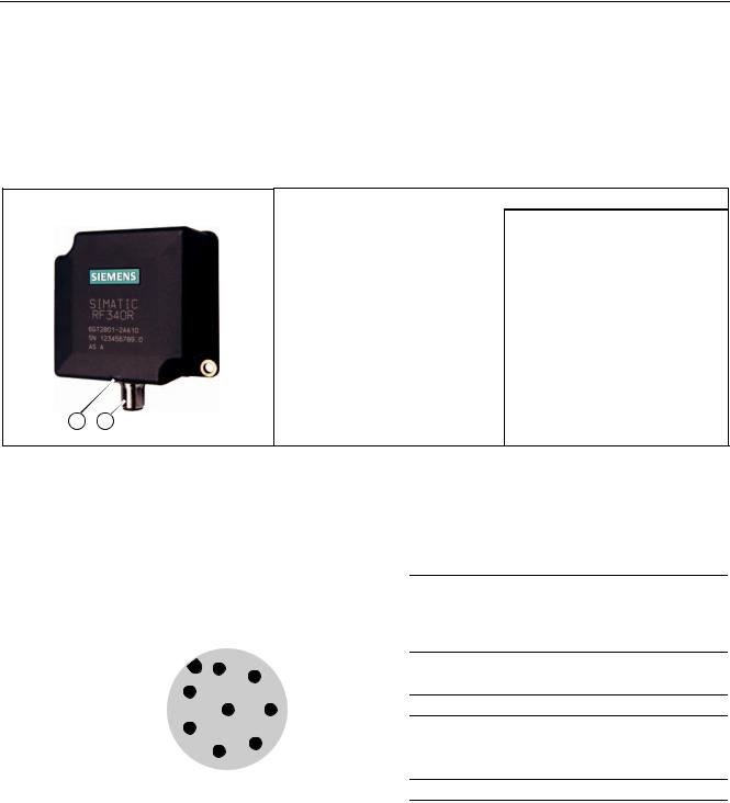
5.4RF340R
5.4.1Features
Reader RF340R |
Features |
|
|
Design |
RS422 interface |
|
|
Status display |
|
Area of application |
Identification tasks on assembly |
|
|
lines in harsh industrial |
|
|
environments |
|
Read/write distance to transponder |
max. 60 mm |
|
Data transmission rate |
• Read: approx. 3,100 byte/s |
|
|
• Write: approx. 3,100 byte/s |
5.4.2Pin assignment of RF340R RS422 interface
Pin |
|
|
|
|
Pin |
Assignment |
|
|
|
|
|
|
|
Device end |
|
|
|
|
|
|
|
8-pin M12 |
|
|
|
|
|
|
|
1 |
+ 24 V |
|
|
|
|
|
|
||
|
|
|
|
|
|
2 |
- Transmit |
|
|
|
|
|
|
|
|
|
|
|
|
|
|
3 |
0 V |
|
|
|
|
|
|
||
|
|
|
|
|
|
4 |
+ Transmit |
|
|
|
|
|
|
||
|
|
|
|
|
|
||
|
|
|
|
|
|
5 |
+ Receive |
|
|
|
|
|
|
6 |
- Receive |
|
|
|
|
|
|
||
|
|
|
|
|
|
7 |
Free |
|
|
|
|
|
|
||
|
|
|
|
|
|
8 |
Earth (shield) |
SIMATIC RF300 |
99 |
System Manual, 09/2007, J31069 D0166-U001-A5-7618 |

Readers
5.4 RF340R
5.4.3Display elements of the RF340R reader
Color |
Meaning |
|
Green |
Flashing |
Operating voltage present, reader not initialized or antenna switched off |
|
Permanentl |
Operating voltage present, reader initialized and antenna switched on |
|
y on |
|
Yellow1) |
Transponder present |
|
Flashing red |
Error has occurred, the type of flashing corresponds to the error code in the |
|
|
|
table in Section "Error codes". The optical error display is only reset if the |
|
|
corresponding reset parameter ("option_1", see FC45 / FB45 documentation, |
|
|
Section "Input parameters") is set. |
1)In the operating state "Without presence", the lighting duration may be very short.
5.4.4Ensuring reliable data exchange
The "center point" of the transponder must be situated within the transmission window.
5.4.5Metal-free area
The RF340R can be flush-mounted in metal. Please allow for a possible reduction in the field data values.
|
D |
|
|
6,0$7,& |
|
D |
|
D |
|
5) 5 |
|
|
D |
|
Figure 5-7 Metal-free area for RF340R
To avoid any impact on the field data, the distance a should be ≥ 20 mm.
100 |
SIMATIC RF300 |
System Manual, 09/2007, J31069 D0166-U001-A5-7618 |
Readers
5.4 RF340R
5.4.6Minimum distance between RF340R readers
5) 5
0LQLPXP GLVWDQFH IURP 5) 5 WR 5) 5
'' PP
'
5) 5 |
5) 5 |
Figure 5-8 Minimum distance between RF340R readers
SIMATIC RF300 |
101 |
System Manual, 09/2007, J31069 D0166-U001-A5-7618 |

Readers
5.4 RF340R
5.4.7Technical data of the RF340R reader
Table 5-4 |
Technical specifications of the RF340R reader |
|
|
|
|
Inductive interface to the transponder |
|
|
Transmission frequency for power/data |
13.56 MHz |
|
Antenna |
|
Integrated |
Interface to communication module |
RS422 (3964R protocol) |
|
Baud rate |
|
19200 baud, 57600 baud, 115200 baud |
Cable length between reader and communication |
Data cable length max. 1000 m |
|
module |
|
(shielded cable) |
Read/write distances of reader |
See RF340R field data |
|
Minimum distance between two RF340R readers |
≥ 500 mm |
|
Maximum data transfer rate |
|
|
reader - transponder (tag) |
|
|
Reading |
|
Approx. 3100 byte/s |
Writing |
|
Approx. 3100 byte/s |
Functions |
|
Initialize/read/write transponder |
|
|
Scan status and diagnostics information |
|
|
Switch antenna on/off |
|
|
Repeat command |
|
|
Scan transponder serial numbers |
Power supply |
24 V DC |
|
Display elements |
2-color LED |
|
|
|
(operating voltage, presence, error) |
Plug connector |
M12 (8-pin) |
|
Enclosure |
|
|
Dimensions (in mm) |
75 x 75 x 40 (without M12 device connector) |
|
Color |
|
Anthracite |
Material |
|
Plastic PA 12 |
Fixing |
|
2 x M5 screws |
Ambient temperature |
|
|
during operations |
-25 °C to +70 °C |
|
during transport and storage |
-40 °C to +85 °C |
|
Degree of protection to EN 60529 |
IP 67 |
|
Shock to EN 60 721-3-7 Class 7 M2 |
50 g |
|
Vibration to EN 60 721-3-7 Class 7 M2 |
20 g |
|
Weight |
|
Approx. 250 g |
MTBF (Mean Time Between Failures) in years |
140,3 |
|
Approvals |
|
Radio to R&TTE guidelines EN 300 330, |
|
|
EN 301489, CE, FCC, UL/CSA |
Current consumption |
typ. 100 mA |
|
102 |
SIMATIC RF300 |
System Manual, 09/2007, J31069 D0166-U001-A5-7618 |
Readers
5.4 RF340R
5.4.8FCC information
Siemens SIMATIC RF340R
FCC ID: NXW-RF340R
This device complies with Part 15 of the FCC rules. Operation is subject to the following two conditions:
(1)This device may not cause harmful interference.
(2)This device must accept any interference received, including interference that may cause undesired operation.
Caution
Any changes or modifications not expressly approved by the party responsible for compliance could void the user's authority to operate the equipment.
5.4.9 |
Ordering data for RF340R |
|
|
|
|
|
|
|
|
Product description |
Order No. |
|
|
Reader RF340R |
6GT2801-2AA10 |
|
|
With RS422 interface (3964R) |
|
|
|
IP67; |
|
|
|
-25 °C to +70 C, dimensions 75 x 91 x 41 (L x W x H in mm); |
|
|
|
with integrated antenna; |
|
|
|
max. limit distance 65 mm (depending on transponder) |
|
SIMATIC RF300 |
103 |
System Manual, 09/2007, J31069 D0166-U001-A5-7618 |

Readers
5.4 RF340R
5.4.10Dimension drawing
|
6,0$7,& |
|
|
|
5) 5 |
Figure 5-9 Dimension drawing for RF340R
Dimensions in mm
104 |
SIMATIC RF300 |
System Manual, 09/2007, J31069 D0166-U001-A5-7618 |
Readers
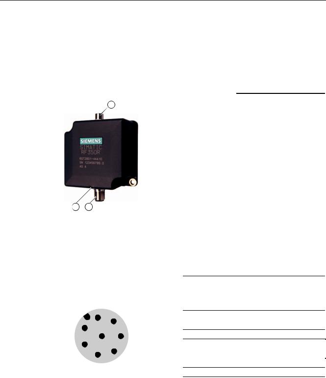
5.5 RF350R
5.5RF350R
5.5.1Features
Reader RF350R |
|
Features |
|
|
|
Design |
Antenna connection |
|
|
|
RS422 interface |
|
|
|
|
|
|
|
Status display |
|
|
Area of application |
Identification tasks in assembly |
|
|
|
lines in harsh industrial |
|
|
|
environments; for external |
|
|
|
antennas |
|
|
|
(ANT 1, ANT 18, ANT 30) |
|
|
Read/write distance to |
Max. 60 mm |
|
|
transponder |
|
|
|
Data transmission rate |
• Read: approx. 3,100 byte/s |
|
|
|
• Write: approx. 3,100 byte/s |
|
|
|
|
|
|
|
|
5.5.2Pin assignment of RF350R RS422 interface
Pin |
|
|
|
|
Pin |
Assignment |
|
|
|
|
|
|
|
Device end |
|
|
|
|
|
|
|
8-pin M12 |
|
|
|
|
|
|
|
1 |
+ 24 V |
|
|
|
|
|
|
||
|
|
|
|
|
|
2 |
- Transmit |
|
|
|
|
|
|
|
|
|
|
|
|
|
|
3 |
0 V |
|
|
|
|
|
|
||
|
|
|
|
|
|
4 |
+ Transmit |
|
|
|
|
|
|
||
|
|
|
|
|
|
||
|
|
|
|
|
|
5 |
+ Receive |
|
|
|
|
|
|
6 |
- Receive |
|
|
|
|
|
|
||
|
|
|
|
|
|
7 |
Free |
|
|
|
|
|
|
||
|
|
|
|
|
|
8 |
Earth (shield) |
SIMATIC RF300 |
105 |
System Manual, 09/2007, J31069 D0166-U001-A5-7618 |

Readers
5.5 RF350R
5.5.3Display elements of the RF350R reader
Color |
Meaning |
|
Green |
Flashing |
Operating voltage present, reader not initialized or antenna switched off |
|
Permanentl |
Operating voltage present, reader initialized and antenna switched on |
|
y on |
|
Yellow1) |
Transponder present |
|
Flashing red |
Error has occurred, the type of flashing corresponds to the error code in the |
|
|
|
table in Section "Error codes". The optical error display is only reset if the |
|
|
corresponding reset parameter ("option_1", see FC45 / FB45 documentation, |
|
|
Section "Input parameters") is set. |
1)In the operating state "Without presence", the lighting duration may be very short.
5.5.4Ensuring reliable data exchange
The "center point" of the transponder must be situated within the transmission window.
5.5.5Metal-free area
The RF350R reader does not have an internal antenna. Operation is not affected by mounting on metal or flush-mounting in metal. For information about the metal-free area required by the external antennas, refer to the corresponding section of the chapter Antennas (Page 110).
106 |
SIMATIC RF300 |
System Manual, 09/2007, J31069 D0166-U001-A5-7618 |

Readers
5.5 RF350R
5.5.6Technical data of the RF350R reader
Table 5-5 |
Technical specifications of the RF350R reader |
|
|
|
|
Inductive interface to the transponder |
|
|
Transmission frequency for power/data |
13.56 MHz |
|
Antenna |
|
External, plug-in MOBY E antennas ANT 1, |
|
|
ANT 18 or ANT 30 |
Interface to communication module |
RS422 (3964R protocol) |
|
Baud rate |
|
19200 baud, 57600 baud, 115 baud |
Cable length between reader and communication |
Data cable length max. 1000 m |
|
module |
|
(shielded cable) |
Read/write distances of reader |
See field data |
|
Minimum distance between two antennas |
See field data |
|
Maximum data transfer rate |
|
|
reader - transponder (tag) |
|
|
Reading |
|
Approx. 3100 byte/s |
Writing |
|
Approx. 3100 byte/s |
Functions |
|
Initialize/read/write transponder |
|
|
Scan status and diagnostics information |
|
|
Switch antenna on/off |
|
|
Repeat command |
|
|
Scan transponder serial numbers |
Power supply |
24 V DC |
|
Display elements |
2-color LED |
|
|
|
(operating voltage, presence, error) |
Plug connector |
M12 (8-pin); M8 (4-pin) for antenna |
|
Enclosure |
|
|
Dimensions (in mm) |
75 x 75 x 40 (without M12 device connector) |
|
Color |
|
Anthracite |
Material |
|
Plastic PA 12 |
Fixing |
|
2 x M5 screws |
Ambient temperature |
|
|
during operations |
-25 °C to +70 °C |
|
during transport and storage |
-40 °C to +85 °C |
|
Degree of protection to EN 60529 |
IP65 |
|
Shock to EN 60 721-3-7 Class 7 M2 |
50 g |
|
Vibration to EN 60 721-3-7 Class 7 M2 |
20 g |
|
Weight |
|
Approx. 400 g |
MTBF (Mean Time Between Failures) in years |
109 |
|
Approvals |
|
Radio to R&TTE guidelines EN 300 330, |
|
|
EN 301489, CE, FCC, UL/CSA |
Current consumption |
typ. 100 mA |
|
SIMATIC RF300 |
107 |
System Manual, 09/2007, J31069 D0166-U001-A5-7618 |

Readers
5.5 RF350R
5.5.7FCC information
Siemens SIMATIC RF350R
FCC ID: NXW-RF350R
This device complies with Part 15 of the FCC rules. Operation is subject to the following two conditions:
(1)This device may not cause harmful interference.
(2)This device must accept any interference received, including interference that may cause undesired operation.
Caution
Any changes or modifications not expressly approved by the party responsible for compliance could void the user's authority to operate the equipment.
5.5.8 |
Ordering data for RF350R |
|
|
|
|
|
|
|
|
Product description |
Order No. |
|
|
Reader RF350R |
6GT2801-4AA10 |
|
|
With RS422 interface (3964R) |
|
|
|
IP 65; |
|
|
|
-25 °C to +70 °C, dimensions 75 x 96 x 41 (L x W x H in mm); |
|
|
|
for plug-in antennas from the MOBY E product range; |
|
|
|
max. limit distance 65 mm (depending on transponder) |
|
108 |
SIMATIC RF300 |
System Manual, 09/2007, J31069 D0166-U001-A5-7618 |
Readers
5.5 RF350R
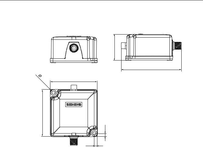
5.5.9Dimension drawing
6,0$7,& 5) 5
Figure 5-10 RF350R dimension drawing
Dimensions in mm
SIMATIC RF300 |
109 |
System Manual, 09/2007, J31069 D0166-U001-A5-7618 |
Readers
5.5 RF350R
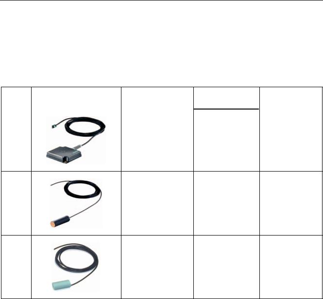
5.5.10Antennas
5.5.10.1Features
You can use the following plug-in antennas from the MOBY E product spectrum for the RF350R reader:
Antenna Product photo |
Limit distance Sg |
Dimensions |
Suitable for dynamic |
|
in mm 1) |
(L x B x H) |
operation |
|
|
in mm |
|
MOBY E |
to 60 |
75 x 75 x 20 |
Yes |
ANT 1 |
|
|
|
MOBY E |
to 13 |
Ø M18 x 50 |
no |
ANT 18 |
|
|
|
MOBY E |
to 22 |
Ø M30 x 58 |
no |
ANT 30 |
|
|
|
1) depending on the transponder used
ANT 1
The ANT 1 is an antenna in the mid performance range and can be used to the customer's advantage in production and assembly lines due to its manageable housing shape. The antenna dimensions make it possible to read/write large quantities of data dynamically from/to the tag during operation. The antenna cable can be connected at the reader end.
ANT 18
The ANT 18 is designed for use in small assembly lines. Due to its small, compact construction, the antenna can be easily positioned for any application using two plastic nuts (included in the package). The antenna cable can be connected at the reader end. With the RF320T and RF340T tags, communication with the data storage unit is only possible in static mode.
110 |
SIMATIC RF300 |
System Manual, 09/2007, J31069 D0166-U001-A5-7618 |
Loading...