


PXC3.E16A100A
Siemens PXC3.E16A100A, PXC3.E72-100A, PXC3.E72A100A, PXC3.E75-100A, PXC3.E75A100A Datasheet
...
CM1N9203en_05
2015
-11-23
Building Technologies
s
9
203
9203mmP01
Desigo™ TRA
Room automation stations
PXC3.E...
• Modular, programmable room automation stations for HVAC, lighting, and
shading.
• BACnet / IP communications; BACnet profile ASC (BTL label).
• Optional island bus to connect TX-I/O modules with any data point mix
(including bus supply).
• Optional KNX PL-Link peripheral bus to connect sensors, actors and room
units (including bus supply).
• Optional DALI bus to connect ballasts (including bus supply).
• Optional Connection of individual devices with KNX S-Mode via
KNX PL-Link.
• Ethernet switch for communication and tool connection.
• USB Device interface.
• Operating voltage AC 24 V.
• Mounting on standard mounting rail.

2 / 12
Siemens PXC3.E... Room automation stations CM1N9203en_05
Building Technologies 2015-11-23
Use
Starting with Desigo V5, PXC3 series room automation stations with Total Room
Automation applications (TRA) can be used for buildings with more sophisticated
requirements on functionality and flexibility. TRA is used when several disciplines
(HVAC, lighting, shading) are combined to form one total solution and when total
flexibility is required. TRA is perfect for solutions optimizing energy (class A)
without loss of comfort.
Functions
A PXC3 series room automation station can assume control for multiple rooms.
These programmable room automation stations provide the infrastructure to
provide and process system- and application-specific functions.
Desigo
version
Product No.
Stock No.
Function Number of I/O
data points
KNX PLLink
TX-I/O modules DALI bus
V6
PXC3.E16A-
100A
S55376-C118
DALI applications
only
64 3) - - - -
max. 64
ballasts
4)
PXC3.E72-100A
S55376-C130
typically 4 rooms
typically 8 room
segments 1)
140 3)
max. 64
devices
max. 72 physical
I/O points
- -
PXC3.E72A-
100A
S55376-C131
typically 4 rooms
typically 8 room
segments
1)
140 3)
max. 64
devices
max. 72 physical
I/O points
max. 64
ballasts
4)
PXC3.E75-100A
S55376-C132
typically 8 rooms
typically 16 room
segments 1)
280 3)
max. 64
devices
max. 200 physical
I/O points
- -
PXC3.E75A-
100A
S55376-C133
typically 8 rooms
typically 16 room
segments
1)
280 3)
max. 64
devices
max. 200 physical
I/O points
max. 64
ballasts
4)
V5.1
V5.1SP
2)
PXC3.E72
S55376-C100
typically 4 rooms
typically 8 room
segments 2)
140 3)
max. 64
devices
max. 72 physical
I/O points
- -
PXC3.E72A
S55376-C101
typically 4 rooms
typically 8 room
segments 2)
140 3)
max. 64
devices
max. 72 physical
I/O points
max. 64
ballasts 4)
PXC3.E75
S55376-C102
typically 8 rooms
typically 16 room
segments
2)
280 3)
max. 64
devices
max. 200 physical
I/O points
- -
PXC3.E75A
S55376-C103
typically 8 rooms
typically 16 room
segments 2)
280 3)
max. 64
devices
max. 200 physical
I/O points
max. 64
ballasts 4)
1)
Architectural building grid (also called room axis).
2)
If V6 applications are loaded into a V5.1 device, less rooms are supported,
because V6 applications require more memory space.
To find out, DCM features the Load calculation tool.
3)
Total number of data point used by TX-I/O, KNX PL-Link and DALI.
For details see Desigo Technical principles CM110664, chapter 18.
4)
Commercially available DALI -ballasts with a DALI address.
Control of several
rooms
Variants

3 / 12
Siemens PXC3.E... Room automation stations CM1N9203en_05
Building Technologies 2015-11-23
• The room automation stations have a 2-port Ethernet switch to support for lowcost cabling via line topology.
• A USB Device port is available for service and commissioning.
• TX-I/O modules connected directly to the PXC3 allow for direct connection of
field devices. This offers maximum flexibility.
• The KNX PL-Link peripheral bus supports room operator units, sensors, and
actuating devices. Selected Siemens field devices to the KNX PL-Link bus
(devices with the KNX PL-Link logo) can be connected.
The KNX PL-Link bus supports integration of commercially available devices
with KNX S-Mode (requires ETS engineering).
• The DALI bus supports lighting control. Commercially available DALI EBGs
(electronic ballasts) can be connected.
Equipment combinations
Depending on the type, PXC3 series room automation stations can be operated
with TX-I/O devices and devices with KNX PL-Link.
DALI device type
Description
Supported
0
Fluorescent Lamps
Yes
7
Switching Function
Yes 1 Self-contained Emergency Lighting
Yes **)
3
Low Voltage Halogen Lamps
Partly *)
5
Conversion digital into D.C. Voltage
Partly *)
4
Incandescent Lamps
No
2
HID Discharge Lamps
No
6
LED Modules
Yes **)
8
Colour Control
No
9
Sequencer
No
10
Optical Control
No
*) Partly supported means that basic functions are supported like with type 0, but
no further type specific functions.
**) In Desigo V6 and later
Communications
TX-I/O, KNX PL-Link
DALI
4 / 12
Siemens PXC3.E... Room automation stations CM1N9203en_05
Building Technologies 2015-11-23
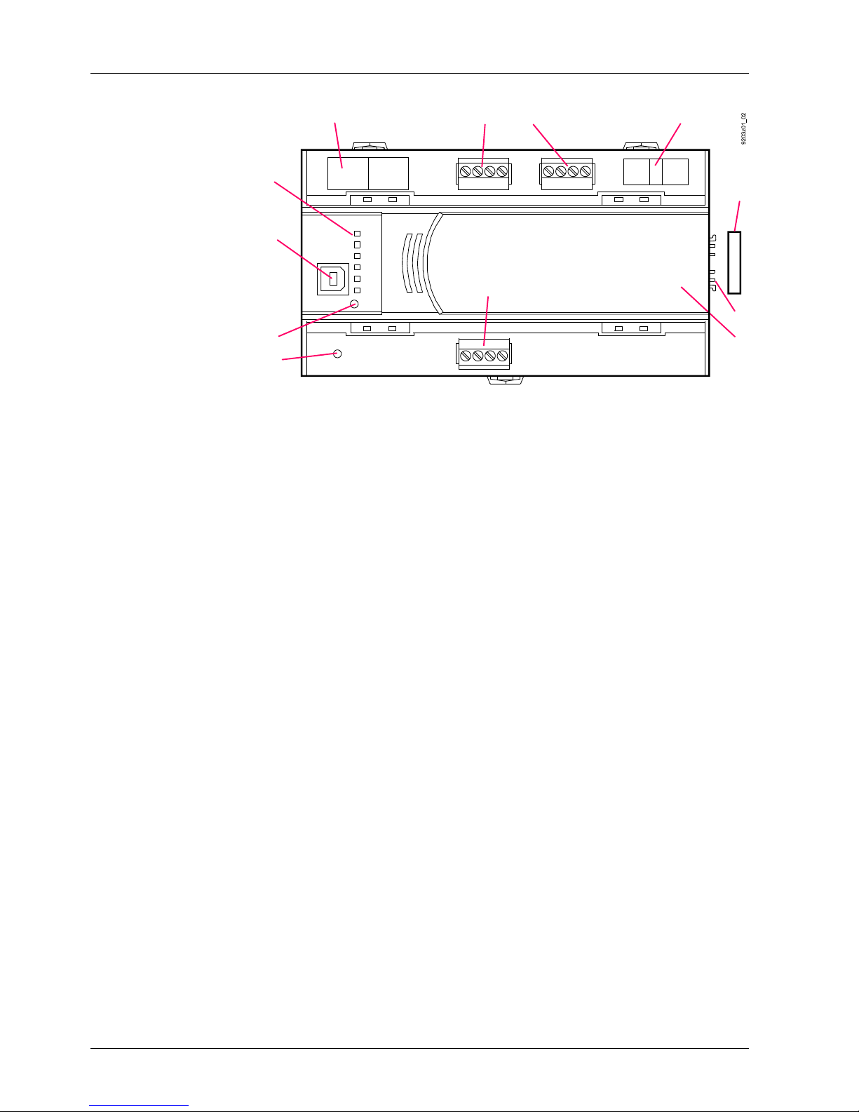
Mechanical design
The compact build allows for mounting the devices on a standard mounting rail.
1
2
3
45
6
8
9
7
11
12 12
10
13
12
1
Plastic housing
2
Island bus plug connection
3
T 10 A fuse for AC 24 V peripheral supply via island bus
4
Plug-in terminal block (operating voltage)
5
Plug-in terminal block KNX PL-Link
6
2-port Ethernet switch (with 2 LEDs per port for display purposes)
7
DALI bus
8
LED display for device and system status
9
USB Device interface
10
Service pin
11
Service pin DALI
12
Slider for mounting on DIN rail
13
Island bus cover (supplied with the device)
The bus supplies for island bus, KNX PL-Link and DALI are integrated in the room
automation station.
For better reliability of the room automation station, the bus supplies and the
AC 24 V outlets are independent from the room automations station's own supply.
V6: The bus supplies are switched on by default and can be swiched off via tool if
not needed.
V5.1: The bus supplies are switched off automatically as long as no device is
connected to the respective bus during engineering.
V5.1 devices do NOT support the V6 functionality of field bus supply management.
The internal KNX PL-Link supply must not be operated in parallel with an
external supply. It must be switched off via tool when using an external supply.
This is typically the case if the devices connected to the KNX PL-Link consume
more than the 160 mA available from the internal supply.
Power supply
KNX PL-Link supply
 Loading...