


 Loading...
SAMMS-MV™
Siemens Advanced Motor Master System for Medium Voltage Motors
User's Manual
1 2 3 4 5 6 7 8 9 10 11 12 13 14 15 16
Manual No. MVC-9108
IMPORTANT
The information contained herein is general in nature and not intended for specific application purposes. It does not relieve the user of responsibility to use sound practices in application, installation, operation, and maintenance of the equipment purchased. Siemens reserves the right to make changes in the specifications shown herein or to make improvements at any time without notice or obligations. Should a conflict arise between the general information contained in this publication and the contents of drawings or supplementary material or both, the latter shall take precedence.
QUALIFIED PERSON
For the purpose of this manual a qualified person is one who is familiar with the installation, construction or operation of the equipment and the hazards involved. In addition, he has the following qualifications:
(a)is trained and authorized to de-energize, clear, ground, and tag circuits and equipment in accordance with established safety practices.
(b)is trained in the proper care and use of protective equipment such as rubber gloves, hard hat, safety glasses or face shields, flash clothing, etc., in accordance with established safety practices.
(c)is trained in rendering first aid.
SUMMARY
These instructions do not purport to cover all details or variations in equipment, nor to provide for every possible contingency to be met in connection with installation, operation, or maintenance. Should further information be desired or should particular problems arise which are not covered sufficiently for the purchaser’s purposes, the matter should be referred to the local sales office.
The contents of this instruction manual shall not become part of or modify any prior or existing agreement, commitment or relationship. The sales contract contains the entire obligation of Siemens Energy & Automation, Inc. The warranty contained in the contract between the parties is the sole warranty of Siemens Energy & Automation, Inc. Any statements contained herein do not create new warranties or modify the existing warranty.

Contents
1 |
Introduction ............................................. |
2 |
|
1.1 |
About this Manual ............................................ |
3 |
|
1.2 About the SAMMS-MV Device.......................... |
3 |
||
|
1.2.1 The SAMMS-MV Device Models ............ |
4 |
|
|
1.2.2 |
Advanced Protection for Medium-Voltage |
|
|
|
Motors ................................................... |
4 |
|
1.2.3 |
Overload Protection ............................... |
5 |
|
1.2.4 |
Programming Control Circuits ................ |
5 |
|
1.2.5 Using the Standardized Control Panel .... |
5 |
|
2 |
Installing the SAMMS-MV Device .......... |
7 |
|
2.1Receiving and Storing the SAMMS-MV Device . 7
2.2 |
Where to Locate the Device ............................. |
7 |
|
2.3 |
Mounting the Device......................................... |
7 |
|
2.4 |
Connecting the Device ..................................... |
7 |
|
|
2.4.1 |
Wiring Guidelines ................................... |
7 |
|
2.4.2 |
Grounding the Device ............................ |
9 |
|
2.4.3 |
Connecting the Device to a Control Power |
|
|
|
Source ................................................... |
9 |
|
2.4.4 |
Connecting Input and Output Devices to |
|
|
|
the SAMMS-MV Device ......................... |
9 |
|
2.4.5 |
Communications Connection ................. |
9 |
3 |
Operating the SAMMS-MV Device ...... |
11 |
3.1 |
Password Protection....................................... |
11 |
3.2 |
Using the Reset/Test Push Button .................. |
11 |
|
3.2.1 Performing a Lamp Test ....................... |
11 |
|
3.2.2 Performing an Overload Relay Test ...... |
11 |
3.3 |
Motor Control ................................................. |
11 |
3.4 |
Output Devices............................................... |
12 |
3.5 |
Input Devices.................................................. |
12 |
3.6 |
Ladder Diagrams ............................................ |
13 |
|
3.6.1 Library of Standard Ladder Diagrams ... |
13 |
|
3.6.2 Custom Ladder Diagrams .................... |
13 |
3.7 |
Incomplete Sequence..................................... |
17 |
3.8 |
Intelligent Reduced-Voltage |
|
|
Starting (SAMMS-MVX Only)........................... |
17 |
3.9Ridethrough Upon Loss of Power
|
(SAMMS-MVX Only)........................................ |
17 |
3.10 |
Overload Protection ........................................ |
17 |
3.11 |
Motor Ambient Temperature ........................... |
17 |
3.12 |
Protection Curves and Overload |
|
|
Classes .......................................................... |
19 |
3.13 |
Ultimate Trip Level and Service Factor ............ |
23 |
3.14 |
Phase Unbalance ........................................... |
23 |
3.15 |
Dual Overload Protection ................................ |
23 |
3.16 |
Jam Protection (SAMMS-MVX Only) ............... |
23 |
3.17 |
Loss of Load Protection/Warning |
|
|
(SAMMS-MVX Only)........................................ |
23 |
3.18 |
Process Current Warning (SAMMS-MVX Only) 23 |
|
3.19 |
Stator Protection............................................. |
23 |
3.20 |
Rotor Protection ............................................. |
23 |
3.21 |
Repetitive Starts ............................................. |
24 |
3.22 |
Start Inhibit ..................................................... |
24 |
3.23 |
Cooling Time Constants ................................. |
24 |
3.24 |
Normalized Temperature Rise for Class B and |
|
|
Class F Insulation ........................................... |
24 |
3.25 |
Ground Fault Detection .................................. |
24 |
3.26 |
Autoreset After a Trip (SAMMS-MVX Only) ...... |
26 |
3.27 |
Emergency Restarting .................................... |
26 |
3.28 |
Using the Hand Held Communicator (HHC) ... |
26 |
|
3.28.1The (F)unction Key ............................... |
26 |
|
3.28.2The LIST Key ....................................... |
26 |
|
3.28.3UP and DOWN Keys ............................ |
28 |
|
3.28.4Using the ENTER Key .......................... |
28 |
3.29 |
Using the SAMMS-MV Device |
|
|
Functions ....................................................... |
28 |
|
3.29.1Program Mode/Passwords ................... |
32 |
|
3.29.2 SAMMS-MV Functions ........................ |
32 |
4 |
Troubleshooting the SAMMS-MV |
|
|
Device ..................................................... |
40 |
Appendix A - Technical Specifications of the |
||
|
SAMMS-MV Device ............................... |
43 |
©Copyright 1994 Siemens Energy & Automation, Inc.
ACCESS, SAMMS, SAMMS-MV, Series 81000, SEAbus, Power Monitor, Power Monitor PC, WinPM, and SIEServe are trademarks of Siemens Energy & Automation, Inc. Microsoft is a registered trademark and Windows is a trademark of Microsoft Corporation. IBM is a registered trademark of International Business Machines, Inc.
1
1 Introduction
1 Introduction
The SAMMS-MV electronic motor control and protection device is designed and manufactured in accordance with the latest applicable provisions of the National Electric Code, Underwriters Laboratories Standards and Procedures, NEMA Standards, and the National Electric Safety Code. You must thoroughly read and understand this user’s manual before you begin any work with the SAMMS-MV device. Successful application and operation of this equipment depends as much upon proper installation and maintenance by the user as it does upon the careful design and fabrication by Siemens.
The purpose of this instruction manual is to assist the user in developing safe and efficient procedures for the installation, maintenance, and use of the equipment.
Contact the nearest Siemens representative if any additional information is desired.
Qualified Person
For the purpose of this manual and product labels, a“Qualified Person” is one who is familiar with the installation, construction and operation of this equipment, and the hazards involved. In addition, this person has the following qualifications;
•Training and authorization to energize, de-energize, clear, ground, and tag circuits and equipment in accordance with established safety practices.
•Training in the proper care and use of protective equipment such as rubber gloves, hard hat, safety glasses, face shields, flash clothing, etc., in accordance with established safety procedures.
•Training in rendering first aid.
Signal Words
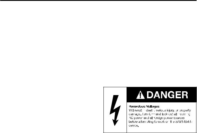
The signal words “Danger”, “Warning”, and “Caution” used in this manual indicate the degree of hazard that may be encountered by the user. These words are defined as:
Danger—Indicates an imminently hazardous situation which, if not avoided, will result in death or serious injury. Warning—Indicates an potentially hazardous situation which, if not avoided, could result in death or serious injury. Caution—Indicates an potentially hazardous situation which, if not avoided, may result in minor or moderate injury.
Dangerous Procedures
In addition to other procedures described in this manual as dangerous, user personnel must adhere to the following:
1.Always work on de-energized equipment. Always de-ener- gize a breaker, or contactor, and remove it from the equipment before performing any tests, maintenance, or repair.
2.Always perform maintenance on equipment employing springs after the spring-charged mechanisims are discharged.
3.Always let an interlock device or safety mechanism perform its function without forcing or defeating the device.
Field Service Operation
Siemens can provide compentent, well-trained Field Service Representatives to provide technical guidance and advisory assistance for the installation, overhaul, repair, and maintenance of Siemens equipment, processes, and systems. Contact regional service centers, sales offices, or the factory for details.
2

1 Introduction
1.1 About this Manual
This manual introduces you to the Siemens Advanced Motor Master System (SAMMS-MVä) motor protection and control relay which incorporates protection designed for medium voltage machines. This manual also contains information for installing and operating the device, communicating with other devices over the ACCESSä electrical distribution communications system, and troubleshooting the device. This manual also provides a helpful technical reference for you to use. Refer to table 1.1 to determine which section of the manual contains the information that you need.
These instructions prepare you to handle, install, operate and maintain the SAMMS-MV device and the Hand-Held Communicator (HHC). The individual starters and controllers used are designed for specific applications based upon your equipment and needs. Instructions covering these starters and components are not included in this manual. For this information, refer to instructions and drawings furnished with your equipment, or contact your Siemens representative. You must read these instructions and determine applicability of your equipment. Refer to the nameplate data on your controller and to the electrical diagrams supplied with your controller to determine applicability of your equipment.
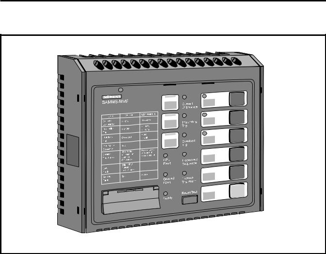
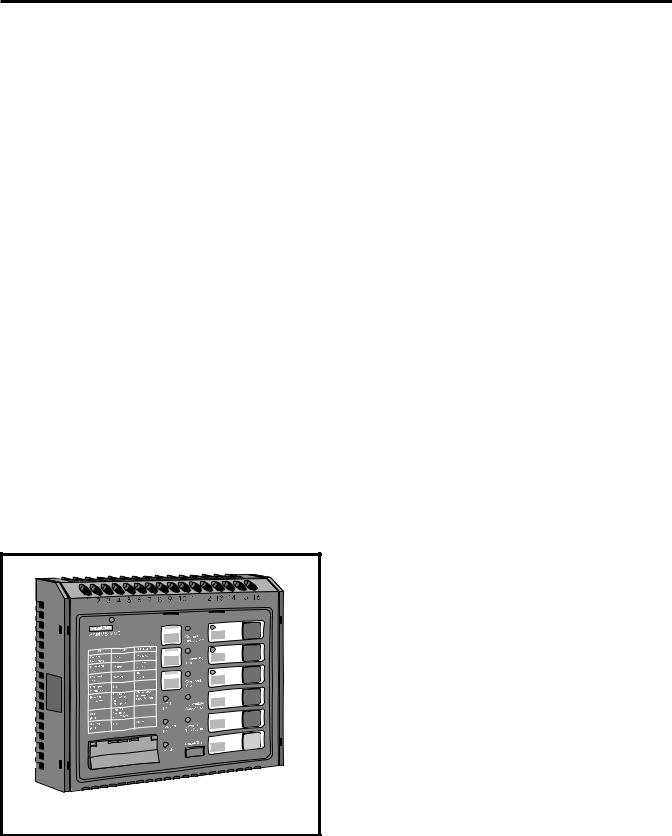
1.2 About the SAMMS-MV Device
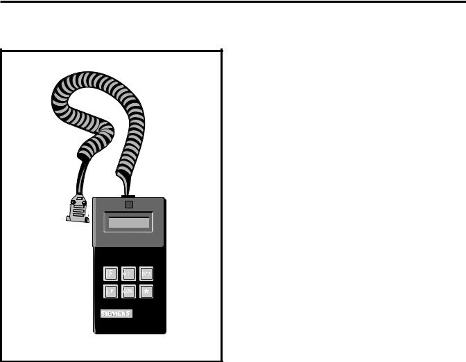
The SAMMS-MV device, shown in Figure 1.1, is a softwareconfigured electronic motor control and overload protection device that incorporates protection tailored to the special characteristics of medium voltage motors. The SAMMS-MV system includes a microprocessor-based SAMMS-MV device which receives signal inputs from a set of current transformers (either 3-1Ø or 1-3Ø) and power input from a 12 volt tap on the controller’s control power transformer. To perform certain monitoring and setup activities, a Hand-Held Communicator (HHC) shown in Figure 1.2, is required. The SAMMS-MV device is a multi-functional device offering the following:
•advanced motor protection for medium voltage motors
•pre-programmed control circuits
•standardized control panel with input/output devices replacing conventional push-buttons, pilot lights and selector switches
•diagnostics
•statistical motor data
•real-time metering
•local display of all motor and control circuit data
•open architecture communications using the ACCESS system
Note: The SAMMS-MV device does not replace the disconnect device (drawout contactor mounting or isolating switch) or the contactor itself.
If you need to... |
...refer to this section |
|
|
learn about the SAMMS-MV device |
Section 1, Introduction |
|
|
install the SAMMS-MV device |
Section 2, Installing the SAMMS-MV Device |
|
|
operate the SAMMS-MV device |
Section 3, Operating the SAMMS-MV Device |
|
|
operate the Hand-Held Communicator |
Section 3, Operating the SAMMS-MV Device |
|
|
connect the SAMMS-MV device to the ACCESS |
Section 2, Installing the SAMMS-MV Device |
System |
|
|
|
troubleshoot the SAMMS-MV device |
Section 4, Troubleshooting the SAMMS-MV Device |
|
|
learn about the technical specifications of the |
Appendix A, Technical Specifications of the SAMMS-MV Device |
SAMMS-MV device |
|
|
|
Table 1.1 Where to find information |
|
3
1 Introduction
1 2 3 4 5 6 7 8 9 10 11 12 13 14 15 16
Figure 1.1 SAMMS-MV, front view
1.2.1 The SAMMS-MV Device Models
The SAMMS-MV device is available in two models: SAMMS-MVE and SAMMS-MVX. Each model meets the various demands of industrial and commercial specifications and installations. Table 1.2 compares the features of each model.
The SAMMS-MV device is designed for critical process control where prevention of downtime is critical. It offers motor control and protection along with motor diagnostic and motor/driven equipment protection. Engineering and operating personnel have access to important data enabling them to optimize motor-driven equipment capabilities, maximize the process system output and facilitate maintenance.
SAMMS-MVX is a full function model, applicable to all control needs, from a simple across-the-line unit to a more complicated reduced voltage scheme. It includes all of the functions listed in table 3.7. Any of the standard control circuits listed in table 3.3, or a custom circuit, may be downloaded. The SAMMS-MVX device accepts up to four remote inputs, while SAMMS-MVE accepts two remote inputs.
SAMMS-MVE is a model of SAMMS-MV tailored to across-the- line (FVNR) applications. It provides all of the protective functions of the SAMMS-MVX device, except that it has no jam
protection (F23), loss of load protection/alarm (F24), or process current warning (F22) functions. Functions F3 and F5 associated with two-speed applications are not available. No provision for automatic reset (F8) is provided. SAMMS-MVE accepts one remote input, and provides one output to actuate a single contactor. An alarm contact is not available with SAMMS-MVE.
These remote inputs are compatible with all PLCs and electromechanical remote control devices that have a 120VAC or 125VDC input signal.
1.2.2 Advanced Protection for Medium-Voltage Motors
For advanced protection of medium voltage motors, the SAMMS-MV device uses a motor model algorithm that continually calculates the stator winding and housing temperature as well as the rotor temperature as a function of the motor rms current. The motor model compares the calculated temperature to trip temperature values and provides a signal that trips the motor off line when the motor reaches a trip temperature value. The model closely emulates the heating and cooling of the motor windings as well as the rotor and provides protection against both transient and steady-state overload conditions.
4
1 Introduction
Figure 1.2 Hand-Held Communicator (HHC)
1.2.3 Overload Protection
The motor model offers the selection of overload classes 2 through 23.
The SAMMS-MV device offers more accurate motor protection than traditional thermal overload and most electronic motor protection devices. This prolongs motor life by eliminating nuisance tripping for multiple restarts, and allowing for proper cool down time when the motor winding temperature or rotor temperature reaches a critically high value.
1.2.4 Programming Control Circuits
The SAMMS-MV device allows you to modify its configuration by programming the microprocessor. The SAMMS-MV device replaces conventional timers, overload relays, pushbuttons, and selector switches.
SAMMS-MVE is preloaded with seven across-the-line control circuits, and the desired control circuit can be selected using the Hand-Held Communicator (HHC.) Alternatively, a custom across-the-line circuit may be downloaded from a PC.
A library of more than 40 typical control circuits exists for use with SAMMS-MVX to meet applications ranging from simple
across-the-line starters to complicated reduced-voltage starters. With optional software, the specified control circuit can be loaded either from the library or from a modified version into the microprocessor’s memory, in the factory or on site, using an IBM®-PC compatible computer. If you would like to learn more about this software package, refer to SAMMS Custom Software Manual, Bulletin CP 3291.
Highly specialized control circuits can be developed and existing circuits can be modified using an optional IBM-PC compatible software package. This software uses conventional engineering symbols along with pull-down menus and a mouse to draw ladder diagrams. When you have finished drawing the diagram, the software translates the diagram into microprocessor machine code and downloads it into the SAMMS-MV device’s memory.
1.2.5 Using the Standardized Control Panel
The SAMMS-MV device can be used for local and/or remote control. The SAMMS-MVE device provides two light bars, while the SAMMS-MVX model provides three light bars. Each model includes six pushbuttons with lights and tactile feedback. You can program these light bars and pushbuttons for the various functions of the control circuit used.
The test/reset button is used to test and reset the overload function and to test the front panel lights.
Diagnostics
Eight diagnostic LEDs, located on the front panel, provide information about conditions affecting the motor.
Statistical Data about the Motor
The microprocessor’s memory stores statistical data about the motor and displays this data on the Hand-Held Communicator (HHC).
Real-Time Metering Data
The Hand-Held Communicator displays real-time metering data.
Local Displaying of Motor and Circuit Data
The HHC and the eight (8) diagnostic LEDs display motor and control circuit data. The eight (8) diagnostic LEDs are located on the front panel of the device.
Communicating with Other Devices
The SAMMS-MV device communicates with other devices via the ACCESS system. When connected to the ACCESS system, the SAMMS-MV device provides two-way communication with the Power Monitor™ display and monitoring unit, an IBM PCcompatible computer running the Power Monitor PC™ communications and supervisory software or another supervisory device. This ability allows you to control and monitor motors from a centralized location. You can have remote access to all SAMMS-MV data such as diagnostics, statistical data, realtime metering, and controller status. If you would like to learn more about the ACCESS system, refer to Installing the ACCESS System (manual no. SG6028).
5

1 Introduction
SAMMS-MV Model |
SAMMS-MVE |
SAMMS-MVX |
|
|
|
Application |
|
|
Across-the-line (FVNR) |
X |
X |
Reversing |
|
X |
Two-speed |
|
X |
Reduced voltage |
|
X |
|
|
|
Functions available (see table 3.7) |
F0-F21 plus F25-F27 (except no |
F0-F27 |
|
F3, F5, or F8) |
|
|
|
|
Ridethrough upon loss of power |
No |
Yes |
|
|
|
Ground fault protection/alarm |
Yes |
Yes |
|
|
|
Programmable alarm contact |
No |
Yes |
|
|
|
Control circuits |
Seven (preloaded), selectable with |
Any downloadable control circuit |
|
HHC. May download any custom |
|
|
across-the-line control circuit |
|
|
|
|
Change settings requires password |
Yes |
Yes |
|
|
|
Remote inputs |
One |
Four |
|
|
|
Outputs |
One |
Three |
|
|
|
Light bars |
Two |
Three |
|
|
|
Table 1.2 SAMMS-MV models
6
2 Installing the SAMMS-MV Device
2 Installing the SAMMS-MV Device
This section provides instructions for installing the SAMMS-MV device. You should adapt these instructions to suit the needs of your installation and equipment.
2.1 Receiving and Storing the
SAMMS-MV Device
Thoroughly inspect the equipment before accepting the shipment from the transportation company. Compare each item received against the packing list and report any shortages or damaged equipment to the carrier.
If you are not going to install the SAMMS-MV device immediately, store it in a clean, dry location at ambient temperatures from -40° C to 85° C. The surrounding air should not contain any corrosive fumes or electrically conductive contaminants. The storage location should prevent condensation from forming within the equipment enclosure.
Note: Improper storage can cause equipment damage. Follow all storage instructions carefully. Failure to follow storage instructions will void the warranty.
2.2 Where to Locate the Device
You can locate the SAMMS-MV device and its associated devices in most industrial equipment environments. Unless the device is designed for specific requirements, you should install the SAMMS-MV device and its controller in an area where the following conditions exist:
•Ambient air must be free of dirt, combustible vapor, steam, electrically conductive or corrosive material.
•Area around the controller must provide access to the equipment for inspection, maintenance and operation.
2.3 Mounting the Device
The SAMMS-MV device mounts in a front door panel of the low voltage compartment of Siemens Series 81000™ medium voltage control (MVC) equipment. Mount the device in the normal low-voltage compartment associated with each medium voltage controller.
2.4 Connecting the Device
This section contains general guidelines that you should follow to connect the SAMMS-MV device. These guidelines include instructions for routing the wire, connecting the wire and grounding the device. Use these guidelines to install the SAMMS-MV device and its peripheral devices in a motor controller. Also use these guidelines to connect the motor controller to the motor.
When Siemens supplies a SAMMS-MV device as part of a motor controller, Siemens personnel install the wiring between the SAMMS-MV device and its peripheral devices in the motor
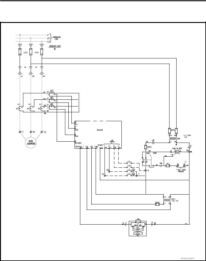
controller at the factory. The schematic diagram used contains three components: a connection diagram, a ladder diagram and a wiring diagram. The connection diagram illustrates the connections between the SAMMS-MV device and its peripheral devices. The ladder diagram illustrates the control circuit loaded into the SAMMS-MV device. Figure 2-1 shows a typical connection diagram for the SAMMS-MV device.
If Siemens does not supply the motor controller, the retrofitter or original equipment manufacturer should develop an equivalent electrical scheme.
2.4.1 Wiring Guidelines
You must observe the following guidelines when installing the SAMMS-MV device and connecting it with its peripheral devices.
Note: Failure to follow these guidelines can cause pickup of unwanted signals resulting in erratic operation and damage to the SAMMS-MV device.
Guideline 1: Separate the low-voltage (115 VAC or less) from the higher voltage conductors (460 VAC or higher) as much as possible. If low-voltage and medium-voltage wires must cross paths, make sure that they intersect at a right angle.
Guideline 2: To eliminate noise coupling, install all twisted pairs or wrap wires in such a way that a complete twist or wrap occurs at least every two inches.
Guideline 3: Place the low-voltage leads near the controller chassis.
Guideline 4: Use at least AWG 14 stranded copper wire for any low-voltage control wiring that you route outside the motor controller enclosure. Connections to the SAMMS-MV unit must be made with wire no larger than AWG 14.
Guideline 5: To avoid ground loops, ground each motor controller at a single ground point.
The top portion of the device contains 16 terminal locations for connecting control power leads, power supply, ground, inputs and outputs. (Refer to Figure 2.2 for a description of each terminal block assignment.)
7
2 Installing the SAMMS-MV Device
Figure 2.1 Full voltage non-reversing connection diagram
8
2 Installing the SAMMS-MV Device
2.4.2 Grounding the Device
As stated in Guideline 5, ground each motor controller at a single ground point. The grounding path to earth must be permanent and continuous. It must also be able to safely conduct ground fault currents that may occur in the system to ground through minimum impedance. The earth ground does not carry any current under normal conditions.
Connect a ground bus to the chassis of each controller or to the chassis of the mounting equipment containing the earth ground through a grounding conductor.
Refer to Article 250 of the National Electrical Code for information about the types and sizes of wire conductors and methods for safely grounding electrical equipment and components.
Note: Do not ground the SAMMS auxiliary current sensor (ACT) leads. (See figure 2.1.)
2.4.3 Connecting the Device to a Control Power Source
The SAMMS-MV device requires a 12 VAC control power source in order to operate. Connect the control power source to terminals 5 and 6 located on the top of the relay.
2.4.4 Connecting Input and Output Devices to the SAMMS-MV Device
Connect your devices to the input and output connections on the SAMMS-MV device as illustrated in Figure 2.2.
2.4.5 Communications Connection
The SAMMS-MV device is equipped with an RS-485 communications port on the back of the device. The communications port allows connection to a communications module which
ALARM RELAY OUTPUT 115VAC (CPT INPUT) 12VAC (CPT INPUT) 12VAC (CPT INPUT)
ACT RETURN
ACT INPUT 1
ACT INPUT 2
ACT INPUT 3
AC INPUT 4
AC INPUT 3
AC INPUT 2
AC INPUT 1
RETURN
OUTPUT 3
OUTPUT 2
OUTPUT 1
|
|
1 |
2 |
|
3 |
4 |
5 |
6 |
7 |
8 |
|
9 |
10 |
11 |
12 |
13 |
14 |
15 |
16 |
||
|
|
|
|
|
|
|
|
|
|
|
|
|
|
|
|
|
|
|
|
|
|
SAMMS-MVX
|
|
LED |
|
LED on |
LED Flashing |
||||||||
Current |
> 40% |
|
|
20 - 40% |
|
||||||||
Unbalance |
|
|
|
||||||||||
|
|
|
|
|
|
|
|
|
|||||
Impending |
> 110% |
|
|
> 100% |
|
|
|||||||
Trip |
|
|
< 110% |
|
|
||||||||
|
|
|
|
|
|
|
|||||||
Overload |
Overload |
Start |
|||||||||||
Trip |
Inhibit |
||||||||||||
|
|
|
|
|
|||||||||
|
|
|
|
|
|
|
|
|
|
||||
Incomplete |
Trip |
|
|
|
|
||||||||
Sequence |
|
|
|
|
|||||||||
|
|
|
|
|
|
|
|
|
|||||
|
|
|
|
|
|
||||||||
External |
Trip: Loss |
Alarm: Loss |
|||||||||||
of Load, or |
of Load or |
||||||||||||
Trip Alarm |
|||||||||||||
Jam, or |
Prcs Current |
||||||||||||
|
|
|
|
||||||||||
|
|
|
|
RTD Input |
|
|
|
|
|||||
CPU |
Trip: CPU |
|
|
|
|
||||||||
Failure or |
|
|
|
|
|||||||||
Fault |
|
|
|
|
|||||||||
Low Voltage |
|
|
|
|
|||||||||
|
|
|
|
|
|
|
|
||||||
Ground |
Trip |
Alarm |
|||||||||||
Fault |
|||||||||||||
|
|
|
|
|
|
|
|
|
|||||
|
|
|
|
|
|
|
|
|
|
|
|
|
|
|
Current |
|
Unbalance |
|
Impending |
|
Trip |
|
Overload |
|
Trip |
CPU |
Incomplete |
Fault |
Sequence |
Ground |
External |
Fault |
Trip/Alarm |
Reset/Test
Ready
Figure 2.2 Terminal block assignments
9
2 Installing the SAMMS-MV Device
enables the SAMMS-MV to communicate with a remote supervisory device. Examples of the remote supervisory device include the Power Monitor display and monitoring unit, a standard personal computer running the Power Monitor PC communications and supervisory software, or Siemens Microsoft® Windows™ based SIEServe™ or WinPM™ software. These supervisory devices and programs can communicate with the SAMMS-MV device and allow it to operate in the
ACCESS electrical distribution communications system.
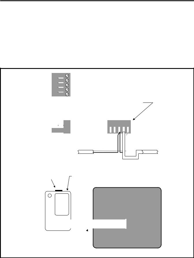
The SAMMS-MV device connects to the SEAbus™ RS-485 via the 5 pin plug on the Communications Module CM-1. The communications connections are illustrated in Figure 2.3. Refer to Installing the ACCESS System (manual no. SG-6028), for detailed information on connecting the SAMMS-MV device to the ACCESS network.
|
|
|
|
|
|
|
|
|
|
|
|
|
|
|
|
|
|
1 |
= - |
|
|
|
|
|
|
|
|
|
|
|
|
|
|
|
|
|
|
|
|
|
|
|
|
|
|
|
|
|
|
|
|
|
2 |
= GND |
|
|
|
|
|
|
|
|
|
|
|
|
|||
|
|
|
|
|
|
|
|
|
|
|
|
|
|
|
|
|
|
|
|
|
|
|
|
|
|
|
|
|
|
|||||
|
|
|
|
|
|
|
|
|
|
|
|
|
|
|
|
|
|
3 |
= + |
|
|
|
|
|
|
|
|
|
|
|
|
|
|
|
|
|
|
|
|
|
|
|
|
|
|
|
|
|
|
|
|
|
|
|
|
|
|
|
|
|
|
|
|
|
|
|
|
||
|
|
|
|
|
|
|
|
|
|
|
|
|
|
|
|
|
|
|
|
|
|
|
|
|
|
|
|
|
|
|
|
|||
|
|
|
|
|
|
|
|
|
|
|
|
|
|
|
|
|
|
4 |
= 12VDC+ |
|
|
|
|
|
|
|
|
|
|
|
|
|||
|
|
|
|
|
|
|
|
|
|
|
|
|
|
|
|
|
|
|
|
|
|
|
|
|
|
|
|
|
|
|||||
|
|
|
|
|
|
|
|
|
|
|
|
|
|
|
|
|
|
|
|
|
|
|
|
|
|
|
|
|
|
|||||
|
|
|
|
|
|
|
|
|
|
|
|
|
|
|
|
|
|
5 |
= 12VDC- |
|
|
|
|
|
|
|
|
|
|
|
|
|||
|
|
|
|
|
|
|
Top View |
|
|
|
|
|
|
|
|
|
|
|
|
|||||||||||||||
|
|
|
|
|
|
|
|
|
Proper make-up of 5 pin plug |
|||||||||||||||||||||||||
|
|
|
|
|
|
|
|
|
|
|
|
|
|
|
|
|
|
|
|
|||||||||||||||
|
|
|
|
|
|
|
|
|
|
|
|
|
|
|
|
|
|
|
|
|
|
|
Rear View |
|||||||||||
|
|
|
|
|
|
|
|
|
|
|
|
|
|
|
|
|
|
|
5 |
4 |
3 |
2 |
1 |
|
||||||||||
|
|
|
|
|
|
|
|
|
|
|
|
|
|
|
|
|
|
|
12Vdc(-) |
|
|
|
|
|
|
|
|
|
|
|
|
|
|
|
|
|
|
|
|
|
|
|
|
|
|
|
|
|
|
|
|
|
|
|
|
|
|
|
|
|
|
|
|
|
|
|
|
|
|
|
|
|
|
|
|
|
|
|
|
|
|
|
|
|
|
|
|
|
|
|
|
|
|
|
|
|
|
|
|
|
|
|
|
|
|
|
|
|
|
|
|
|
|
|
|
|
|
|
|
|
|
|
|
|
|
|
|
|
|
|
|
|
|
|
|
|
|
|
|
|
|
|
|
|
|
|
|
|
|
|
|
|
|
|
|
|
|
|
|
|
|
|
|
|
|
|
|
|
|
|
|
|
|
|
|
|
|
|
|
|
|
Side View |
|
|
|
|
|
|
|
|
|
|
|
|
|
|
|
||||||||||||
|
|
|
|
|
|
|
|
|
|
|
|
|
|
|
|
|
|
|
|
|
|
|
|
|||||||||||
|
|
|
|
|
|
|
|
12Vdc(+) |
|
|
|
|
|
|
|
|
|
WHT |
||||||||||||||||
|
|
|
|
|
|
|
|
|
|
|
|
|
|
|
|
|
|
|
|
|
|
|
|
|
|
|
|
|||||||
|
|
|
|
|
|
|
|
|
|
|
|
|
|
|
|
|
|
|
|
|
|
BLK |
|
|
|
|
|
|
||||||
|
|
|
|
|
|
|
|
|
|
|
|
|
|
|
|
|
|
|
Comm Cable |
|
|
|
|
|
|
|
|
|
|
|
Comm Cable |
|||
|
|
|
|
|
|
|
|
|
|
|
|
|
|
|
|
|
|
|
|
|
|
|
|
|
|
|
|
|
|
Shield |
||||
5 pin plug |
SAMMS |
|
|
|
|
|
|
|
|
|
|
|
|
|||||||||||||||||||||
Communications |
|
|
|
|
|
|
|
|
|
|
|
|
||||||||||||||||||||||
|
|
|
|
|
|
|
|
|
|
|
|
|
|
|
|
|
|
|
|
|
|
|
|
|
|
|
|
|
|
|||||
|
|
|
|
|
|
|
|
|
|
|
|
|
|
|
|
|
|
Module |
|
|
|
|
|
|
|
|
|
|
|
|
||||
12345 |
|
|
CM-1 |
|
|
|
|
|
|
|
|
|
|
|
|
|||||||||||||||||||
|
|
|
|
|
|
|
|
|
|
|
|
|
|
|
|
|
|
|
|
|
|
|
|
|
|
|
|
|
|
|
|
|
|
|
|
|
|
|
|
|
|
|
|
|
|
|
|
|
|
|
|
|
|
|
|
|
|
|
|
|
|
|
|
|
|
|
|
|
|
|
|
|
4 |
|
|
|
|
|
|
|
|
|
|
|
|
|
|
|
|
|
|
|
|
|
|
|
|
|
|
|
|
|
|
|
|
|
|
|
|
|
|
|
|
|
|
|
|
|
|
|
|
|
|
|
|
|
|
|
|
|
|
|
|
|
|
|
|
|
|
|
|
|
3 |
|
|
|
|
|
|
|
|
|
|
|
|
|
|
|
|
|
|
|
|
|
|
|
|
|
|
|
|
|
|
|
|
|
|
|
|
|
|
|
|
|
|
|
|
|
|
|
|
|
|
|
|
|
|
|
|
|
|
|
|
|
|
|
|
|
|
|
|
|
2 |
|
|
|
|
|
|
|
|
|
|
|
|
|
|
|
|
|
|
|
|
|
|
|
|
|
|
|
|
|
|
|
|
|
|
|
|
|
|
|
|
|
|
|
|
|
|
|
|
|
|
|
|
|
|
|
|
|
|
|
|
|
|
|
|
|
|
|
|
|
1 |
|
|
|
|
|
|
|
|
|
|
|
|
|
|
|
|
|
|
|
|
|
|
|
|
|
|
|
|
|
|
|
|
|
|
|
|
|
|
|
|
|
|
|
|
|
|
|
|
|
|
|
|
|
|
|
|
|
|
|
|
|
|
|
|
|
|
|
|
|
|
|
|
|
|
|
|
|
|
|
|
|
|
|
|
|
|
|
|
|
|
|
|
|
|
|
|
|
|
|
|
|
Ribbon cable assembly
Rear view of the SAMMS-MV device
Figure 2.3 SAMMS-MV device communications connections
10
3 Operating the SAMMS-MV Device
3 Operating the SAMMS-MV Device
This section explains how to operate the SAMMS-MV device.
3.1 Password Protection
Changing the settings of the SAMMS-MV device requires the use of the Hand-Held Communicator (HHC) in the program mode. To access the program mode, the user needs a password. The SAMMS-MV device is shipped from the factory with the password “0000.” This password can be changed by the user as described in section 3.29.1. Display of data using the HHC does not require use of a password.
3.2 Using the Reset/Test Push Button
The Reset/Test pushbutton is located at the bottom center of the front panel of the SAMMS-MV device as illustrated in Figure 3.1. You press this pushbutton to manually reset the SAMMS-MV device after a fault or a trip condition occurs so that the motor can be restarted. You can also use the Reset/Test pushbutton to perform a lamp test or an overload relay test.
3.2.1 Performing a Lamp Test
To test the diagnostic LEDs, the control LEDs and the light bars on the front panel, use the following procedure:
1.Press and hold the Reset/Test pushbutton for one to two seconds.
2.Release the Reset/Test pushbutton. (All LEDs and light bars on the front panel illuminate for two seconds.)
If a fault or trip condition exists when you press the Reset/Test pushbutton, the device performs a reset instead of a lamp test.
Figure 3.1 Front view of SAMMS-MV
3.2.2 Performing an Overload Relay Test
You may perform an overload relay test whenever the motor is stopped. Use the following procedure to perform an overload relay test.
1.Press and hold the Reset/Test pushbutton for at least the duration of the class time. The class time is set by accessing function F7. If you need to know how to access function F7, see Section 3.29. If you release the Reset/Test pushbutton before the duration of the class time, the device performs a lamp test. If a fault or trip condition exists when you press the Reset/Test pushbutton, the device performs a reset instead of a lamp test.
2.Continue to hold down the Reset/Test pushbutton. After reaching the class time duration, the Impending Trip and the Phase Unbalance LEDs illuminate.
3.Release the Reset/Test pushbutton. The Impending Trip and Phase Unbalance LEDs go off, and the Overload Trip LED illuminates for two seconds. If the SAMMS-MV device is tripped, it is automatically reset at the end of the overload relay test.
Use the following procedure to reset the SAMMS-MV device after a trip event.
1.Press the Reset/Test pushbutton.
2.Release the Reset/Test pushbutton. The device resets the alarm LEDs. If the motor has cooled sufficiently, you can restart the motor.
3.3 Motor Control
You can configure the SAMMS-MV device to perform many motor starting and control functions. These functions include basic across-the-line, to more complicated reversing, twospeed, and reduced-voltage starting. The SAMMS-MV device stores in its memory the executable code representing the ladder diagram for the user’s control application. The SAMMS-MV device and ladder diagram code replace the conventional control logic defined by wired interconnection of electromechanical timers, control relays, pushbuttons, selector switches, and pilot lights. A library of over 40 standard ladder diagrams available for the SAMMS-MV device covers most applications. In addition to the standard ladders, you can construct custom ladder diagrams, using optional software, to handle special applications.
Figures 3.2 and 3.3 illustrate the ladder symbols representing input and output devices available for the SAMMS-MV device. The circular symbols represent output devices such as contactor coil drivers, pilot LEDs on the front panel of the SAMMS-MV device, software time-delay relays and software control relays. All other symbols represent input devices such as software auxiliary contacts, remote AC inputs, front-panel pushbuttons, and software timer instantaneous and timed contacts.
11
3 Operating the SAMMS-MV Device
3.4 Output Devices
You can use the following SAMMS-MV output devices:
AC Outputs
The SAMMS-MVX device provides up to three AC coil drivers capable of driving contactors up to size H6, while SAMMS-MVE provides one coil driver.
Control Relays
The device provides up to eight software-controlled relays. These relays are helpful in local two-wire and other applications requiring maintained contacts.
Timing Relays
The SAMMS-MV device contains four internal software timing relays. You can configure all four timers as on-delay timers; however, if needed, you can configure the two adjustable timers (timing relays TR1 and TR2) as either on-delay or off-delay timers. Using the Hand Held Communicator, you can program timing relays TR1 and TR2 from 0 through 200 seconds (functions F13 and F14). Timing relay TR3 has a fixed 1 second delay, and timing relay TR4 has a fixed 30 seconds delay. Table 3.1 illustrates the type of timers used on the device and their ranges.
Timer |
Type |
Time (in seconds) |
|
|
|
TR1 |
Programmable on-delay or |
0 - 200 |
|
off-delay |
|
|
|
|
TR2 |
Programmable on-delay or |
0 - 200 |
|
off-delay |
|
|
|
|
TR3 |
Fixed on-delay |
1 |
|
|
|
TR4 |
Fixed on-delay |
30 |
Table 3.1 Types of software tming relays
Pilot LEDs
The SAMMS-MVX device contains three light bars on the front panel, while the SAMMS-MVE contains two light bars. Light bar L1 is reserved and must be used as the STOP or OFF LED. You can configure L2 and L3 at your discretion. The Hand, Off and Auto LEDs correspond to the Hand, Off and Auto pushbuttons on the front panel as illustrated in Figure 3.4. You can use the Incomplete Sequence LED in reduced-voltage applications or to verify contactor operation. Refer to Figure 3.4 for the location of the LEDs and Table 3.2 for a description of the LED states.
Flashing Pilot LEDs
The front panel contains two or three flashing light bars that indicate various conditions such as on-delay timing. These flashing light bars, L1, L2 and L3 as defined above, indicate different output devices if they are flashing rather than if they are on constantly. Refer to Figure 3.4 for an illustration of pilot LEDs.
3.5 Input Devices
You can use the following input devices with the SAMMS-MV device.
Remote AC Inputs
For SAMMS-MVX you can use four 120 VAC or VDC inputs for remote control, or you can use one input for SAMMS-MVE.
Front Panel Pushbuttons
The SAMMS-MV device has six front-panel pushbuttons for local control of the device. You must use pushbutton 1 (PB1) for stopping the motor. You must use three of the pushbuttons (PB4-PB6) for the Hand, Off and Auto functions if these functions are used in your configuration. If these functions are not used, you may use PB4-PB6 for other functions. You can configure the other two pushbuttons (PB2 and PB3) at your discretion. Refer to Figure 3.4 for assignment of pushbuttons. Insert labels are used to identify the function associated with each pushbutton or light bar.
Software Auxiliary Contacts
Any number of internal (software) auxiliary contacts can be configured. These contacts show either a normally open (NO) or normally closed (NC) status. You can set up these auxiliary contacts using the SAMMS-MV software. Through the SAMMS-MV software, the pilot LEDs also have auxiliary contacts.
|
STATE |
|
|
|
|
LED |
On |
Flashing |
|
|
|
Current |
> 40% |
20 - 40% |
Unbalance |
|
|
|
|
|
Impending Trip |
> 110% |
> 100% - <110% |
|
|
|
Overload Trip |
Trip |
Start Inhibit |
|
|
|
Incomplete |
Trip |
|
Sequence |
|
|
|
|
|
External |
Trip: Loss of Load |
Alarm: Loss of |
Trip/Alarm |
or Jam or RTD |
Load or Process |
|
|
Current |
|
|
|
CPU Fault |
Trip: CPU Failure or |
|
|
Low Voltage |
|
|
|
|
Ground Fault |
Trip |
Alarm |
|
|
|
Light bar (L1) |
Stop or Off |
Off Delay Timer |
|
|
Timing |
|
|
|
Light bar (L2) |
Start, On, Forward, |
On Delay Timer |
|
Low Speed, Right |
Timing |
|
|
|
Light bar (L3) |
Reverse, High |
On Delay Timer |
|
Speed, Left |
Timing |
Table 3.2 Description of pilot LEDs
Software Timer Inputs
Each timer has an unlimited number of normally open (NO) and normally closed (NC) contacts. Timers configured as on-delay timers have an unlimited supply of normally open timed-closed (NOTC), and normally closed timed-open (NCTO) contacts. Timers configured as off-delay timers have an unlimited supply of normally open timed-open (NOTO), and normally closed timed-closed (NCTC) contacts.
Communications Inputs
A serial, RS-485 communications port is located on the back of the device for external communications.
12

3 Operating the SAMMS-MV Device
The communications inputs must be included in the ladder logic (control circuit).
3.6 Ladder Diagrams
3.6.1 Library of Standard Ladder Diagrams
The SAMMS-MV library of more than 40 ladder diagrams covers most standard motor control applications. Table 3.3 lists the standard control circuits and the input and output assignments for the library. You can use the library with the following starter types:
∙across-the-line, non-reversing
∙across-the-line, reversing
∙two-speed, two winding
∙two-speed, one-winding, constant or variable torque
∙two-speed, one-winding, constant horsepower
∙reduced-voltage, autotransformer
∙reduced-voltage, reactor
For each starter type, the library includes seven control types:
∙local two-wire
∙local three-wire
∙local three-wire, remote two-wire
∙local two-wire, remote two-wire
∙local three-wire, remote three-wire
∙remote two-wire
∙remote three-wire
SAMMS-MVE has seven preloaded circuits (ladder diagrams) for use with across-the-line (FVNR) applications. SAMMS-MVX may be used with any of the circuits.
For details on the library of standard ladder diagrams, refer to the SAMMS Standard Circuit Manual.
3.6.2 Custom Ladder Diagrams
For special motor control applications not covered by the library of standard ladders, you can construct custom ladder diagrams using the input and output devices and their associated symbols for the SAMMS-MV device. Siemens personnel can build these custom ladder diagrams or you can build your own. You can purchase an optional IBM PC-compatible software package to develop custom ladder diagrams for special control applications. The package also includes a library of standard symbols. The package enables you to reconfigure existing SAMMS-MV devices to meet changing plant needs. Refer to the Custom Software Manual for the SAMMS device, Bulletin CP 3291.
Figure 3.2 Ladder symbols used with the SAMMS-MV device (sheet 1)
13

3 Operating the SAMMS-MV Device
Figure 3.3 Ladder symbols used with the SAMMS-MV device (sheet 2)
1 2 3 4 5 6 7 8 9 10 11 12 13 14 15 16
STOP or OFF |
|
|
PB6 |
AUTO or |
||
SAMMS-MVX |
|
L1 |
|
|||
|
|
|
||||
|
Current |
|
VARIABLE |
|||
|
|
|
|
|||
|
|
|
Unbalance |
|
||
|
|
|
|
|
|
|
LED |
LED on |
LED Flashing |
|
|
|
|
Current |
VARIABLE |
|
|
PB5 |
|
|
> 40% |
20 - 40% |
|
|
OFF or |
||
Unbalance |
|
|
L2 |
Impending |
|
|
Impending |
> 110% |
> 100% |
|
VARIABLE |
||
Trip |
|
< 110% |
|
Trip |
|
|
Overload |
|
Start |
|
|
|
|
Trip |
VARIABLEInhibit |
|
|
|
|
|
|
Overload |
|
|
|
PB4 |
HAND or |
|
|
|
L3 |
|
||
Incomplete |
Trip |
|
|
|
||
|
Overload |
|
VARIABLE |
|||
Sequence |
|
|
||||
|
|
|
||||
External |
Trip: Loss |
Alarm: Loss |
Trip |
|
||
|
|
|
|
|||
of Load,or |
of Load or |
|
|
|
|
|
Trip Alarm |
|
|
|
|
||
Jamor |
Prcs Current |
|
|
PB3 |
|
|
|
|
|
VARIABLE |
|||
|
RTD input |
|
CPU |
Incomplete |
|
|
CPU |
Trip: CPU |
|
|
|
||
|
Fault |
Sequence |
|
|
||
Failure or |
|
|
|
|||
Fault |
|
|
|
|||
Low Voltage |
|
|
|
|
|
|
|
|
|
|
|
|
|
Ground |
Trip |
Alarm |
|
|
PB2 |
VARIABLE |
Fault |
|
|
|
|
|
|
|
|
|
Ground |
External |
|
|
|
|
|
|
|
||
|
|
|
Fault |
Trip/Alarm |
|
|
|
|
|
|
Reset/Test |
PB1 |
STOP or OFF |
|
|
|
Ready |
|
|
|
|
|
|
|
|
|
|
Figure 3.4 Assignment of pushbuttons and light bars 14
Loading...