


 Loading...
SINAMICS S120
1FW6 built-in torque motors
Configuration Manual · 05/2009
SINAMICS
s

SINAMICS S120
Drive Technology
1FW6 Built-in torque motors
Configuration Manual
05/2009
6SN1197-0AE00-0BP3
Preface
General safety guidelines |
1 |
|
|
|
|
Description of the motor |
2 |
|
Motor components of the |
|
|
3 |
||
built-in motor and options |
||
|
|
|
Coupled motors |
4 |
|
|
|
|
Configuring the motor |
5 |
|
|
|
|
Motor assembly |
6 |
|
|
|
|
System integration |
7 |
|
|
|
|
Interfaces |
8 |
|
|
|
|
Commissioning |
9 |
|
|
|
|
Operation |
10 |
|
|
|
|
Maintenance and repairs |
11 |
|
|
|
|
Storage and transport |
12 |
|
|
|
|
Environmental compatibility |
13 |
|
Technical data and |
|
|
14 |
||
characteristics |
||
Installation |
|
|
15 |
||
drawings/Dimension |
||
drawings |
|
|
|
|
|
Appendix |
A |
|
|
|

Legal information
Warning notice system
This manual contains notices you have to observe in order to ensure your personal safety, as well as to prevent damage to property. The notices referring to your personal safety are highlighted in the manual by a safety alert symbol, notices referring only to property damage have no safety alert symbol. These notices shown below are graded according to the degree of danger.
 DANGER
indicates that death or severe personal injury will result if proper precautions are not taken.
 WARNING
indicates that death or severe personal injury may result if proper precautions are not taken.
 CAUTION
with a safety alert symbol, indicates that minor personal injury can result if proper precautions are not taken.
CAUTION
without a safety alert symbol, indicates that property damage can result if proper precautions are not taken.
NOTICE
indicates that an unintended result or situation can occur if the corresponding information is not taken into account.
If more than one degree of danger is present, the warning notice representing the highest degree of danger will be used. A notice warning of injury to persons with a safety alert symbol may also include a warning relating to property damage.
Qualified Personnel
The product/system described in this documentation may be operated only by personnel qualified for the specific task in accordance with the relevant documentation for the specific task, in particular its warning notices and safety instructions. Qualified personnel are those who, based on their training and experience, are capable of identifying risks and avoiding potential hazards when working with these products/systems.
Proper use of Siemens products
Note the following:
 WARNING
Siemens products may only be used for the applications described in the catalog and in the relevant technical documentation. If products and components from other manufacturers are used, these must be recommended or approved by Siemens. Proper transport, storage, installation, assembly, commissioning, operation and maintenance are required to ensure that the products operate safely and without any problems. The permissible ambient conditions must be adhered to. The information in the relevant documentation must be observed.
Trademarks
All names identified by ® are registered trademarks of the Siemens AG. The remaining trademarks in this publication may be trademarks whose use by third parties for their own purposes could violate the rights of the owner.
Disclaimer of Liability
We have reviewed the contents of this publication to ensure consistency with the hardware and software described. Since variance cannot be precluded entirely, we cannot guarantee full consistency. However, the information in this publication is reviewed regularly and any necessary corrections are included in subsequent editions.
Siemens AG |
Ordernumber: 6SN1197-0AE00-0BP3 |
Copyright © Siemens AG 2009. |
Industry Sector |
05/2009 |
Technical data subject to change |
Postfach 48 48 |
|
|
90026 NÜRNBERG |
|
|
GERMANY |
|
|
Preface
Information on the documentation
At http://www.siemens.com/motioncontrol/docu information is available on the following topics:
●Ordering documentation
Here you can find an up-to-date overview of publications
●Downloading documentation
Links to more information for downloading files from Service & Support.
●Researching documentation online
Information on DOConCD and direct access to the publications in DOConWeb.
●Compiling documentation individually on the basis of Siemens content with the My Documentation Manager (MDM), see http://www.siemens.com/mdm
The My Documentation Manager offers you a range of features for creating your own machine documentation.
●Training and FAQs
Information on the range of training courses and FAQs (frequently asked questions) are available via the page navigation.
Target group
This manual is aimed at planning, project, and design engineers as well as electricians, fitters, and service personnel.
Benefits
This configuration manual enables the target group to comply with the rules and guidelines that apply when torque motors are configured. It helps you select products and functions.
Standard scope
This documentation describes the functionality of the standard version. Extensions or changes made by the machine manufacturer are documented by the machine manufacturer.
Other functions not described in this documentation might be able to be executed in the drive system. This does not, however, represent an obligation to supply such functions with a new delivery or when servicing.
For reasons of clarity, this documentation does not contain all the detailed information about all types of the product and cannot cover every conceivable case of installation, operation or maintenance.
1FW6 Built-in torque motors |
5 |
Configuration Manual, 05/2009, 6SN1197-0AE00-0BP3 |

Preface
Technical Support
If you have any technical questions, please contact our hotline:
|
Europe / Africa |
Phone |
+49 180 5050 222 |
Fax |
+49 180 5050 223 |
|
0.14 €/min. from German landlines (mobile call charges may differ) |
Internet |
http://www.siemens.com/automation/support-request |
|
|
|
America |
Telephone |
+1 423 262 2522 |
Fax |
+1 423 262 2200 |
mailto:techsupport.sea@siemens.com |
|
|
|
|
Asia / Pacific |
Telephone |
+86 1064 757 575 |
Fax |
+86 1064 747 474 |
mailto:support.asia.automation@siemens.com |
Note
For technical support telephone numbers for different countries, go to:
http://www.automation.siemens.com/partner
Questions about this documentation
Please send any questions about the technical documentation (e.g. suggestions, corrections) to the following fax number or E-Mail address:
Fax |
+49 (0) 9131 / 98-2176 |
E-mail to: docu.motioncontrol@siemens.com |
A fax form is available in the appendix of this document.
Internet address for products
http://www.siemens.com/motioncontrol
6 |
1FW6 Built-in torque motors |
Configuration Manual, 05/2009, 6SN1197-0AE00-0BP3 |

Preface
EC Declaration of Conformity
The EC Declaration of Conformity (to Low-Voltage Directive 2006/95/EC) is available at the following Internet address in the folder "Drive Technology":
http://support.automation.siemens.com/WW/llisapi.dll?func=cslib.csinfo&lang=de&siteid=csiu
s&objid=19183574
If you do not have access to the Internet, contact your local Siemens office to obtain a copy of the EC Declaration of Conformity.
1FW6 Built-in torque motors |
7 |
Configuration Manual, 05/2009, 6SN1197-0AE00-0BP3 |
Table of contents
|
Preface |
...................................................................................................................................................... |
5 |
1 |
General ........................................................................................................................safety guidelines |
13 |
|
|
1.1 ......................................................................... |
Observing and complying with safety guidelines |
14 |
|
1.2 ....................................................................................... |
Handling direct drives and components |
15 |
|
1.3 ....................................................................................................... |
Use for the intended purpose |
16 |
|
1.4 ............................................................................................. |
Danger from strong magnetic fields |
17 |
|
1.5 ............................................................................................................... |
Electrical shock hazard! |
20 |
|
1.6 ............................................................................................................... |
Attaching warning signs |
20 |
|
1.7 ..................................................................................................... |
Pictograms supplied for 1FW6 |
21 |
2 |
Description ...........................................................................................................................of the motor |
23 |
|
|
2.1 ..................................................................................................................................... |
Properties |
23 |
|
2.1.1 ...................................................................................................................................... |
Overview |
23 |
|
2.1.2 ........................................................................................................................................ |
Benefits |
24 |
|
2.1.3 .................................................................................................................................. |
Applications |
25 |
|
2.2 ........................................................................................................................ |
Technical features |
25 |
|
2.3 ......................................................................................................... |
Selection and ordering data |
29 |
|
2.4 ........................................................................................................................ |
Order designation |
34 |
|
2.4.1 .............................................................................................. |
Structure of the order designations |
34 |
|
2.4.2 ........................................................................................... |
Standard 1FW6 built - in torque motor |
35 |
|
2.4.3 .................................................................................................... |
Stator as individual component |
36 |
|
2.4.4 ..................................................................................................... |
Rotor as individual component |
37 |
|
2.4.5 .......................................................................................................... |
Round sealing ring (O ring) |
37 |
|
2.4.6 ......................................................................................................... |
Cooling connection adapter |
38 |
|
2.4.7 ............................................................................................................................. |
Plug connector |
38 |
|
2.4.8 ............................................................................................................................. |
Ordering notes |
38 |
|
2.4.9 ....................................................................................................................... |
Ordering examples |
39 |
|
2.5 ......................................................................................................................... |
Motor rating plate |
40 |
3 |
Motor components ................................................................................of the built-in motor and options |
41 |
|
|
3.1 ............................................................................................. |
Overview of the motor construction |
41 |
|
3.2 ............................................................................................................. |
Thermal motor protection |
44 |
|
3.2.1 ....................................................................................... |
Description of the temperature sensors |
44 |
|
3.2.2 ........................................................ |
Evaluation of the temperature sensors for motor protection |
48 |
|
3.3 ......................................................................................................................................... |
Cooling |
48 |
|
3.3.1 ............................................................................................................................. |
Cooling circuits |
50 |
|
3.3.2 ......................................................................................................................................... |
Coolant |
52 |
4 |
Coupled .......................................................................................................................................motors |
55 |
|
|
4.1 ............................................................................................ |
Parallel operation of several motors |
55 |
|
4.1.1 ...................................................................................... |
Power connection for parallel operation |
56 |
1FW6 Built-in torque motors |
9 |
||
Configuration Manual, 05/2009, 6SN1197-0AE00-0BP3 |
|||

Table of contents
|
4.1.2 |
Janus arrangement..................................................................................................................... |
59 |
5 |
Configuring the motor.............................................................................................................................. |
61 |
|
|
5.1 |
Procedure.................................................................................................................................... |
61 |
|
5.1.1 |
General mechanical conditions................................................................................................... |
63 |
|
5.1.2 |
Specification of the duty cycle..................................................................................................... |
63 |
|
5.1.3 |
Torque-time diagram................................................................................................................... |
64 |
|
5.1.4 |
Selecting the motors .................................................................................................... |
............... 66 |
|
5.1.5 |
Uneven current load.................................................................................................................... |
67 |
|
5.1.6 |
Motor torque-speed diagram.............................................................................................. |
......... 67 |
|
5.1.7 |
Torque-speed requirements........................................................................................................ |
68 |
|
5.1.8 |
More than one torque motor on one axes................................................................................... |
69 |
|
5.1.9 |
Checking the moments of inertia ................................................................................................ |
69 |
|
5.1.10 |
Selecting the drive system components for the power connection............................................. |
70 |
|
5.1.11 |
Calculating the required infeed power ........................................................................................ |
70 |
|
5.2 |
Example(s).................................................................................................................................. |
71 |
|
5.3 |
Short-time duty S2 and intermittent duty S3............................................................................... |
76 |
6 |
Motor assembly ....................................................................................................................................... |
79 |
|
|
6.1 |
Motor assembly........................................................................................................................... |
79 |
|
6.1.1 |
Procedure for installing the motor............................................................................................... |
84 |
|
6.1.2 |
Cooler connection....................................................................................................... |
................ 88 |
|
6.1.3 |
Information on routing cables...................................................................................................... |
90 |
|
6.1.4 |
Checking the work carried out .................................................................................................... |
91 |
|
6.1.5 |
Installation examples................................................................................................................... |
92 |
|
6.2 |
Protecting the motor components............................................................................................. |
100 |
7 |
System integration................................................................................................................................. |
101 |
|
|
7.1 |
System requirements................................................................................................................ |
101 |
|
7.2 |
Encoders................................................................................................................................... |
106 |
|
7.3 |
Bearings.................................................................................................................................... |
109 |
|
7.4 |
Braking concepts.......................................................................................................... |
............. 109 |
8 |
Interfaces............................................................................................................................................... |
113 |
|
|
8.1 |
Overview................................................................................................................................... |
113 |
|
8.2 |
Electrical connections ............................................................................................................... |
142 |
|
8.2.1 |
Power connection...................................................................................................................... |
143 |
|
8.2.2 |
Signal connection...................................................................................................................... |
143 |
|
8.2.3 |
Shielding, grounding, and equipotential bonding...................................................................... |
145 |
|
8.2.4 |
Requirements for the motor supply cables ............................................................................... |
146 |
|
8.3 |
Cooler connection..................................................................................................................... |
146 |
9 |
Commissioning...................................................................................................................................... |
159 |
|
|
9.1 |
Safety guidelines for commissioning......................................................................................... |
159 |
|
9.2 |
Procedure.................................................................................................................................. |
162 |
10 |
Operation............................................................................................................................................... |
165 |
|
|
10.1 |
Safety guidelines for operation ................................................................................................. |
165 |
|
10.2 |
Dealing with faults...................................................................................................... |
............... 165 |
10 |
|
|
1FW6 Built-in torque motors |
|
Configuration Manual, 05/2009, 6SN1197-0AE00-0BP3 |
||
|
|
Table of contents |
11 |
Maintenance and repairs....................................................................................................................... |
167 |
|
11.1 |
167 |
|
11.2 |
169 |
|
11.3 |
169 |
|
11.4 |
170 |
12 |
Storage and transport............................................................................................................................ |
171 |
|
12.1 |
171 |
|
12.2 |
172 |
13 |
Environmental compatibility................................................................................................................... |
173 |
|
13.1 |
173 |
|
13.2 |
173 |
|
13.2.1 |
173 |
|
13.2.2 |
174 |
|
13.2.3 |
174 |
14 |
Technical data and characteristics......................................................................................................... |
175 |
|
14.1 |
175 |
|
14.2 |
182 |
|
14.2.1 |
182 |
|
14.2.2 |
190 |
|
14.2.3 |
198 |
|
14.2.4 |
206 |
|
14.2.5 |
227 |
|
14.2.6 |
248 |
|
14.2.7 |
268 |
15 |
Installation drawings/Dimension drawings............................................................................................. |
279 |
|
15.1 |
279 |
|
15.2 |
280 |
|
15.3 |
282 |
A |
Appendix |
291 |
|
A.1 |
291 |
|
A.1.1 ........... |
291 |
|
A.1.2 ........................................................................................... |
292 |
|
A.1.3 .................................................................................. |
293 |
|
A.1.4 ......................................................................................... |
294 |
|
A.2 ............................................................... |
295 |
|
A.3 ................................................................................................................... |
296 |
|
Index...................................................................................................................................................... |
299 |
1FW6 Built-in torque motors |
11 |
Configuration Manual, 05/2009, 6SN1197-0AE00-0BP3 |
General safety guidelines |
1 |
Please observe all the relevant safety instructions to avoid personal and/or material damage. In particular, you must observe the safety instructions and notes regarding the powerful permanent magnets installed in the rotor of the built-in torque motor.
The rotor is secured in the stator by means of transportation locks and a spacer film. The original packaging for the built-in torque motor and the transportation locks (incl. the screws) are required for storage/transport purposes and should, therefore, be kept in a safe place. This documentation should also be kept in a safe place and made available to the personnel responsible.
Residual risks of power drive systems
When carrying out a risk assessment of the machine in accordance with the EU Machinery Directive, the machine manufacturer must consider the following residual risks associated with the control and drive components of a power drive system (PDS).
1.Unintentional movements of driven machine components during commissioning, operation, maintenance, and repairs caused by, for example:
–Hardware defects and/or software errors in the sensors, controllers, actuators, and connection technology
–Response times of the controller and drive
–Operating and/or ambient conditions not within the scope of the specification
–Parameterization, programming, cabling, and installation errors
–Use of radio devices / cellular phones in the immediate vicinity of the controller
–External influences / damage
2.Exceptional temperatures as well as emissions of light, noise, particles, or gas caused by, for example:
–Component malfunctions
–Software errors
–Operating and/or ambient conditions not within the scope of the specification
–External influences / damage
3.Hazardous shock voltages caused by, for example:
–Component malfunctions
–Influence of electrostatic charging
–Induction of voltages in moving motors
–Operating and/or ambient conditions not within the scope of the specification
–Condensation / conductive contamination
–External influences / damage
1FW6 Built-in torque motors |
13 |
Configuration Manual, 05/2009, 6SN1197-0AE00-0BP3 |

General safety guidelines
1.1Observing and complying with safety guidelines
4.Operational electrical, magnetic, and electromagnetic fields that can pose a risk to people with a pacemaker and/or implants or metallic objects if they are too close.
5.Release of environmentally hazardous materials and emissions during improper operation and / or improper disposal of components.
For more information about residual risks of the power drive system components, see the relevant chapters in the technical user documentation.
 DANGER
It may be dangerous for people to remain in the immediate proximity of the product – especially for those with pacemakers, implants or similar – due to electric, magnetic and electromagnetic fields (EMF) occurring as a consequence of operation.
The machine/system operator and the people present near the product must observe the relevant guidelines and standards! These are, for example, in the European Economic Area (EEA) the Electromagnetic Fields Directive 2004/40/EC and the standards EN 12198-1 to 12198-3 and in the Federal Republic of Germany the Employer's Liability Insurance Association Regulations for the Prevention of Industrial Accidents BGV 11, with the relevant rule BGR 11 "Electromagnetic Fields".
Then a risk assessment must be carried out for every workplace, activities for reducing dangers and exposure for people decided upon and implemented, as well as determining and observing exposure and danger areas.
1.1Observing and complying with safety guidelines
 DANGER
There is a danger of death, severe physical injury, and/or damage to property if the safety instructions are not observed and complied with.
It is essential that you observe the safety instructions in this documentation. This includes the special safety instructions in the individual sections.
Observe all warning and information plates.
Make sure that your end product satisfies all relevant standards and legal specifications. The applicable national, local, and machine-specific safety regulations and requirements must also be taken into account.
In addition to the safety instructions included in this documentation, the detailed specifications in the catalogs and offers also apply to the special motor versions.
Also observe the relevant operating instructions when working on the drive system.
14 |
1FW6 Built-in torque motors |
Configuration Manual, 05/2009, 6SN1197-0AE00-0BP3 |

General safety guidelines 1.2 Handling direct drives and components
1.2Handling direct drives and components
 DANGER
There is danger of death, serious bodily injury and/or property damage when untrained personnel is allowed to handle direct drives and/or their components.
Only personnel who are familiar with and who observe the safety guidelines are allowed to handle direct drives and their components.
Installation, commissioning, operation and maintenance may only be performed by qualified, trained and instructed personnel. The personnel must be thoroughly familiar with the content of this guide.
All work must be performed by at least two persons.
Note
Make sure that the information about the sources of danger and the safety measures is available at all times! Keep all the descriptions and safety guidelines concerning direct drives and their components if possible!
All descriptions and safety guidelines can also be requested from your local Siemens office.
1FW6 Built-in torque motors |
15 |
Configuration Manual, 05/2009, 6SN1197-0AE00-0BP3 |

General safety guidelines
1.3 Use for the intended purpose
1.3Use for the intended purpose
 DANGER
There is a risk of death, serious personal injury and/or serious material damage when direct drives or their components are used for a purpose for which they were not intended.
The motors are designed for industrial or commercial machines. It is prohibited to use them in areas where there is a risk of explosion (Ex-zone) unless they are designed expressly for this purpose (observe the separately enclosed additional instructions where applicable). If increased demands (e.g. touch protection) are made in special cases – for use in noncommercial systems – these conditions must be ensured on the machine side during installation.
Direct drives and their components may only be used for the applications specified by the manufacturer. Please contact your Siemens branch responsible if you have any questions on this matter.
The motors must be protected from dirt and contact with aggressive substances.
Special versions and design variants whose specifications vary from the motors described herein are subject to consultation with your Siemens branch.
The motors are designed for an ambient temperature range of -5 °C to +40 °C. Any alternative requirements specified on the rating plate must be noted! The on-site conditions must comply with the rating plate specifications and the condition specifications contained in this documentation. Any differences regarding approvals or country-specific guidelines must be taken into account separately.
 DANGER
The products included in the scope of delivery are exclusively designed for installation in a machine. Commissioning is prohibited until it has been established that the end product conforms with Directive 98/37/EC. All safety instructions must be observed and given to the end user for his/her information.
 DANGER
Risk of electric shock if a hazardous voltage is present on the stator when operated as a single component.
To ensure that the components have sufficient shock-hazard protection, voltage must only be applied to the motors once they have been installed.
16 |
1FW6 Built-in torque motors |
Configuration Manual, 05/2009, 6SN1197-0AE00-0BP3 |
General safety guidelines 1.4 Danger from strong magnetic fields
1.4Danger from strong magnetic fields
Occurrence of magnetic fields
Strong magnetic fields occur in the components of the motor that contain permanent magnets. The magnetic field strength of the motors results exclusively from the magnetic fields of the components with permanent magnets in the de-energized state. Electromagnetic fields also occur during operation.
Components with permanent magnets
 CAUTION
The permanent magnets of the 1FW6 torque motors are located in the rotor.
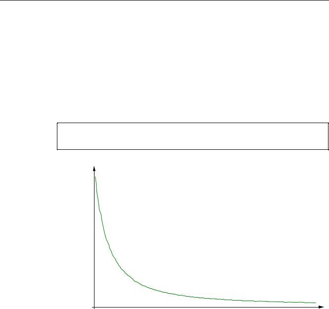
DSSUR[
0DJQHWLFIOX[GHQVLW\LQP7
DSSUR[
'LVWDQFH LQ PP
Figure 1-1 Schematic representation of the static magnetic field of a rotor, as a function of distance
1FW6 Built-in torque motors |
17 |
Configuration Manual, 05/2009, 6SN1197-0AE00-0BP3 |

General safety guidelines
1.4 Danger from strong magnetic fields
Danger from strong magnetic fields
 DANGER
Strong magnetic fields can pose a risk to personnel and cause damage.
With regard to the effect of strong magnetic fields on people, the work guideline BGV B 11 "Electromagnetic Fields" applies in Germany. This specifies all the requirements that must be observed in the workplace. In other countries, the relevant applicable national and local regulations and requirements must be taken into account.
People with active electrical component implants (e.g. pacemakers, insulin pumps), metal implants and magnetic or electrically conducting foreign bodies are urgently advised to avoid direct contact with components containing permanent magnets. This applies to, e.g., any work connected with assembly, maintenance or storage.
BGV B 11 specifies a limit value of 212 mT for static magnetic fields. This must be observed for distances greater than 20 mm from a rotor.
The requirements of BGV B 11 must also be taken into account with regard to strong magnetic fields (BGV B11 §14).
 DANGER
Personnel who are exposed to magnetic fields in their daily work must maintain a distance of at least 50 mm from a rotor.
Personnel with pacemakers must maintain a distance of at least 500 mm from a rotor.
Humans have no sensory organs for picking up strong magnetic fields and have no experience with them as a rule. Therefore, the magnetic forces of attraction emanating from strong magnetic fields are often underestimated.
The magnetic forces of attraction may be several kN in the vicinity of the motor components containing permanent magnets (within a distance of less than 100 mm). – Example: Magnetic attractive forces are equivalent to a mass of several hundred kilos, which can trap a part of the body (hands, fingers, feet etc.)!
18 |
1FW6 Built-in torque motors |
Configuration Manual, 05/2009, 6SN1197-0AE00-0BP3 |

General safety guidelines 1.4 Danger from strong magnetic fields
 DANGER
Strong attractive forces on magnetizable materials lead to a great danger of crushing in the vicinity of components with permanent magnets (distance less than 100 mm).
Do not underestimate the strength of the attractive forces!
Do not carry any objects made of magnetizable materials (e. g. watches, steel or iron tools) and/or permanent magnets close to the motor or close to a component with permanent magnets.
For the event of accidents when working with permanent magnets, the following objects must be on hand to free clamped body parts (hands, fingers, feet etc.):
a hammer (about 3 kg) made of solid, non-magnetizable material
two pointed wedges (wedge angle approx. 10° to 15°) made of solid, non-magnetizable material (e.g. hard wood)
First aid in the case of accidents involving permanent magnets
●Stay calm.
●Press the emergency stop switch and, where necessary, switch off the main switch if the machine is live.
●Administer FIRST AID. Call for further help if required.
●To free jammed body parts (e.g., hands, fingers, feet), pull apart components that are clamped together.
–To do this, use a hammer to drive a wedge into the separating rift
–Release the jammed body parts.
●If necessary, call for an EMERGENCY DOCTOR.
CAUTION
Magnetic fields can lead to a loss of data on magnetic or electronic data media and damage watches.
Keep all magnetic or electronic data media (e.g. credit cards, disks, etc.) and watches away from the rotor (< 100 mm).
1FW6 Built-in torque motors |
19 |
Configuration Manual, 05/2009, 6SN1197-0AE00-0BP3 |

General safety guidelines 1.5 Electrical shock hazard!
1.5Electrical shock hazard!
 DANGER
Electrical shock hazard! When an installed torque motor rotates, potentially dangerous voltages are induced at the cable ends of the motor.
Insulate terminals and leads in open cable ends or take measures to prevent torque motors that have been installed from rotating.
There is also a risk of compression.
 DANGER
Danger due to high leakage currents
If high leakage currents are present, more stringent requirements may apply to the PE conductor. Warning signs may also be required on the PDS. You can find more detailed information in the standard EN 61800-5-1.
Protective measures against residual voltages
 DANGER
There is a shock hazard danger due to the residual voltages at the motor terminals!
When the power supply voltage is switched-out, active parts of the motor can have a charge of more than 60 μC. In addition, at open-circuit cable ends - e.g. when a connector is withdrawn - even after the power has been disconnected, a voltage or more than 60 V can be present for 1 s. This is the reason that you must apply the appropriate measures to provide protection against residual voltages!
1.6Attaching warning signs
All danger areas must be identified by well visible warning and prohibiting signs (pictograms) in the immediate vicinity of the danger. The associated texts must be available in the language of the country in which the product is used.
20 |
1FW6 Built-in torque motors |
Configuration Manual, 05/2009, 6SN1197-0AE00-0BP3 |

General safety guidelines 1.7 Pictograms supplied for 1FW6
1.7Pictograms supplied for 1FW6
To indicate dangers, the following durable adhesive stickers are supplied:
|
Table 1- 1 |
Warning signs to BGV A8 / DIN 4844-2 and what they indicate |
|
||||
|
|
|
|
|
|
|
|
|
|
Sign |
|
Meaning |
Sign |
|
Meaning |
|
|
|
|
Warning: strong |
|
|
Warning: hand injuries |
|
|
|
|
magnetic field |
|
|
(D-W027) |
|
|
|
|
(D-W013) |
|
|
|
|
|
|
|
|
|
|
|
|
|
|
|
Warning: hazardous |
|
|
Warning: hot surfaces |
|
|
|
|
electric voltage |
|
|
(D-W026) |
|
|
|
|
(D-W008) |
|
|
|
|
|
|
|
|
|
|
|
|
Table 1- 2 |
Prohibiting signs to BGV A8 / DIN 4844-2 and what they indicate |
|
||||
|
|
|
|
|
|
||
|
|
Sign |
|
Meaning |
Sign |
|
Meaning |
|
|
|
|
No pacemakers |
|
|
No metal implants |
|
|
|
|
(D-P011) |
|
|
(D-P016) |
|
|
|
|
|
|
|
|
|
|
|
|
No metal objects or |
|
|
No magnetic or |
|
|
|
|
watches |
|
|
electronic data media |
|
|
|
|
(D-P020) |
|
|
(D-P021) |
|
|
|
|
|
|
|
|
1FW6 Built-in torque motors |
|
|
|
|
|
21 |
|
Configuration Manual, 05/2009, 6SN1197-0AE00-0BP3 |
|
|
|
||||
Description of the motor |
2 |
1FW6 built-in torque motor
2.1Properties
2.1.1Overview
1FW6 torque motors are designed as built-in motors for use in low-speed direct drives with a high torque output.
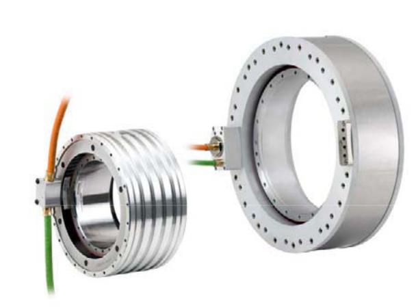
Built-in torque motors are liquid-cooled, permanent-magnet-excited, (high pole number) three-phase synchronous motors with hollow-shaft rotors. The motors are provided as builtin components which, on delivery, are secured together by means of transportation locks
1FW6 Built-in torque motors |
23 |
Configuration Manual, 05/2009, 6SN1197-0AE00-0BP3 |

Description of the motor 2.1 Properties
and spacer film. For a complete drive unit, an additional bearing and rotary transducer are required.
The product range includes 7 frame sizes (or external diameters), each with at least 4 different axis lengths. Each motor is available for at least two different speed ranges. The stator and rotor are equipped with flanges at both ends with centering surfaces and tapped holes, which allow them to be integrated in a machine.
Standards and regulations
The product complies with the standards relating to the Low-Voltage Directive stated in the EC Declaration of Conformity.
2.1.2Benefits
Features of the motors:
●Extremely high power density
●High torque with a compact design and low unit volume
●Wide range of types
●High overload capability (factor 1.6 to 2.2); the current input of the windings is adjusted in line with the Motor Modules in the SINAMICS S120 drive system.
●Low moment of inertia
●High degree of availability as there are no gearbox components in the mechanical drive transmission line which are subject to wear
●Water cooling to increase the rated power
●Directly flanged to the machine
●Cable outlet, axial, radial towards the outside or tangential for all frame sizes
As a result of water cooling, they fulfill high requirements regarding the thermal behavior within the machine assembly.
24 |
1FW6 Built-in torque motors |
Configuration Manual, 05/2009, 6SN1197-0AE00-0BP3 |

Description of the motor 2.2 Technical features
2.1.3Applications
In conjunction with the SINAMICS S120 drive system (booksize or blocksize format), the built-in torque motors can be used as a direct drive for the following machine applications:
●Rotary indexing machines, rotary tables, swivel axes
●Rotary axes (A, B, C axes in 5-axes machine tools)
●Rotary tables, rotary indexing machines, sub-machine assemblies
●Turret indexing and drum indexing for single-spindle and multi-spindle machines
●Dynamic tool magazines
●Rotating spindles in milling machines
●Roller and cylinder drives
●Infeed and handling axes
 WARNING
The motors cannot be operated directly on the supply system, but may only be operated with a suitable drive system.
Note
Note that when 1FW6 direct motors (torque motors) are used in fork heads for machine tools or robots, a license for US patent US5584621 and the associated international patent protection may be required.
2.2Technical features
Note
The values specified in the following table only apply in conjunction with the system prerequisites described in "System integration".
|
Table 2- 1 |
Standardversion of the 1FW6 torque motor |
|
|
|
|
|
|
Technical feature |
Version |
|
|
Motor type |
|
Synchronous motor with permanent magnet rotor, multi-pole (no. |
|
|
|
of rotor poles: 44 to 98) |
|
Design |
|
Individual components: stator, rotor |
|
Degree of protection to EN |
Motor: IP23 |
|
|
60034-5 and EN 60529 |
The final degree of protection (minimum degree of protection: |
|
|
|
|
IP54) of the built-in motor must be realized by the machine |
|
|
|
manufacturer. |
1FW6 Built-in torque motors |
|
25 |
|
Configuration Manual, 05/2009, 6SN1197-0AE00-0BP3 |
|||

Description of the motor 2.2 Technical features
Technical feature |
Version |
Cooling method |
Water cooling: |
|
Jacket cooling, size 1FW609, 1FW613, 1FW615 |
|
Integrated cooling, size 1FW616, 1FW619, 1FW623, 1FW629 |
Pressure in the cooling circuit |
Max. 10 bar (static) |
Cooler connection |
Motors with a cooling jacket: |
|
Must be connected by customer |
|
Motors with integrated cooling: |
|
Connection with/without cooling connection adapter (see |
|
"Installing the motor") |
Temperature sensor |
2 x PTC thermistor triplet with response threshold +130 /150 °C |
|
(to DIN 44081/44082) and 1 x KTY84 thermistor (to EN 60034- |
|
11) in the stator. |
Insulation of stator winding |
Temperature class 155 (F) |
according to EN 60034-1 |
|
|
|
Magnet material |
Rare earth material |
Connection, electrical |
Cable outlet: |
|
Axial |
|
radial outward |
|
tangential (not in the case of motors with single cores) |
|
Connection type: |
|
Permanently connected power and signal cables with open core |
|
ends |
|
Length: 2 m |
|
Permanently connected power cables with single cores and |
|
signal cables with open core ends |
|
Length: 1 m |
|
Permanently connected power and signal cables pre-assembled |
|
with connectors (not in the case of motors with single cores) |
|
Length: 0.5 m |
Motor supply cables |
For the specifications of the motor supply cables, see |
|
"Interfaces". |
Torque ripple |
≤ 1.5% M0 |
Ambient conditions for long-term storage, transport, and use in fixed locations
Based on DIN EN 60721-3-1 (for long-term storage), DIN EN 60721-3-2 (for transport), and DIN EN 60721-3-3 (for use in fixed, weather-protected locations)
Table 2- 2 |
Climatic ambient conditions |
|
|
|
|
Lower air temperature limit: |
- 5 °C |
|
Upper air temperature limit: |
+ 40 °C (deviates from 3K5) |
|
Lower relative humidity limit: |
5 % |
|
Upper relative humidity limit: |
85 % |
|
Rate of temperature fluctuations: |
< 0.5 K/min |
|
Condensation: |
Not permissible |
|
Formation of ice: |
Not permissible |
|
26 |
|
1FW6 Built-in torque motors |
|
Configuration Manual, 05/2009, 6SN1197-0AE00-0BP3 |
|

|
|
Description of the motor |
|
|
2.2 Technical features |
|
|
|
|
Long-term storage: |
Class 1K3 and class 1Z1 have a different upper relative humidity |
|
Transport: |
Class 2K2 |
|
Fixed location: |
Class 3K3 |
Storage, transport and operation permissible only in locations that are fully protected against the weather (in halls or rooms).
Table 2- 3 |
Biological ambient conditions |
|
|
|
|
Long-term storage: |
Class 1B1 |
|
Transport: |
|
Class 2B1 |
Fixed location: |
Class 3B1 |
|
Table 2- 4 |
Chemical ambient conditions |
|
|
|
|
Long-term storage: |
Class 1C1 |
|
Transport: |
|
Class 2C1 |
Fixed location: |
Class 3C2 |
|
|
|
Operating site in the immediate vicinity of industrial plants with chemical emissions |
Table 2- 5 |
Mechanically active ambient conditions |
|
|
|
|
Long-term storage: |
Class 1S2 |
|
Transport: |
|
Class 2S2 |
Fixed location: |
Class 3S1 |
|
1FW6 Built-in torque motors |
27 |
Configuration Manual, 05/2009, 6SN1197-0AE00-0BP3 |
Description of the motor 2.2 Technical features
Table 2- 6 Mechanical ambient conditions
Long-term storage: |
Class 1M2 |
Transport: |
Class 2M2 |
Fixed location: |
Class 3M3 |
UL approval
The torque motors described in this documentation have been approved by Underwriters Laboratories Inc. (USA) (UL).
Validity
Generally the approvals for the motor are listed on the rating plate. As a rule, these approvals are valid for the operating mode specified in the data sheets. More detailed information on the conditions for the validity of an approval can be obtained from your local Siemens office.
The installation conditions according to Underwriters Laboratories Inc. (USA) - UL for short - can be taken from the Conditons of Acceptability.
Direction of rotation
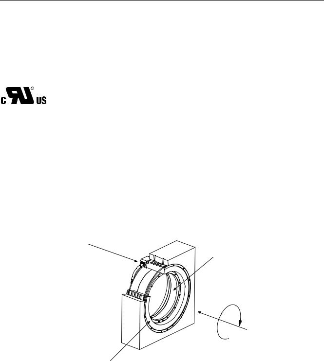
The rotor for the built-in torque motor rotates clockwise if the built-in torque motor is connected to phase sequence U, V, W. You can see this when you look at the A flange of the motor.
% IODQJH ZLWK FDEOH RXWOHW
&ORFNZLVH URWDWLRQ 7KH URWRU URWDWHV FORFNZLVHSKDVH VHTXHQFH 8 9 :
/LQH RI VLJKW WRZDUGV $ IODQJH
$ IODQJH
Figure 2-1 Line of sight for determining the direction of rotation
28 |
1FW6 Built-in torque motors |
Configuration Manual, 05/2009, 6SN1197-0AE00-0BP3 |

Description of the motor 2.3 Selection and ordering data
2.3Selection and ordering data
Table 2- 7 Built-in torque motors: overview (part 1 of 2)
Order desig. / |
Rated torque1) |
Max. torque |
Rated |
Max. current |
Max. speed at |
Max. speed at |
Size |
MN |
MMAX |
current1) IN |
IMAX |
2) |
2) |
|
|
|
|
rated torque |
max. torque |
|
|
in Nm |
in Nm |
in A |
in A |
nMAX,MN |
nMAX,MMAX |
|
|
|
|
|
in rpm |
in rpm |
1FW6090-xxB05-0Fxx |
113 |
179 |
5.6 |
9.5 |
140 |
46 |
1FW6090-xxB05-0Kxx |
109 |
179 |
7.4 |
13 |
250 |
140 |
1FW6090-xxB07-0Kxx |
154 |
251 |
9.5 |
16 |
220 |
120 |
1FW6090-xxB07-1Jxx |
142 |
251 |
13 |
26 |
430 |
270 |
1FW6090-xxB10-0Kxx |
231 |
358 |
7.9 |
13 |
82 |
8.7 |
1FW6090-xxB10-1Jxx |
216 |
358 |
14 |
26 |
270 |
170 |
1FW6090-xxB15-1Jxx |
338 |
537 |
15 |
26 |
150 |
78 |
1FW6090-xxB15-2Jxx |
319 |
537 |
23 |
43 |
310 |
200 |
1FW6130-xxB05-0Kxx |
241 |
439 |
9 |
18 |
130 |
47 |
1FW6130-xxB05-1Jxx |
217 |
439 |
14 |
32 |
310 |
180 |
1FW6130-xxB07-0Kxx |
344 |
614 |
10 |
20 |
96 |
21 |
1FW6130-xxB07-1Jxx |
324 |
614 |
15 |
32 |
200 |
110 |
1FW6130-xxB10-1Jxx |
484 |
878 |
16 |
32 |
120 |
50 |
1FW6130-xxB10-2Jxx |
450 |
878 |
24 |
53 |
250 |
150 |
1FW6130-xxB15-1Jxx |
744 |
1320 |
18 |
36 |
78 |
14 |
1FW6130-xxB15-2Jxx |
714 |
1320 |
26 |
54 |
150 |
77 |
1FW6150-xxB05-1Jxx |
338 |
710 |
17 |
44 |
230 |
110 |
1FW6150-xxB05-4Fxx |
298 |
710 |
36 |
100 |
650 |
330 |
1FW6150-xxB07-2Jxx |
470 |
994 |
25 |
66 |
260 |
130 |
1FW6150-xxB07-4Fxx |
445 |
994 |
38 |
100 |
450 |
230 |
1FW6150-xxB10-2Jxx |
688 |
1420 |
26 |
66 |
170 |
76 |
1FW6150-xxB10-4Fxx |
664 |
1420 |
40 |
100 |
300 |
150 |
1FW6150-xxB15-2Jxx |
1050 |
2130 |
26 |
66 |
100 |
32 |
1FW6150-xxB15-4Fxx |
1030 |
2130 |
41 |
100 |
190 |
89 |
1FW6160-xxB05-1Jxx |
431 |
716 |
16 |
31 |
140 |
84 |
1FW6160-xxB05-2Jxx |
404 |
716 |
24 |
49 |
250 |
150 |
1FW6160-xxB05-5Gxx |
314 |
716 |
36 |
98 |
590 |
320 |
1FW6160-xxB07-1Jxx |
620 |
1000 |
16 |
31 |
96 |
53 |
1FW6160-xxB07-2Jxx |
594 |
1000 |
25 |
49 |
170 |
100 |
1FW6160-xxB07-5Gxx |
514 |
1000 |
43 |
98 |
390 |
230 |
1FW6160-xxB07-8Fxx |
432 |
1000 |
51 |
140 |
610 |
330 |
1FW6160-xxB10-1Jxx |
903 |
1430 |
17 |
31 |
60 |
29 |
1FW6160-xxB10-2Jxx |
878 |
1430 |
26 |
49 |
110 |
65 |
1FW6160-xxB10-5Gxx |
804 |
1430 |
47 |
98 |
260 |
160 |
1FW6160-xxB10-8Fxx |
732 |
1430 |
61 |
140 |
390 |
230 |
1FW6 Built-in torque motors |
|
|
|
|
|
29 |
Configuration Manual, 05/2009, 6SN1197-0AE00-0BP3 |
|
|
|
|||

Description of the motor
2.3 Selection and ordering data
Order desig. / |
Rated torque1) |
Max. torque |
Rated |
Max. current |
Max. speed at |
Max. speed at |
Size |
MN |
MMAX |
current1) IN |
IMAX |
2) |
2) |
|
|
|
|
rated torque |
max. torque |
|
|
in Nm |
in Nm |
in A |
in A |
nMAX,MN |
nMAX,MMAX |
|
|
|
|
|
in rpm |
in rpm |
1FW6160-xxB10-2Pxx |
622 |
1430 |
73 |
190 |
600 |
330 |
1FW6160-xxB15-2Jxx |
1350 |
2150 |
26 |
49 |
66 |
34 |
1FW6160-xxB15-5Gxx |
1280 |
2150 |
50 |
98 |
160 |
97 |
1FW6160-xxB15-8Fxx |
1220 |
2150 |
68 |
140 |
240 |
150 |
1FW6160-xxB15-2Pxx |
1120 |
2150 |
88 |
190 |
360 |
220 |
1FW6160-xxB15-0Wxx |
961 |
2150 |
100 |
280 |
560 |
320 |
1FW6160-xxB20-5Gxx |
1750 |
2860 |
52 |
98 |
110 |
68 |
1FW6160-xxB20-8Fxx |
1690 |
2860 |
72 |
140 |
170 |
110 |
1FW6160-xxB20-2Pxx |
1600 |
2860 |
95 |
190 |
260 |
160 |
1FW6160-xxB20-0Wxx |
1460 |
2860 |
120 |
280 |
400 |
240 |
1FW6190-xxB05-1Jxx |
633 |
990 |
17 |
31 |
97 |
54 |
1FW6190-xxB05-2Jxx |
605 |
990 |
24 |
47 |
160 |
96 |
1FW6190-xxB05-5Gxx |
509 |
990 |
40 |
95 |
380 |
210 |
1FW6190-xxB07-1Jxx |
905 |
1390 |
17 |
31 |
63 |
33 |
1FW6190-xxB07-2Jxx |
879 |
1390 |
25 |
47 |
110 |
64 |
1FW6190-xxB07-5Gxx |
791 |
1390 |
44 |
95 |
250 |
150 |
1FW6190-xxB07-8Fxx |
704 |
1390 |
56 |
130 |
390 |
220 |
1FW6190-xxB10-1Jxx |
1310 |
1980 |
17 |
31 |
38 |
14 |
1FW6190-xxB10-2Jxx |
1290 |
1980 |
26 |
47 |
70 |
39 |
1FW6190-xxB10-5Gxx |
1210 |
1980 |
48 |
95 |
170 |
100 |
1FW6190-xxB10-8Fxx |
1130 |
1980 |
64 |
130 |
260 |
150 |
1FW6190-xxB10-2Pxx |
955 |
1980 |
84 |
210 |
450 |
250 |
1FW6190-xxB15-2Jxx |
1970 |
2970 |
26 |
47 |
40 |
17 |
1FW6190-xxB15-5Gxx |
1890 |
2970 |
50 |
95 |
100 |
62 |
1FW6190-xxB15-8Fxx |
1820 |
2970 |
69 |
130 |
160 |
97 |
1FW6190-xxB15-2Pxx |
1670 |
2970 |
99 |
210 |
270 |
160 |
1FW6190-xxB15-0Wxx |
1540 |
2970 |
110 |
270 |
370 |
210 |
1FW6190-xxB20-5Gxx |
2570 |
3960 |
51 |
95 |
73 |
42 |
1FW6190-xxB20-8Fxx |
2500 |
3960 |
71 |
130 |
110 |
68 |
1FW6190-xxB20-2Pxx |
2360 |
3960 |
100 |
210 |
200 |
120 |
1FW6190-xxB20-0Wxx |
2250 |
3960 |
120 |
270 |
260 |
160 |
1FW6230-xxB05-1Jxx |
799 |
1320 |
15 |
31 |
69 |
34 |
1FW6230-xxB05-2Jxx |
774 |
1320 |
22 |
45 |
110 |
59 |
1FW6230-xxB05-5Gxx |
660 |
1320 |
40 |
100 |
290 |
160 |
1FW6230-xxB07-1Jxx |
1140 |
1840 |
16 |
31 |
45 |
19 |
1FW6230-xxB07-2Jxx |
1120 |
1840 |
22 |
45 |
73 |
38 |
1FW6230-xxB07-5Gxx |
1010 |
1840 |
44 |
100 |
190 |
110 |
1FW6230-xxB07-8Fxx |
923 |
1840 |
56 |
130 |
290 |
160 |
30 |
|
|
|
|
1FW6 Built-in torque motors |
|
|
|
|
Configuration Manual, 05/2009, 6SN1197-0AE00-0BP3 |
|||

Description of the motor 2.3 Selection and ordering data
Order desig. / |
Rated torque1) |
Max. torque |
Rated |
Max. current |
Max. speed at |
Max. speed at |
Size |
MN |
MMAX |
current1) IN |
IMAX |
2) |
2) |
|
|
|
|
rated torque |
max. torque |
|
|
in Nm |
in Nm |
in A |
in A |
nMAX,MN |
nMAX,MMAX |
|
|
|
|
|
in rpm |
in rpm |
1FW6230-xxB10-2Jxx |
1630 |
2630 |
23 |
45 |
46 |
21 |
1FW6230-xxB10-5Gxx |
1520 |
2630 |
48 |
100 |
130 |
74 |
1FW6230-xxB10-8Fxx |
1450 |
2630 |
62 |
130 |
190 |
110 |
1FW6230-xxB10-2Pxx |
1320 |
2630 |
80 |
190 |
290 |
160 |
1FW6230-xxB15-4Cxx |
2440 |
3950 |
32 |
63 |
43 |
19 |
1FW6230-xxB15-5Gxx |
2380 |
3950 |
49 |
100 |
80 |
44 |
1FW6230-xxB15-8Fxx |
2310 |
3950 |
66 |
130 |
120 |
67 |
1FW6230-xxB15-2Pxx |
2190 |
3950 |
90 |
190 |
180 |
100 |
1FW6230-xxB15-0Wxx |
2020 |
3950 |
110 |
270 |
270 |
150 |
1FW6230-xxB20-5Gxx |
3230 |
5260 |
51 |
100 |
56 |
29 |
1FW6230-xxB20-8Fxx |
3160 |
5260 |
69 |
130 |
84 |
47 |
1FW6230-xxB20-2Pxx |
3050 |
5260 |
94 |
190 |
130 |
74 |
1FW6230-xxB20-0Wxx |
2890 |
5260 |
120 |
270 |
190 |
110 |
1FW6290-xxB07-5Gxx |
2060 |
4000 |
52 |
110 |
110 |
59 |
1FW6290-xxB07-0Lxx |
1910 |
4000 |
86 |
210 |
210 |
110 |
1FW6290-xxB07-2Pxx |
1810 |
4000 |
100 |
270 |
270 |
150 |
1FW6290-xxB11-7Axx |
3320 |
6280 |
59 |
130 |
73 |
40 |
1FW6290-xxB11-0Lxx |
3200 |
6280 |
91 |
210 |
130 |
71 |
1FW6290-xxB11-2Pxx |
3100 |
6280 |
110 |
270 |
170 |
93 |
1FW6290-xxB15-7Axx |
4590 |
8570 |
61 |
130 |
53 |
28 |
1FW6290-xxB15-0Lxx |
4480 |
8570 |
94 |
210 |
89 |
50 |
1FW6290-xxB15-2Pxx |
4390 |
8570 |
110 |
270 |
120 |
67 |
1FW6290-xxB20-0Lxx |
5760 |
10900 |
95 |
210 |
68 |
38 |
1FW6290-xxB20-2Pxx |
5670 |
10900 |
120 |
270 |
91 |
51 |
1) Water cooling with 35 °C intake temperature; 2) Speed and current values at converter DC link voltage UZK = 600 V (regulated)/converter output voltage (rms value) Uamax = 425 V (regulated)
1FW6 Built-in torque motors |
31 |
Configuration Manual, 05/2009, 6SN1197-0AE00-0BP3 |
Loading...