


Schneider Electric XB5R ZBRN2, XB5R ZBRN1 User Manual

Harmony XB5R
EIO0000001177 03/2019
Harmony XB5R
ZBRN1/ZBRN2
User Manual
03/2019
EIO0000001177.04
www.schneider-electric.com

The information provided in this documentation contains general descriptions and/or technical
characteristics of the performance of the products contained herein. This documentation is not
intended as a substitute for and is not to be used for determining suitability or reliability of these
products for specific user applications. It is the duty of any such user or integrator to perform the
appropriate and complete risk analysis, evaluation and testing of the products with respect to the
relevant specific application or use thereof. Neither Schneider Electric nor any of its affiliates or
subsidiaries shall be responsible or liable for misuse of the information contained herein. If you
have any suggestions for improvements or amendments or have found errors in this publication,
please notify us.
You agree not to reproduce, other than for your own personal, noncommercial use, all or part of
this document on any medium whatsoever without permission of Schneider Electric, given in
writing. You also agree not to establish any hypertext links to this document or its content.
Schneider Electric does not grant any right or license for the personal and noncommercial use of
the document or its content, except for a non-exclusive license to consult it on an "as is" basis, at
your own risk. All other rights are reserved.
All pertinent state, regional, and local safety regulations must be observed when installing and
using this product. For reasons of safety and to help ensure compliance with documented system
data, only the manufacturer should perform repairs to components.
When devices are used for applications with technical safety requirements, the relevant
instructions must be followed.
Failure to use Schneider Electric software or approved software with our hardware products may
result in injury, harm, or improper operating results.
Failure to observe this information can result in injury or equipment damage.
© 2019 Schneider Electric. All rights reserved.
2 EIO0000001177 03/2019

Table of Contents
Safety Information. . . . . . . . . . . . . . . . . . . . . . . . . . . . . . 5
About the Book . . . . . . . . . . . . . . . . . . . . . . . . . . . . . . . . 7
Chapter 1 Introduction . . . . . . . . . . . . . . . . . . . . . . . . . . . . . . . . . . . 11
Offer Description . . . . . . . . . . . . . . . . . . . . . . . . . . . . . . . . . . . . . . . . .
Chapter 2 Physical Description . . . . . . . . . . . . . . . . . . . . . . . . . . . . 17
2.1 Product Overview . . . . . . . . . . . . . . . . . . . . . . . . . . . . . . . . . . . . . . . .
Hardware Description . . . . . . . . . . . . . . . . . . . . . . . . . . . . . . . . . . . . .
2.2 Installation . . . . . . . . . . . . . . . . . . . . . . . . . . . . . . . . . . . . . . . . . . . . . .
Installation Requirements . . . . . . . . . . . . . . . . . . . . . . . . . . . . . . . . . .
Mechanical Installation . . . . . . . . . . . . . . . . . . . . . . . . . . . . . . . . . . . .
Environmental Features . . . . . . . . . . . . . . . . . . . . . . . . . . . . . . . . . . .
Housing . . . . . . . . . . . . . . . . . . . . . . . . . . . . . . . . . . . . . . . . . . . . . . . .
2.3 Specifications . . . . . . . . . . . . . . . . . . . . . . . . . . . . . . . . . . . . . . . . . . .
Electrical Specifications. . . . . . . . . . . . . . . . . . . . . . . . . . . . . . . . . . . .
2.4 Data Management . . . . . . . . . . . . . . . . . . . . . . . . . . . . . . . . . . . . . . . .
Compatibility Rules . . . . . . . . . . . . . . . . . . . . . . . . . . . . . . . . . . . . . . .
Transmitter Types . . . . . . . . . . . . . . . . . . . . . . . . . . . . . . . . . . . . . . . .
Monostable Input . . . . . . . . . . . . . . . . . . . . . . . . . . . . . . . . . . . . . . . . .
Set/Reset. . . . . . . . . . . . . . . . . . . . . . . . . . . . . . . . . . . . . . . . . . . . . . .
Chapter 3 ZBRN2 Modbus Serial Line Communication . . . . . . . . . 43
Communication on The Modbus Network . . . . . . . . . . . . . . . . . . . . . .
Communication and Status Indicator. . . . . . . . . . . . . . . . . . . . . . . . . .
Modbus Serial Line Wiring. . . . . . . . . . . . . . . . . . . . . . . . . . . . . . . . . .
Modbus Settings and Supported Functions. . . . . . . . . . . . . . . . . . . . .
Modbus Serial Line Cables . . . . . . . . . . . . . . . . . . . . . . . . . . . . . . . . .
Chapter 4 ZBRN1 Ethernet Communication . . . . . . . . . . . . . . . . . . 55
Communication on The Ethernet Network. . . . . . . . . . . . . . . . . . . . . .
Addressing Modes. . . . . . . . . . . . . . . . . . . . . . . . . . . . . . . . . . . . . . . .
Communication and Status Indicator. . . . . . . . . . . . . . . . . . . . . . . . . .
Modbus TCP Settings and Supported Functions . . . . . . . . . . . . . . . .
Ethernet Cable. . . . . . . . . . . . . . . . . . . . . . . . . . . . . . . . . . . . . . . . . . .
11
18
18
20
21
28
30
32
33
33
36
37
38
40
41
44
47
48
50
52
56
60
62
64
65
EIO0000001177 03/2019 3

Chapter 5 Modbus Registers . . . . . . . . . . . . . . . . . . . . . . . . . . . . . . 67
5.1 Harmony Hub Input Channels Registers . . . . . . . . . . . . . . . . . . . . . . .
Input Channels Registers. . . . . . . . . . . . . . . . . . . . . . . . . . . . . . . . . . .
Type 1 Input Channels Registers. . . . . . . . . . . . . . . . . . . . . . . . . . . . .
Type 5 Input Channels Registers. . . . . . . . . . . . . . . . . . . . . . . . . . . . .
Type 6 Input Channels Registers. . . . . . . . . . . . . . . . . . . . . . . . . . . . .
5.2 Diagnostic Registers . . . . . . . . . . . . . . . . . . . . . . . . . . . . . . . . . . . . . .
Module Diagnostics . . . . . . . . . . . . . . . . . . . . . . . . . . . . . . . . . . . . . . .
Communication Diagnostics. . . . . . . . . . . . . . . . . . . . . . . . . . . . . . . . .
Error Codes . . . . . . . . . . . . . . . . . . . . . . . . . . . . . . . . . . . . . . . . . . . . .
5.3 Configuration Registers . . . . . . . . . . . . . . . . . . . . . . . . . . . . . . . . . . . .
Module Configuration. . . . . . . . . . . . . . . . . . . . . . . . . . . . . . . . . . . . . .
Communication Configuration . . . . . . . . . . . . . . . . . . . . . . . . . . . . . . .
68
69
71
72
73
76
77
86
88
91
92
97
Chapter 6 Radio . . . . . . . . . . . . . . . . . . . . . . . . . . . . . . . . . . . . . . . . 99
Radio Receiver. . . . . . . . . . . . . . . . . . . . . . . . . . . . . . . . . . . . . . . . . . .
99
Chapter 7 User Interface. . . . . . . . . . . . . . . . . . . . . . . . . . . . . . . . . . 107
Principle . . . . . . . . . . . . . . . . . . . . . . . . . . . . . . . . . . . . . . . . . . . . . . . .
Modes . . . . . . . . . . . . . . . . . . . . . . . . . . . . . . . . . . . . . . . . . . . . . . . . .
Configuration Menu . . . . . . . . . . . . . . . . . . . . . . . . . . . . . . . . . . . . . . .
Diagnostic Menu . . . . . . . . . . . . . . . . . . . . . . . . . . . . . . . . . . . . . . . . .
SD Card Menu . . . . . . . . . . . . . . . . . . . . . . . . . . . . . . . . . . . . . . . . . . .
108
111
115
128
131
Chapter 8 DTM . . . . . . . . . . . . . . . . . . . . . . . . . . . . . . . . . . . . . . . . . 133
Introduction . . . . . . . . . . . . . . . . . . . . . . . . . . . . . . . . . . . . . . . . . . . . .
Configuration . . . . . . . . . . . . . . . . . . . . . . . . . . . . . . . . . . . . . . . . . . . .
Diagnostics. . . . . . . . . . . . . . . . . . . . . . . . . . . . . . . . . . . . . . . . . . . . . .
134
135
146
Chapter 9 SD Card . . . . . . . . . . . . . . . . . . . . . . . . . . . . . . . . . . . . . . 157
Introduction . . . . . . . . . . . . . . . . . . . . . . . . . . . . . . . . . . . . . . . . . . . . .
Functions . . . . . . . . . . . . . . . . . . . . . . . . . . . . . . . . . . . . . . . . . . . . . . .
File Management and Diagnostics. . . . . . . . . . . . . . . . . . . . . . . . . . . .
158
160
163
Chapter 10 First Installation . . . . . . . . . . . . . . . . . . . . . . . . . . . . . . . . 169
First Start Up . . . . . . . . . . . . . . . . . . . . . . . . . . . . . . . . . . . . . . . . . . . .
Configuration . . . . . . . . . . . . . . . . . . . . . . . . . . . . . . . . . . . . . . . . . . . .
Pairing Procedures. . . . . . . . . . . . . . . . . . . . . . . . . . . . . . . . . . . . . . . .
170
172
174
Chapter 11 Architectures . . . . . . . . . . . . . . . . . . . . . . . . . . . . . . . . . . 179
IT/OT Architecture . . . . . . . . . . . . . . . . . . . . . . . . . . . . . . . . . . . . . . . .
179
4 EIO0000001177 03/2019
Safety Information
Important Information
NOTICE
Read these instructions carefully, and look at the equipment to become familiar with the device
before trying to install, operate, service, or maintain it. The following special messages may appear
throughout this documentation or on the equipment to warn of potential hazards or to call attention
to information that clarifies or simplifies a procedure.
EIO0000001177 03/2019 5

PLEASE NOTE
Electrical equipment should be installed, operated, serviced, and maintained only by qualified
personnel. No responsibility is assumed by Schneider Electric for any consequences arising out of
the use of this material.
A qualified person is one who has skills and knowledge related to the construction and operation
of electrical equipment and its installation, and has received safety training to recognize and avoid
the hazards involved.
6 EIO0000001177 03/2019

About the Book
At a Glance
Document Scope
This documentation is a reference for the wireless transmitters used with the ZBRN•
Harmony Hub.
The purpose of this document is to:
show you how to install and operate your Harmony Hub.
show you how to connect Harmony Hub with wireless transmitters, programmable logic
controllers (PLCs), and other devices.
help you become familiar with Harmony Hub features.
NOTE: Read and understand this document and all related documents
installing, operating, or maintaining your Harmony Hub.
The users must read through the entire document to understand all its features.
Validity Note
This documentation is valid for the ZBRN• Harmony Hub.
The technical characteristics of the devices described in the present document also appear online.
To access the information online:
Step Action
1 Go to the Schneider Electric home page
2 In the Search box type the reference of a product or the name of a product range.
3 If you entered a reference, go to the Product Datasheets search results and click on the
4 If more than one reference appears in the Products search results, click on the reference that
5 Depending on the size of your screen, you may need to scroll down to see the datasheet.
6 To save or print a datasheet as a .pdf file, click Download XXX product datasheet.
(see page 8)
www.schneider-electric.com
Do not include blank spaces in the reference or product range.
To get information on grouping similar modules, use asterisks (
reference that interests you.
If you entered the name of a product range, go to the Product Ranges search results and click
on the product range that interests you.
interests you.
.
*
).
before
The characteristics that are presented in the present document should be the same as those
characteristics that appear online. In line with our policy of constant improvement, we may revise
content over time to improve clarity and accuracy. If you see a difference between the document
and online information, use the online information as your reference.
EIO0000001177 03/2019 7

Related Documents
Title of Documentation Reference Number
Harmony XB5R Wireless and Battery-less Pushbutton 960562 (Eng),
Harmony XB5R Expert Instruction Sheet EIO0000000812 (Eng),
Magelis Box iPC Modular and Display Optimized, Universal and
Performance (HMIBMI, HMIBMO, HMIBMP, HMIBMU, HMIDM) User Manual
ZBRN1 Instruction Sheet S1B87888
ZBRN2 Instruction Sheet S1B87941
ZBRCETH Instruction Sheet S1B88209
Packages Instruction Sheet S1A57199
Receivers Instruction Sheet S1A57202
Transmitter with Metal or Plastic Head and Cap Instruction Sheet S1A57198
Relay Antenna Instruction Sheet S1A57194
Handy Box Instruction Sheet S1A57210
960563 (Fre),
DIA5ED2110402EN (Eng),
DIA5ED2110402FR (Fre)
EIO0000000813 (Fre),
EIO0000000814 (Ger),
EIO0000000815 (Spa),
EIO0000000816 (Ita),
EIO0000000817 (Chs),
EIO0000000818 (Por)
EIO0000003374 (Eng),
EIO0000003375 (Fre),
EIO0000003376 (Ger),
EIO0000003377 (Spa),
EIO0000003378 (Ita),
EIO0000003379 (Chs),
You can download these technical publications and other technical information from our website
at https://www.schneider-electric.com/en/download
8 EIO0000001177 03/2019
Product Related Information
HAZARD OF ELECTRIC SHOCK, EXPLOSION OR ARC FLASH
Disconnect all power from all equipment including connected devices prior to removing any
covers or doors, or installing or removing any accessories, hardware, cables, or wires except
under the specific conditions specified in the appropriate hardware guide for this equipment.
Always use a properly rated voltage sensing device to confirm the power off where and when
indicated.
Replace and secure all covers, accessories, hardware, cables, and wires and confirm that a
proper ground connection exists before applying power to the equipment.
Use only the specified voltage when operating this equipment and any associated products.
Failure to follow these instructions will result in death or serious injury.
UNINTENDED EQUIPMENT OPERATION
Only persons with expertise in the design and programming of control systems are allowed to
program, install, alter, and apply this product.
Follow all local and national safety codes and standards.
Failure to follow these instructions can result in death, serious injury, or equipment damage.
DANGER
WARNING
EIO0000001177 03/2019 9

10 EIO0000001177 03/2019
Harmony XB5R
Introduction
EIO0000001177 03/2019
Introduction
Chapter 1
Introduction
Offer Description
Overview
The Harmony XB5R offer using Harmony Hub allows more flexibility and simplicity in the
installation. Wireless transmitters technology reduces the wiring and the cost of installation.
Harmony Hub converts radio frequency inputs into various communication protocols and operates
as intermediate equipment between a transmitter and a PLC or industrial PCs (IT/OT box) that
support Modbus TCP protocols.
Harmony Hub can be used with transmitters such as XB4R and XB5R wireless and batteryless
pushbuttons, rope pull switch, mushroom head pushbuttons, emergency stop monitoring, wireless
and batteryless limit switches, temperature and energy sensors.
It has a wide range of industrial and building applications. For example, in packing lines, automatic
doors in logistic centers, manufacturing of vehicles in automotive industries, for bag filling in
cement industries, and for efficient use of power in office lighting.
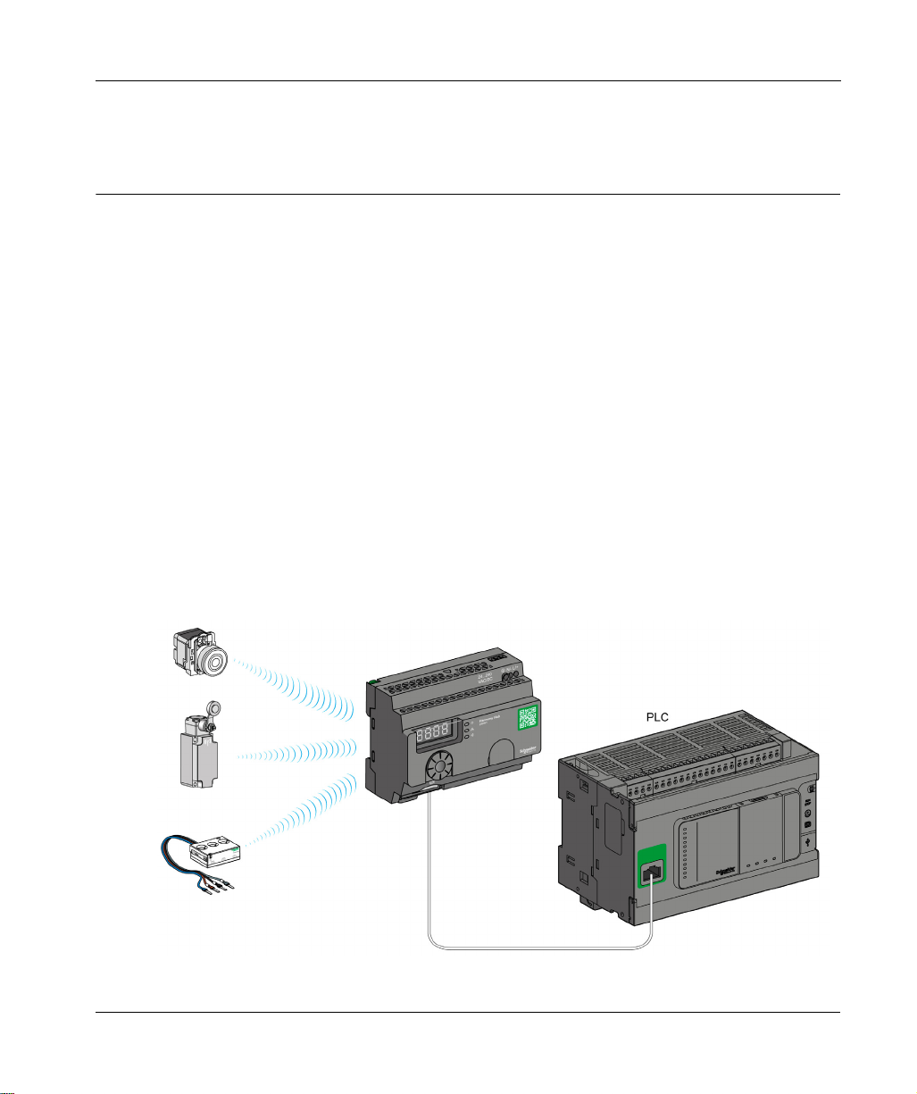
Basic Architecture with PLC
The following figure shows the transmission between three transmitters and a ZBRN1
Harmony Hub:
NOTE: You can associate 1 Harmony Hub with up to 60 transmitters. Each transmitter has a
unique ID (for example, 030079B1).
EIO0000001177 03/2019 11
Introduction
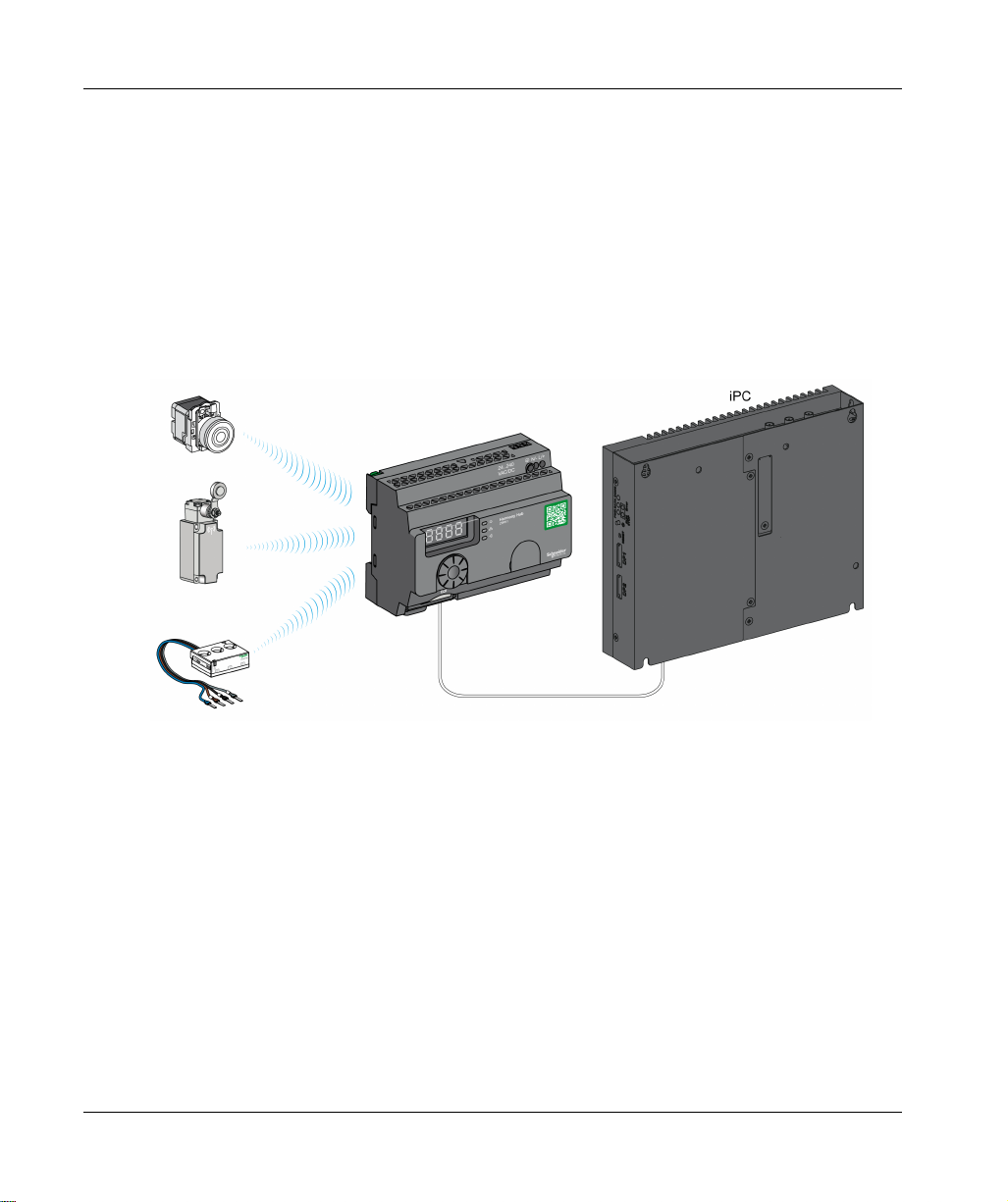
IT/OT Architecture
Harmony Hub provides network connectivity openness by operating as intermediate equipment
between the wireless devices and PLCs (Programmable Logic Controller) or all industrial PCs
(IT/OT box) that support Modbus TCP protocols.
Harmony Hub is providing an easy way to digitalize your production line to improve operation
efficiency (OEE) by using a non-intrusive wireless system easy to connect to your IT system.
Harmony Hub collect physical signals from an operator interface or secondary sensing to generate
computed data information for CMMS tools and operation management tools.
Data can be analyzed through our dedicated EcoStruxure platform through AVEVA Software,
Maintenace Advisor software, and Augmented Operator Advisor application.
12
For details, refer to IT/OT Architecture
(seepage179)
.
EIO0000001177 03/2019

Compatible Transmitters
Harmony Hub is compatible with:
The Harmony battery-less and wireless pushbuttons offer based on radio technology
The Harmony battery-less and wireless rope pull switch
The OsiSense battery-less and wireless radio limit switches
Temperature sensors with battery
Energy sensors
The following figures show some examples of transmitters:
Example 1: pushbutton with a plastic head
Example 2: pushbutton with a metal head
Introduction
Example 3: pushbutton with a plastic head enclosed in a handy box
EIO0000001177 03/2019 13
Introduction
Product References
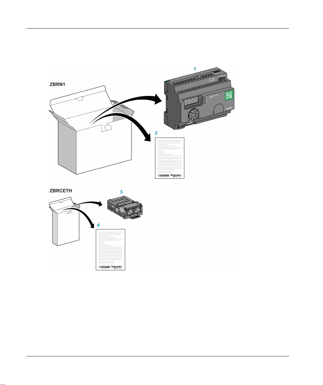
ZBRN1: Standard Harmony Hub with Communication Module
14
1 Harmony Hub
2 Instruction Sheet (ZBRN1)
3 Modbus TCP Communication module
4 Instruction Sheet (ZBRCETH)
NOTE: ZBRN1 must be associated with a communication module, reference ZBRCETH (Ethernet
protocol).
EIO0000001177 03/2019

ZBRN2: Harmony Hub for Modbus Serial Line Communication
1 Harmony Hub
2 Instruction Sheet
Introduction
Difference Between ZBRN1 and ZBRN2
ZBRN2 has an embedded communication port for a Modbus serial line, whereas ZBRN1 can
support different protocols using a communication module.
EIO0000001177 03/2019 15

Introduction
16
EIO0000001177 03/2019

Harmony XB5R
Physical Description
EIO0000001177 03/2019
Physical Description
Chapter 2
Physical Description
Purpose
This chapter provides an overview of the Harmony XB5R ZBRN1 and ZBRN2 hardware:
description, output connectors, installation, and power supply connections.
What Is in This Chapter?
This chapter contains the following sections:
Section Topic Page
2.1 Product Overview 18
2.2 Installation 20
2.3 Specifications 33
2.4 Data Management 36
EIO0000001177 03/2019 17
Physical Description
Product Overview
Section 2.1
Product Overview
Hardware Description
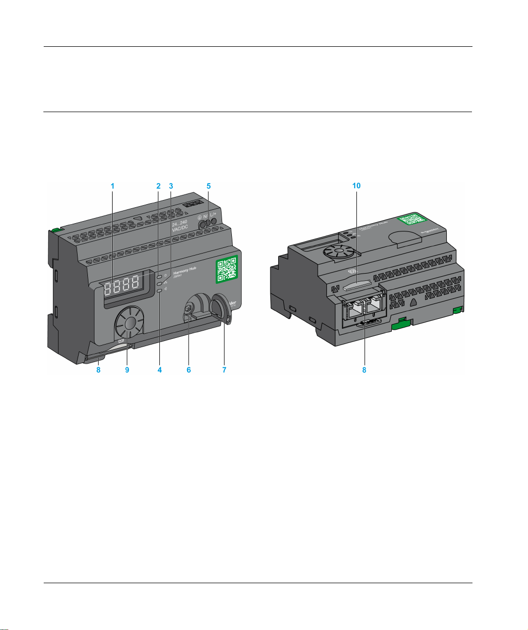
ZBRN1
18
1 Four 7-segments displays with 5 LEDs
2 Power LED
3 Communication LED
4 Radio signal strength LED
5 Power input terminal block
6 Connector for the optional external antenna
7 Protective plug for the connector for the optional external antenna
8 ZBRCETH Communication module inserted with 2 RJ45 Ethernet connectors
9 Jog dial
10 SD memory card slot
EIO0000001177 03/2019
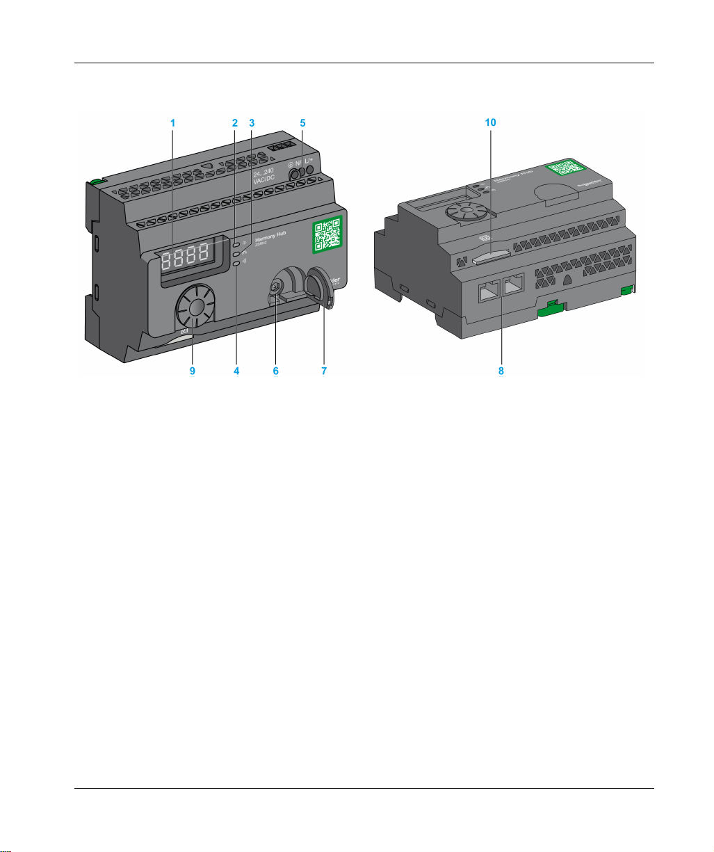
ZBRN2
Physical Description
1 Four 7-segments displays with 5 LEDs
2 Power LED
3 Communication LED
4 Radio signal strength LED
5 Power input terminal block
6 Connector for the optional external antenna
7 Protective plug for the connector for the optional external antenna
8 2 RS-485 Modbus serial line connectors
9 Jog dial
10 SD memory card slot
EIO0000001177 03/2019 19

Physical Description
Installation
Section 2.2
Installation
What Is in This Section?
This section contains the following topics:
Installation Requirements 21
Mechanical Installation 28
Environmental Features 30
Housing 32
Topic Page
20
EIO0000001177 03/2019
Installation Requirements
Before Starting
Read and understand this chapter before beginning the installation of your Harmony Hub.
HAZARD OF ELECTRIC SHOCK, EXPLOSION OR ARC FLASH
Disconnect all power from all equipment including connected devices prior to removing any
covers or doors, or installing or removing any accessories, hardware, cables, or wires except
under the specific conditions specified in the appropriate hardware guide for this equipment.
Always use a properly rated voltage sensing device to confirm the power off where and when
indicated.
Replace and secure all covers, accessories, hardware, cables, and wires and confirm that a
proper ground connection exists before applying power to the equipment.
Use only the specified voltage when operating this equipment and any associated products.
Failure to follow these instructions will result in death or serious injury.
Operating Environment
UNINTENDED EQUIPMENT OPERATION
Install and operate this equipment according to the environmental conditions described in the
operating limits.
Failure to follow these instructions can result in death, serious injury, or equipment damage.
Physical Description
DANGER
WARNING
EIO0000001177 03/2019 21

Physical Description
Installation Considerations
UNINTENDED EQUIPMENT OPERATION
Use appropriate safety interlocks where personnel and/or equipment hazards exist.
Install and operate this equipment in an enclosure appropriately rated for its intended
environment.
Do not use this equipment in safety critical and hoisting machine functions due to:
No permanent communication
No acknowledge of the message from the receiver to the transmitters.
Do not disassemble, repair, or modify this equipment.
Do not connect any wiring to reserved, unused connections, or to connections designated as
not connected (N.C.).
Failure to follow these instructions can result in death, serious injury, or equipment damage.
WARNING
22
EIO0000001177 03/2019

Architecture
The following figure shows the general principle of Harmony Hub architecture:
Physical Description
EIO0000001177 03/2019 23

Physical Description
NOTE:
The previous figure is not exhaustive. It shows only the general principle of the architecture.
Refer to the specifications section
Harmony Hubs.
Refer to the user manual of your associated products for detailed wiring diagrams and
instructions.
Harmony Hub can be connected to any PLC supporting the network buses listed in this
document.
Connection Requirements
Power Supply Connection
24...240 Vac/Vdc
Network connection
RS-485 Modbus serial line network
Ethernet Modbus TCP network
(see page 33)
for detailed wiring diagram and instructions for
24
EIO0000001177 03/2019
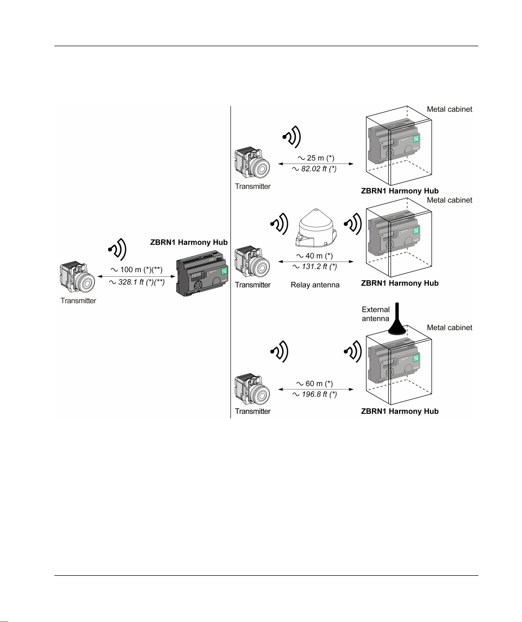
Maximum Distances
The following figure shows the maximum distance between the transmitters and the ZBRN1
Harmony Hubs:
Physical Description
(*) The application environment can modify the typical values.
(**) Free field (unobstructed and without electromagnetic perturbations).
EIO0000001177 03/2019 25
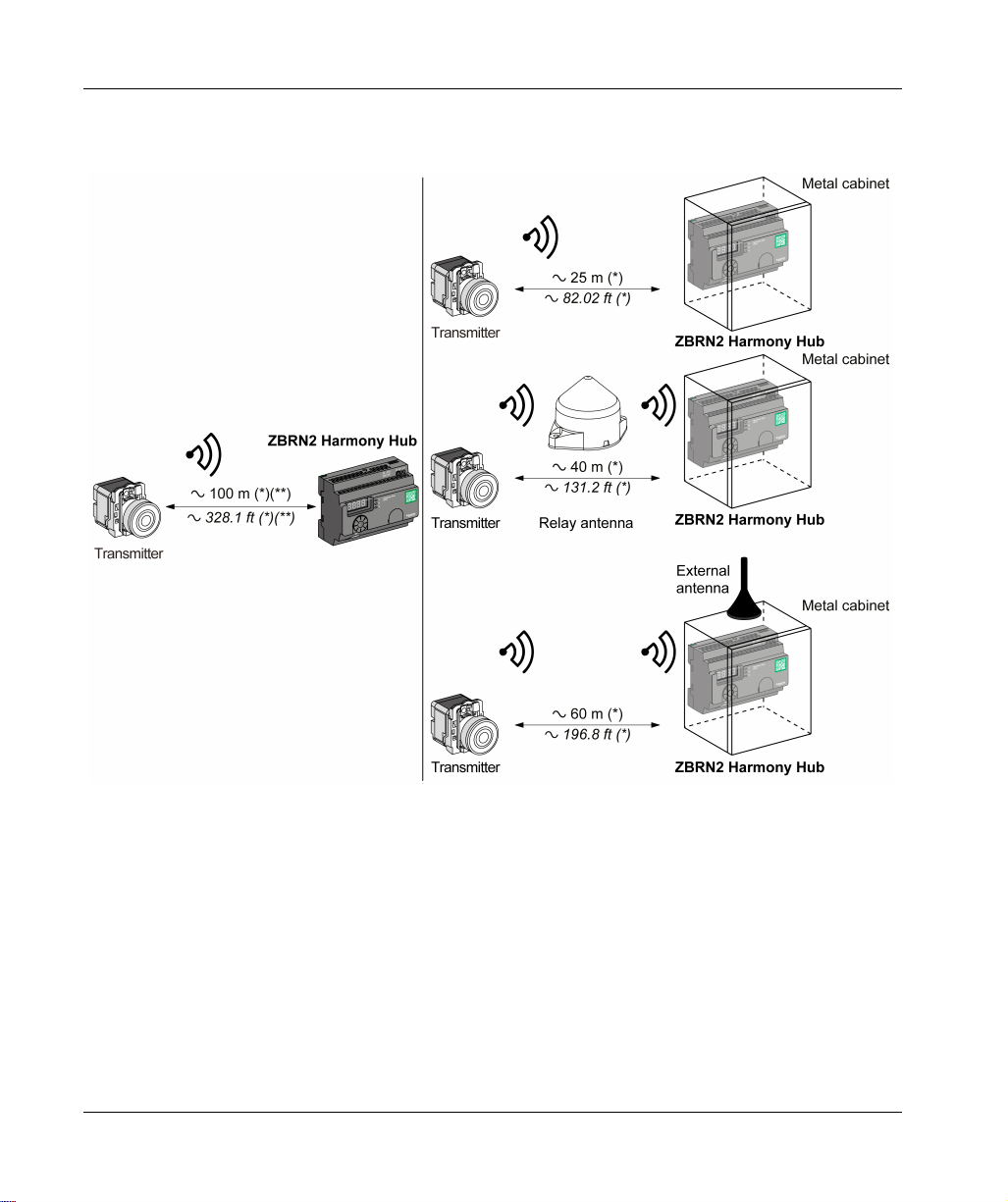
Physical Description
The following figure shows the maximum distance between the transmitters and the ZBRN2
Harmony Hubs:
26
(*) The application environment can modify the typical values.
(**) Free field (unobstructed and without electromagnetic perturbations).
EIO0000001177 03/2019

Physical Description
The level of signal attenuation depends on the material through which the signal passes:
Material Attenuation
Glass window
Plaster wall
Brick wall
Concrete wall
Metal structure
(*) Values for indication purpose only. Actual values depend on the thickness and nature of
the material.
10...20 %
30...45 %
60 %
70...80 %
60...100 %
(*)
(*)
(*)
(*)
(*)
NOTE: You can add ZBRA1 or ZBRA2 antenna or both to increase the range. The reception is
reduced if Harmony Hub is placed in a metal cabinet.
For further information on the use of ZBRA1 and ZBRA2 antennas, refer to the Radio chapter
(seepage99)
.
Impact of the radio performances in the environment:
For any environment, the radio performances are subjected to be instable due to perturbations
made by any kind of industrial machines, processes, or electronic devices.
As a consequence at any time, it is possible that the radio frames sent by a transmitter will not
be caught by the receiver during the perturbation.
With Harmony XB5R offer, only one radio frame is sent to the receiver, there is no permanent
radio communication. This reason prevents the use of Harmony XB5R offer for applications
where permanent reliability and/or permanent precisions are needed.
EIO0000001177 03/2019 27

Physical Description
Mechanical Installation
Mounted on DIN Rail
Harmony Hub must be installed on DIN rails complying with EN/IEC 60715.
To install Harmony Hub, use a tool to press down the D lock for inserting the DIN rail.
The following figure shows the position of Harmony Hub on the DIN rail:
28
EIO0000001177 03/2019

Mounted on a Grid or Plate
Harmony Hub can be installed on a grid or a plate.
The following steps explain how to install the module:
Step Action
1 Pull out the panel mounting hooks.
2 Mount Harmony Hub on the grid or plate using the screws as shown in the
following figure.
Physical Description
EIO0000001177 03/2019 29

Physical Description
Environmental Features
Specifications
The following table shows the general environmental specifications:
Characteristics Specifications
Standards Conformity to
standards
Conformity to
standards
Conformity to
standards
Radio
certifications
Agencies
UL USA UL508, 17th edition
CSA Canada CSA C22.2, No. 142-M2000
C-Tick Australia –
GOST Russia –
ANATEL Brazil –
FCC USA –
SRRC China –
CCC China –
MIC Japan –
RSS Canada –
Ambient operating
temperature
Storage temperature –40...+70 °C (–40...+158 °F)
Relative humidity 95% RH at 55 °C (131 °F)
Degree of pollution 2 (IEC60664-1)
Degree of protection IP20
Shock resistance Half sine wave acceleration: 11 ms 30 gn (IEC 60068-2 27)
Resistance to vibration ±3.5 mm (±0.13 in.): 5...8.14 Hz
R&TTE 1999/5/EC, LVD 2006/95/EC, EMC2004/108/EC
EN/IEC 60947-1, EN/IEC 60947-5-1, EN/IEC60950-1, IEC61131-2, EN
300440-2, EN300489-3, EN300328, EN62311
UL 508 (USA), CSA C22-2 n° 14 (Canada), CCC (China), Gost (Russia)
FCC (USA), CSA, RSS (Canada), C-Tick (Australia), ANATEL (Brazil),
SRRC (China), MIC (Japan)
–25...+55 °C (–13...+131 °F)
1 gn: 8.14...150 Hz when mounted on a panel
2 gn: 8.45...150 Hz when mounted on a DIN rail (IEC 60068-2-6)
30
EIO0000001177 03/2019
 Loading...