


 Loading...
Model AP-P3
Machine Code: M124/M125
Field Service Manual
14 September, 2012
Subject to change

Important Safety Notices
Prevention of Physical Injury
1.Before disassembling or assembling parts of the machine and peripherals, make sure that the machine power cord is unplugged.
2.The wall outlet should be near the machine and easily accessible.
3.If any adjustment or operation check has to be made with exterior covers off or open while the main switch is turned on, keep hands away from electrified or mechanically driven components.
4.The machine drives some of its components when it completes the warm-up period. Be careful to keep hands away from the mechanical and electrical components as the machine starts operation.
5.The inside and the metal parts of the fusing unit become extremely hot while the machine is operating. Be careful to avoid touching those components with your bare hands.
Health Safety Conditions
1.Toner and developer are non-toxic, but if you get either of them in your eyes by accident, it may cause temporary eye discomfort. Immediately wash eyes with plenty of water. If unsuccessful, get medical attention.
2.The machine, which use high voltage power source, can generate ozone gas. High ozone density is harmful to human health. Therefore, the machine must be installed in a well-ventilated room.
Observance of Electrical Safety Standards
The machine and its peripherals must be serviced by a customer service representative who has completed the training course on those models.
• Keep the machine away from flammable liquids, gases, and aerosols. A fire or an explosion might occur.
•The Controller board on this machine contains a lithium battery. The danger of explosion exists if a battery of this type is incorrectly replaced. Replace only with the same or an equivalent type recommended by the manufacturer. Discard batteries in accordance with the manufacturer's instructions and local regulations.
•The optional fax and memory expansion units contain lithium batteries, which can explode if replaced incorrectly. Replace only with the same or an equivalent type recommended by the
1

manufacturer. Do not recharge or burn the batteries. Used batteries must be handled in accordance with local regulations.
Safety and Ecological Notes for Disposal
1.Do not incinerate toner bottles or used toner. Toner dust may ignite suddenly when exposed to an open flame.
2.Dispose of used toner, the maintenance unit which includes developer or the organic photoconductor in accordance with local regulations. (These are non-toxic supplies.)
3.Dispose of replaced parts in accordance with local regulations.
4.When keeping used lithium batteries in order to dispose of them later, do not put more than 100 batteries per sealed box. Storing larger numbers or not sealing them apart may lead to chemical reactions and heat build-up.
Laser Safety
The Center for Devices and Radiological Health (CDRH) prohibits the repair of laser-based optical units in the field. The optical housing unit can only be repaired in a factory or at a location with the requisite equipment. The laser subsystem is replaceable in the field by a qualified Customer Engineer. The laser chassis is not repairable in the field. Customer engineers are therefore directed to return all chassis and laser subsystems to the factory or service depot when replacement of the optical subsystem is required.
•Use of controls, or adjustment, or performance of procedures other than those specified in this manual may result in hazardous radiation exposure.
•WARNING: Turn off the main switch before attempting any of the procedures in the Laser Optics Housing Unit section. Laser beams can seriously damage your eyes.
•CAUTION MARKING:
2

The Aim of Anti-tip Components and Precautions
The anti-tip components are necessary for meeting the requirements of IEC60950-1, the international standard for safety.
The aim of these components is to prevent the products, which are heavy in weight, from toppling as a result of people running into or leaning onto the products, which can lead to serious accidents such as persons becoming trapped under the product. (U.S.: UL60950-1, Europe: EN60950-1)
Therefore, removal of such components must always be with the consent of the customer. Do not remove them at your own judgment.
Warnings, Cautions, Notes
In this manual, the following important symbols and notations are used.
•A Warning indicates a potentially hazardous situation. Failure to obey a Warning could result in death or serious injury.
•A Caution indicates a potentially hazardous situation. Failure to obey a Caution could result in minor or moderate injury or damage to the machine or other property.
•Obey these guidelines to avoid problems such as misfeeds, damage to originals, loss of valuable data and to prevent damage to the machine.
•This information provides tips and advice about how to best service the machine.
3
Symbols, Abbreviations and Trademarks
This manual uses several symbols and abbreviations. The meaning of those symbols and abbreviations are as follows:
|
See or Refer to |
|
|
|
Clip ring |
|
|
|
Screw |
|
|
|
Connector |
|
|
|
Clamp |
|
|
|
E-ring |
|
|
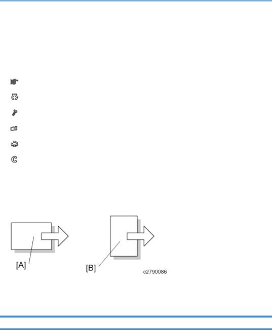
SEF |
Short Edge Feed |
|
|
LEF |
Long Edge Feed |
|
|
[A]Short Edge Feed (SEF)
[B]Long Edge Feed (LEF)
Trademarks
Microsoft®, Windows®, and MS-DOS® are registered trademarks of Microsoft Corporation in the United States and /or other countries.
PostScript® is a registered trademark of Adobe Systems, Incorporated. PCL® is a registered trademark of Hewlett-Packard Company. Ethernet® is a registered trademark of Xerox Corporation.
PowerPC® is a registered trademark of International Business Machines Corporation.
4

Other product names used herein are for identification purposes only and may be trademarks of their respective companies. We disclaim any and all rights involved with those marks.
5

TABLE OF CONTENTS |
|
Important Safety Notices................................................................................................................................... |
1 |
Prevention of Physical Injury.......................................................................................................................... |
1 |
Health Safety Conditions............................................................................................................................... |
1 |
Observance of Electrical Safety Standards................................................................................................. |
1 |
Safety and Ecological Notes for Disposal................................................................................................... |
2 |
Laser Safety..................................................................................................................................................... |
2 |
The Aim of Anti-tip Components and Precautions....................................................................................... |
3 |
Warnings, Cautions, Notes........................................................................................................................... |
3 |
Symbols, Abbreviations and Trademarks......................................................................................................... |
4 |
Trademarks..................................................................................................................................................... |
4 |
1. Product Information |
|
Specifications.................................................................................................................................................... |
19 |
Product Overview............................................................................................................................................. |
20 |
Component Layout....................................................................................................................................... |
20 |
Paper Path.................................................................................................................................................... |
21 |
Drive Layout.................................................................................................................................................. |
22 |
Machine Codes and Peripherals Configuration............................................................................................ |
24 |
Guidance for Those Who are Familiar with Predecessor Products.............................................................. |
27 |
2. Installation |
|
Installation Requirements................................................................................................................................. |
29 |
Environment.................................................................................................................................................. |
29 |
Machine Level.............................................................................................................................................. |
30 |
Machine Space Requirements.................................................................................................................... |
30 |
Power Requirements.................................................................................................................................... |
31 |
Printer Installation............................................................................................................................................. |
32 |
Power Socket for Peripherals...................................................................................................................... |
32 |
Installation Flow Chart................................................................................................................................. |
32 |
Installation Procedure.................................................................................................................................. |
34 |
Unpacking........................................................................................................................................... |
34 |
Installing the Toner.............................................................................................................................. |
38 |
Loading Paper..................................................................................................................................... |
39 |
Turning Power On............................................................................................................................... |
41 |
Selecting the Panel Display Language.............................................................................................. |
42 |
6

Printing the Test Page.......................................................................................................................... |
43 |
Settings Relevant to the Service Contract.......................................................................................... |
43 |
Settings for @Remote Service (Embedded RC Gate)....................................................................... |
44 |
Meter Click Charge..................................................................................................................................... |
47 |
External USB Keyboard (External Option)................................................................................................ |
50 |
Moving the Machine................................................................................................................................... |
51 |
Transporting the Machine........................................................................................................................... |
52 |
Optional Unit Combinations............................................................................................................................ |
53 |
Machine Options......................................................................................................................................... |
53 |
Controller Options....................................................................................................................................... |
53 |
1200 LCT (D631)............................................................................................................................................ |
55 |
Component Check....................................................................................................................................... |
55 |
Installation Procedure.................................................................................................................................. |
56 |
Side Fence Position Change....................................................................................................................... |
58 |
Bridge Unit (D634).......................................................................................................................................... |
60 |
Component Check....................................................................................................................................... |
60 |
Installation Procedure.................................................................................................................................. |
60 |
2000-sheet booklet finisher (D637) /3000-sheet finisher (D636)............................................................ |
64 |
Accessory Check.......................................................................................................................................... |
64 |
Installation Procedure.................................................................................................................................. |
65 |
Support Tray Installation..................................................................................................................... |
70 |
Punch Unit (D570)........................................................................................................................................... |
71 |
Component Check....................................................................................................................................... |
71 |
Installation Procedure.................................................................................................................................. |
72 |
Output Jogger Unit (B703)............................................................................................................................. |
77 |
Accessories................................................................................................................................................... |
77 |
Installation.................................................................................................................................................... |
77 |
Mail Bin (M413).............................................................................................................................................. |
80 |
Component Check....................................................................................................................................... |
80 |
Installation Procedure.................................................................................................................................. |
81 |
Anti-Condensation Heater............................................................................................................................... |
88 |
Component Check....................................................................................................................................... |
88 |
Installation Procedure.................................................................................................................................. |
89 |
7

For installing the tray heater in the main machine |
............................................................................89 |
For installing the tray heater in D580................................................................................................ |
90 |
For Installing the tray heater in D581................................................................................................ |
92 |
Controller Options............................................................................................................................................ |
96 |
Overview...................................................................................................................................................... |
96 |
I/F Card Slots...................................................................................................................................... |
96 |
SD Card Slots...................................................................................................................................... |
96 |
SD Card Appli Move................................................................................................................................... |
97 |
Overview............................................................................................................................................. |
97 |
Move Exec........................................................................................................................................... |
98 |
Undo Exec........................................................................................................................................... |
98 |
3. Preventive Maintenance |
|
Maintenance Items........................................................................................................................................ |
101 |
Touch Screen Calibration............................................................................................................................. |
102 |
4. Replacement and Adjustment |
|
Beforehand..................................................................................................................................................... |
107 |
Special Tools.................................................................................................................................................. |
108 |
Image Adjustment.......................................................................................................................................... |
109 |
Registration................................................................................................................................................ |
109 |
Image Area....................................................................................................................................... |
109 |
Leading Edge.................................................................................................................................... |
109 |
Side to Side....................................................................................................................................... |
109 |
Adjustment Standard........................................................................................................................ |
109 |
Paper Registration Standard............................................................................................................ |
110 |
Adjustment Procedure....................................................................................................................... |
110 |
Erase Margin Adjustment.......................................................................................................................... |
111 |
Color Registration...................................................................................................................................... |
112 |
Line Position Adjustment................................................................................................................... |
112 |
Gamma Correction................................................................................................................................... |
113 |
Summary............................................................................................................................................ |
113 |
Adjustment Procedure....................................................................................................................... |
115 |
Exterior Covers............................................................................................................................................... |
117 |
Front Door.................................................................................................................................................. |
117 |
8
Left Cover................................................................................................................................................... |
118 |
Rear Cover................................................................................................................................................. |
118 |
Top Right and Rear Cover........................................................................................................................ |
119 |
Right Rear Cover....................................................................................................................................... |
119 |
Operation Panel........................................................................................................................................ |
120 |
Paper Exit Cover........................................................................................................................................ |
122 |
Output Tray................................................................................................................................................ |
123 |
Ozone Filter............................................................................................................................................... |
124 |
Ozone filter for the charge unit....................................................................................................... |
124 |
Ozone filter for the AC Controller................................................................................................... |
125 |
Laser Optics.................................................................................................................................................... |
126 |
Caution Decal Location............................................................................................................................ |
126 |
LD Safety Switch........................................................................................................................................ |
127 |
Error Messages................................................................................................................................. |
127 |
Laser Optics Housing Unit........................................................................................................................ |
128 |
Preparing the new laser optics housing unit................................................................................... |
128 |
Before removing the old laser optics housing unit......................................................................... |
129 |
Recovery procedure for no replacement preparation of laser optics housing unit..................... |
129 |
Removing the old laser optics housing unit..................................................................................... |
130 |
Installing a new laser optics housing unit........................................................................................ |
131 |
After installing the new laser optics housing unit............................................................................ |
132 |
Polygon Mirror Motor and Drive Board.................................................................................................. |
133 |
Airflow Fans............................................................................................................................................... |
135 |
Laser Optics Rear Right Thermistor........................................................................................................... |
135 |
Image Creation.............................................................................................................................................. |
137 |
PCDU.......................................................................................................................................................... |
137 |
Drum Unit and Development Unit............................................................................................................ |
138 |
Developer.......................................................................................................................................... |
141 |
Toner Collection Bottle.............................................................................................................................. |
143 |
Second Duct Fans...................................................................................................................................... |
144 |
When reinstalling the second duct fans.......................................................................................... |
145 |
Third Duct Fan............................................................................................................................................ |
145 |
When reinstalling the third duct fan................................................................................................ |
146 |
9

Toner Pump Unit........................................................................................................................................ |
146 |
When installing the new toner pump unit....................................................................................... |
149 |
Toner End Sensor...................................................................................................................................... |
152 |
Image Transfer............................................................................................................................................... |
153 |
Image Transfer Belt Cleaning Unit........................................................................................................... |
153 |
Image Transfer Belt Unit............................................................................................................................ |
153 |
Image Transfer Belt.................................................................................................................................... |
155 |
When reinstalling the image transfer belt....................................................................................... |
159 |
Paper Transfer................................................................................................................................................ |
162 |
Paper Transfer Roller Unit......................................................................................................................... |
162 |
Paper Transfer Unit.................................................................................................................................... |
162 |
ID Sensor Board........................................................................................................................................ |
164 |
Cleaning for ID sensors.................................................................................................................... |
165 |
After installing a new ID sensor unit/board .................................................................................. |
166 |
Temperature and Humidity Sensor.......................................................................................................... |
166 |
Drive Unit........................................................................................................................................................ |
167 |
Gear Unit................................................................................................................................................... |
167 |
When installing the drive unit........................................................................................................... |
174 |
Adjustment after replacing the gear unit......................................................................................... |
174 |
Registration Motor..................................................................................................................................... |
175 |
Paper Feed Motor..................................................................................................................................... |
176 |
Drum/Development Motors for M, C, and Y......................................................................................... |
177 |
Drum/Development Motor-K................................................................................................................... |
178 |
ITB Drive Motor......................................................................................................................................... |
179 |
Fusing/Paper Exit Motor.......................................................................................................................... |
179 |
Image Transfer Belt Contact Motor.......................................................................................................... |
180 |
Duplex Inverter Motor............................................................................................................................... |
180 |
Pressure Roller Contact Motor.................................................................................................................. |
182 |
Duplex/By-pass Motor............................................................................................................................. |
183 |
Paper Transfer Contact Motor.................................................................................................................. |
185 |
Toner Transport Motor.............................................................................................................................. |
187 |
Toner Collection Unit................................................................................................................................. |
188 |
Paper Feed Clutches................................................................................................................................. |
188 |
10

Development Clutch-Y.............................................................................................................................. |
191 |
Development Clutches for M and C........................................................................................................ |
192 |
Development Clutch-K.............................................................................................................................. |
193 |
Fusing.............................................................................................................................................................. |
195 |
Fusing Unit.................................................................................................................................................. |
195 |
Fusing Exit Shutter Plate............................................................................................................................ |
197 |
Fusing Entrance Guide Plate..................................................................................................................... |
197 |
Cleaning Requirement...................................................................................................................... |
199 |
Fusing Exit Guide Plate Cleaning Procedure........................................................................................... |
199 |
Fusing Unit Upper Cover.......................................................................................................................... |
200 |
Fusing Unit Lower Cover........................................................................................................................... |
201 |
Fusing Sleeve Belt Unit.............................................................................................................................. |
202 |
Oil Absorber Felt.............................................................................................................................. |
205 |
Pressure Roller............................................................................................................................................ |
206 |
Stripper Plate............................................................................................................................................. |
208 |
Cleaning Requirement...................................................................................................................... |
209 |
Pressure Roller Thermistors........................................................................................................................ |
209 |
Pressure Roller Thermostats....................................................................................................................... |
210 |
NC Sensors................................................................................................................................................ |
210 |
Fusing Fan.................................................................................................................................................. |
211 |
When installing the fusing fan.......................................................................................................... |
212 |
Paper Exit Fan............................................................................................................................................ |
212 |
When installing the paper exit fan.................................................................................................. |
213 |
AC Controller Board Fan.......................................................................................................................... |
213 |
When installing the AC controller fan............................................................................................. |
214 |
Fusing Entrance Thermopiles.................................................................................................................... |
214 |
When cleaning the lens of the thermopile...................................................................................... |
215 |
Pressure Roller HP Sensor......................................................................................................................... |
215 |
QSU fan..................................................................................................................................................... |
216 |
Fusing Unit Shutter Plate Drive Motor...................................................................................................... |
218 |
Fusing Unit Shutter Plate Home Position Sensor...................................................................................... |
218 |
Fusing Unit Shutter Plate Drive Mechanism............................................................................................. |
219 |
Paper Feed..................................................................................................................................................... |
222 |
11

Paper Feed Unit......................................................................................................................................... |
222 |
Pick-Up, Feed and Separation Rollers..................................................................................................... |
223 |
Tray 1 and Tray 2............................................................................................................................. |
223 |
Tray Lift Motor............................................................................................................................................ |
224 |
Vertical Transport, Paper Overflow, Paper End and Paper Feed Sensor............................................. |
224 |
Registration Sensor.................................................................................................................................... |
225 |
By-pass Paper Size Sensor and By-pass Paper Length Sensor............................................................. |
226 |
When reinstalling the by-pass paper size sensor.......................................................................... |
227 |
By-pass Bottom Tray.................................................................................................................................. |
228 |
By-pass Paper End Sensor........................................................................................................................ |
231 |
By-pass Pick-up, Feed and Separation Roller, Torque Limiter............................................................... |
232 |
By-pass Feed Clutch.................................................................................................................................. |
233 |
Paper Exit Unit........................................................................................................................................... |
234 |
Fusing Exit, Paper Overflow, Junction Paper Jam and Paper Exit Sensor............................................ |
235 |
Duplex Unit..................................................................................................................................................... |
237 |
Duplex Unit................................................................................................................................................ |
237 |
Duplex Door Sensor.................................................................................................................................. |
238 |
Duplex Entrance Sensor............................................................................................................................ |
239 |
Duplex Exit Sensor.................................................................................................................................... |
240 |
Electrical Components................................................................................................................................... |
241 |
Boards........................................................................................................................................................ |
241 |
Controller Box closed....................................................................................................................... |
241 |
Behind the IOB.................................................................................................................................. |
242 |
Controller Box Open........................................................................................................................ |
242 |
Controller Unit........................................................................................................................................... |
243 |
Controller Box Right Cover....................................................................................................................... |
243 |
Controller Box............................................................................................................................................ |
243 |
When opening the controller box................................................................................................... |
243 |
When removing the controller box................................................................................................. |
244 |
IOB (In/Out Board).................................................................................................................................. |
247 |
BB (Bridge Board)..................................................................................................................................... |
248 |
BCU............................................................................................................................................................ |
248 |
When installing the new BCU.......................................................................................................... |
249 |
12

PSU............................................................................................................................................................. |
250 |
PSU bracket....................................................................................................................................... |
250 |
PSU board......................................................................................................................................... |
250 |
PSU fans............................................................................................................................................ |
251 |
Shutdown Switch....................................................................................................................................... |
252 |
ITB Power Supply Board........................................................................................................................... |
253 |
High Voltage Supply Board..................................................................................................................... |
254 |
High Voltage Supply Board Bracket....................................................................................................... |
254 |
AC Controller Board................................................................................................................................. |
255 |
AC Controller Board Bracket................................................................................................................... |
255 |
Controller Board........................................................................................................................................ |
256 |
When installing the new controller board...................................................................................... |
258 |
HDD Fan.................................................................................................................................................... |
258 |
When installing the HDD fan........................................................................................................... |
259 |
HDD............................................................................................................................................................ |
259 |
When installing a new HDD unit..................................................................................................... |
260 |
Toner Bottle Detection Board................................................................................................................... |
260 |
NVRAM Replacement Procedure............................................................................................................ |
261 |
NVRAM on the BCU........................................................................................................................ |
261 |
NVRAM on the controller board..................................................................................................... |
262 |
Tube Cooling Fan (1st Duct Fan)............................................................................................................. |
263 |
Using Dip Switches........................................................................................................................................ |
264 |
Controller Board........................................................................................................................................ |
264 |
BCU Board................................................................................................................................................. |
264 |
5. System Maintenance |
|
Service Program Mode................................................................................................................................. |
265 |
SP Tables.................................................................................................................................................... |
265 |
Enabling and Disabling Service Program Mode.................................................................................... |
265 |
Entering SP Mode............................................................................................................................. |
265 |
Exiting SP Mode............................................................................................................................... |
265 |
Types of SP Modes.................................................................................................................................... |
265 |
SP Mode Button Summary............................................................................................................... |
266 |
Selecting the Program Number....................................................................................................... |
267 |
13

Exiting Service Mode....................................................................................................................... |
268 |
Service Mode Lock/Unlock............................................................................................................ |
268 |
Remarks...................................................................................................................................................... |
268 |
Display on the Control Panel Screen.............................................................................................. |
268 |
Others................................................................................................................................................ |
268 |
Service SP Table............................................................................................................................................ |
270 |
SP1-XXX (Service Mode).......................................................................................................................... |
270 |
Engine SP Tables-1........................................................................................................................................ |
285 |
SP1-XXX (Feed)......................................................................................................................................... |
285 |
Engine SP Tables-2........................................................................................................................................ |
299 |
SP2-XXX (Drum)......................................................................................................................................... |
299 |
Engine SP Tables-3........................................................................................................................................ |
307 |
SP3-XXX (Process)..................................................................................................................................... |
307 |
Engine SP Tables-4........................................................................................................................................ |
327 |
SP5-XXX (Mode)....................................................................................................................................... |
327 |
Engine SP Tables-5........................................................................................................................................ |
382 |
SP6-XXX (Peripherals)............................................................................................................................... |
382 |
Engine SP Tables-6........................................................................................................................................ |
390 |
SP7-XXX (Data Log).................................................................................................................................. |
390 |
Input and Output Check................................................................................................................................ |
440 |
Input Check Table..................................................................................................................................... |
440 |
Printer................................................................................................................................................. |
440 |
Table 1: Paper Height Sensor.......................................................................................................... |
443 |
Table 2: Paper Size Switch (Tray 2)............................................................................................... |
443 |
Table 3: Paper Size (By-pass Table)............................................................................................... |
444 |
[FIN (EUP) INPUT Check] Finisher (D636/ D637)....................................................................... |
445 |
[FIN (JAK) INPUT Check] 4bin Mail Box (M413)........................................................................ |
447 |
Bridge Unit (D634)........................................................................................................................... |
448 |
Two-Tray Paper Feed Unit (D580)/ LCT 2000 (D581)/ LCT 1200 (D631)............................ |
448 |
Output Check Table.................................................................................................................................. |
449 |
Printer................................................................................................................................................. |
449 |
[FIN (EUP) OUTPUT Check] (Booklet) Finisher (D636/D637).................................................... |
455 |
FIN(JAK)OUTPUT Check 4bin Mail Box (M413)......................................................................... |
457 |
14

Bridge Unit (D634)........................................................................................................................... |
457 |
4bin Mail Box (M413).................................................................................................................... |
457 |
Two-Tray Paper Feed Unit (D580)/ LCT 2000 (D581)/ LCT 1200 (D631)............................ |
457 |
Firmware Update........................................................................................................................................... |
459 |
Type of Firmware....................................................................................................................................... |
459 |
Before You Begin....................................................................................................................................... |
460 |
Updating Firmware................................................................................................................................... |
461 |
Preparation........................................................................................................................................ |
461 |
Updating Procedure......................................................................................................................... |
461 |
Error Messages................................................................................................................................. |
462 |
Firmware Update Error..................................................................................................................... |
462 |
Recovery after Power Loss............................................................................................................... |
463 |
Updating the LCDC for the Operation Panel.......................................................................................... |
463 |
Handling Firmware Update Errors........................................................................................................... |
464 |
Error Message Table........................................................................................................................ |
464 |
NVRAM Data Upload/Download.............................................................................................................. |
466 |
Uploading Content of NVRAM to an SD card....................................................................................... |
466 |
Downloading an SD Card to NVRAM.................................................................................................... |
467 |
Address Book Upload/Download.............................................................................................................. |
469 |
Information List........................................................................................................................................... |
469 |
Download.................................................................................................................................................. |
469 |
Upload....................................................................................................................................................... |
470 |
Using the Debug Log..................................................................................................................................... |
471 |
Overview.................................................................................................................................................... |
471 |
Switching ON and Setting UP Save Debug Log..................................................................................... |
471 |
Retrieving the Debug Log from the HDD................................................................................................. |
475 |
Debug Log Codes..................................................................................................................................... |
476 |
SP5857-015 Copy SD Card-to-SD Card: Any Desired Key....................................................... |
476 |
SP5857-016 Create a File on HDD to Store a Log...................................................................... |
476 |
SP5857-017 Create a File on SD Card to Store a Log................................................................ |
476 |
Card Save Function....................................................................................................................................... |
477 |
Overview.................................................................................................................................................... |
477 |
Card Save:........................................................................................................................................ |
477 |
15

Procedure................................................................................................................................................... |
477 |
Error Messages.......................................................................................................................................... |
481 |
SMC List Card Save Function....................................................................................................................... |
482 |
Overview.................................................................................................................................................... |
482 |
SMC List Card Save......................................................................................................................... |
482 |
Procedure................................................................................................................................................... |
482 |
File Names of the Saved SMC Lists......................................................................................................... |
484 |
Error Messages.......................................................................................................................................... |
485 |
6. Troubleshooting |
|
Service Call.................................................................................................................................................... |
487 |
Service Call Conditions............................................................................................................................. |
487 |
SC Code Classification.................................................................................................................... |
488 |
SC Table......................................................................................................................................................... |
491 |
Service Call Tables - 1.............................................................................................................................. |
491 |
SC1xx: Scanning.............................................................................................................................. |
491 |
Service Call Tables - 2.............................................................................................................................. |
491 |
SC 2xx: Exposure............................................................................................................................. |
491 |
Service Call Tables - 3.............................................................................................................................. |
498 |
SC3xx: Image Processing – 1......................................................................................................... |
498 |
SC3xx: Image Processing – 2......................................................................................................... |
499 |
Service Call Tables - 4.............................................................................................................................. |
503 |
SC4xx: Image Processing - 3.......................................................................................................... |
503 |
Service Call Tables - 5.............................................................................................................................. |
509 |
SC5xx: Paper Feed and Fusing....................................................................................................... |
509 |
Service Call Tables - 6.............................................................................................................................. |
529 |
SC6xx: Device Communication....................................................................................................... |
529 |
Service Call Tables - 7.............................................................................................................................. |
543 |
SC7xx: Peripherals........................................................................................................................... |
543 |
Service Call Tables - 8.............................................................................................................................. |
553 |
SC8xx: Overall System.................................................................................................................... |
553 |
Service Call Tables - 9.............................................................................................................................. |
569 |
SC9xx: Miscellaneous..................................................................................................................... |
569 |
Process Control Error Conditions.................................................................................................................. |
577 |
16

Developer Initialization Result.................................................................................................................. |
577 |
Process Control Self-Check Result............................................................................................................ |
578 |
Vsg Adjustment Result....................................................................................................................... |
580 |
Line Position Adjustment Result................................................................................................................. |
580 |
Troubleshooting Guide.................................................................................................................................. |
582 |
Image Quality............................................................................................................................................ |
582 |
Line Position Adjustment............................................................................................................................ |
584 |
Test..................................................................................................................................................... |
585 |
Countermeasure list for color registration errors............................................................................ |
585 |
Stain on the Outputs.................................................................................................................................. |
591 |
Problem at Regular Intervals..................................................................................................................... |
592 |
Toner End Recovery Error......................................................................................................................... |
592 |
Flow Chart for the Toner End Recovery Error................................................................................. |
593 |
Toner Bottle Detection Error...................................................................................................................... |
594 |
Solid Image or Halftone Image Error...................................................................................................... |
595 |
Recovery Procedure......................................................................................................................... |
595 |
Problem Prevention Procedure......................................................................................................... |
596 |
Faulty Cleaning.......................................................................................................................................... |
596 |
Black or color lines (2-3mm)........................................................................................................... |
596 |
Band Image Between 20mm and 30mm....................................................................................... |
597 |
Encryption Key Restoration for NVRAM.................................................................................................. |
597 |
How to restore the old encryption key to the machine.................................................................. |
597 |
How to do a forced start up with no encryption key..................................................................... |
598 |
Other Symptoms........................................................................................................................................ |
599 |
Flowchart for the error...................................................................................................................... |
600 |
Countermeasure list for the error..................................................................................................... |
600 |
Jam Detection................................................................................................................................................. |
603 |
Paper Jam Display..................................................................................................................................... |
603 |
Jam Codes and Display Codes................................................................................................................ |
603 |
Paper Size Code............................................................................................................................... |
608 |
Sensor Locations............................................................................................................................... |
610 |
Electrical Component Defects....................................................................................................................... |
611 |
Sensors....................................................................................................................................................... |
611 |
17

Blown Fuse Conditions.............................................................................................................................. |
616 |
Power Supply Unit............................................................................................................................ |
616 |
AC Drive Board................................................................................................................................ |
616 |
7. Energy Saving |
|
Energy Save................................................................................................................................................... |
619 |
Energy Saver Modes................................................................................................................................ |
619 |
Timer Settings.................................................................................................................................... |
619 |
Return to Stand-by Mode................................................................................................................. |
620 |
Recommendation.............................................................................................................................. |
620 |
Energy Save Effectiveness........................................................................................................................ |
620 |
Paper Save..................................................................................................................................................... |
622 |
Effectiveness of Duplex/Combine Function............................................................................................ |
622 |
1. Duplex:.......................................................................................................................................... |
622 |
2. Combine mode:............................................................................................................................ |
622 |
3. Duplex + Combine:...................................................................................................................... |
623 |
How to calculate the paper reduction ratio .................................................................................. |
623 |
18
1. Product Information
Specifications
See "Appendices" for the following information:
•General Specifications
•Supported Paper Sizes
•Software Accessories
•Optional Equipment
19

1. Product Information
Product Overview
Component Layout
1. |
Paper exit rollers |
9. Toner collection bottle |
|
2. |
Duplex unit |
10. |
Laser optics housing unit |
3. |
Fusing unit |
11. |
PCDU (4 colors) |
4. |
Paper transfer roller |
12. |
Image transfer belt cleaning unit |
5. |
Registration roller |
13. |
Image transfer belt unit |
6. |
By-pass feed table |
14. |
Toner bottle (4 colors) |
7. |
Tray 2 |
15. |
ID sensor |
8. |
Tray 1 |
16. |
Fusing sleeve belt unit |
|
|
|
|
20
Product Overview
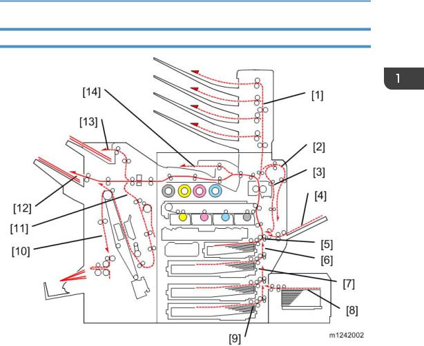
Paper Path
1. |
Mail bin |
8. |
Tray 5: Optional LCT 1200 |
|
2. |
Duplex inverter |
9. |
Tray 4: Optional paper feed unit |
|
3. |
Duplex feed |
10. |
Finisher booklet stapler (Optional) |
|
4. |
By-pass tray feed |
11. |
Finisher stapler (Optional) |
|
5. |
Tray 1 feed |
12. |
Finisher upper tray (Optional) |
|
6. |
Tray 2 feed |
13. |
Finisher proof tray (Optional) |
|
7. |
Tray 3: Optional paper feed unit/LCT |
14. |
Output tray |
|
|
|
|
|
|
The 2000/3000-sheet (booklet) finisher requires the bridge unit and one from the two-tray paper feed unit or the LCT.
21

1. Product Information
Drive Layout
1. |
Toner supply clutch-K and -CMY: |
Turns on/off the drive power to the toner supply unit (K and - |
|
CMY). |
|||
|
|
||
|
|
|
|
2. |
ITB (Image Transfer Belt) contact |
Moves the ITB into contact and away from the color PCDUs. |
|
motor: |
|||
|
|||
|
|
|
|
|
|
Drives the toner attraction pumps and the toner collection coils |
|
3. |
Toner transport motor: |
from the PCDUs, from the transfer belt unit, and inside the |
|
|
|
toner collection bottle. Also rotates the toner bottles. |
|
|
|
|
|
4. |
Development clutch (K, Y, M, C): |
Turns on/off the drive power to the development unit (K, Y, |
|
M, C). |
|||
|
|
||
|
|
|
|
5. |
Drum/Development drive motor |
Drives the color drum unit and development unit (K, Y, M, C). |
|
(K, Y, M, C): |
|||
|
|||
|
|
|
|
6. |
Paper feed clutch: |
Switches the drive power between tray 1 and tray 2. |
|
|
|
|
|
7. |
Paper feed motor: |
Drives the paper feed mechanisms (tray 1/tray 2). |
|
|
|
|
|
22

Product Overview
8. By-pass feed clutch: |
Turns on/off the drive power to the by-pass pick-up, feed and |
||
separation rollers. |
|||
|
|
||
|
|
||
9. Registration motor: |
Drives the registration roller. |
||
|
|
|
|
10. |
By-pass/duplex feed motor: |
Drives the by-pass pick-up, feed and separation roller, and |
|
duplex transport rollers. |
|||
|
|
||
|
|
|
|
11. |
Paper transfer contact motor: |
Moves the paper transfer roller in contact with the image |
|
transfer belt. |
|||
|
|
||
|
|
|
|
12. |
ITB drive motor: |
Drives the image transfer belt unit. |
|
|
|
|
|
13. |
Duplex inverter motor: |
Drives the duplex inverter rollers and duplex transport rollers. |
|
|
|
|
|
14. |
Fusing/paper exit motor: |
Drives the fusing unit and paper exit section. |
|
|
|
|
|
23

1. Product Information
Machine Codes and Peripherals Configuration
Item |
Machine Code |
Call out |
Remarks |
|
|
|
|
|
|
Mainframe |
M124/M125 |
[1] |
- |
|
|
|
|
|
|
Mail bin |
M413 |
[2] |
- |
|
|
|
|
|
|
1200-sheet LCT |
D631 |
[3] |
Requires [4] or [5] |
|
|
|
|
|
|
2000-sheet LCT |
D581 |
[4] |
One from the two |
|
|
|
|
||
Two-tray paper feed unit |
D580 |
[5] |
||
|
||||
|
|
|
|
|
One-tray paper feed unit |
D579 |
[6] |
- |
|
|
|
|
|
|
3000-sheet finisher |
D636 |
[7] |
One from [7] and [8]; |
|
|
|
|
Requires one from [4] and [5] |
|
2000-sheet booklet finisher |
D637 |
[8] |
||
|
|
|
|
|
Punch unit 2/3 holes |
D570-00 (NA) |
- |
Requires [7] or [8] |
|
|
|
|
|
|
Punch unit 2/4 holes |
D570-01 (EU) |
- |
Requires [7] or [8] |
|
|
|
|
|
|
Punch unit 4 holes |
D570-02 |
- |
Requires [7] or [8] |
|
(Scandinavia) |
||||
|
|
|
||
|
|
|
|
|
Bridge unit |
D634 |
[9] |
- |
|
|
|
|
|
24

Machine Codes and Peripherals Configuration
Item |
Machine Code |
Call out |
Remarks |
|
|
|
|
Output jogger unit |
B703 |
- |
Requires [7] |
|
|
|
|
Item |
Machine code |
Call out |
Remark |
|
|
|
|
|
|
PictBridge |
D645-15 |
|
|
|
|
|
|
Those cards should be |
|
IPDS Unit |
M416-24 |
|
||
|
installed from SD slot 2 |
|||
|
|
|
||
SD Card for Netware |
M416-29 |
|
(lower). |
|
|
|
|||
Printing |
[A] |
If multiple applications are |
||
|
||||
|
|
required, merge all |
||
|
D640-21 (NA) |
|
||
|
|
applications in one SD card |
||
|
|
|
||
VM Card |
D640-22 (EU) |
|
with SP mode. ( p.97 "SD |
|
|
Card Appli Move") |
|||
|
|
|
||
|
D640-23 (AA) |
|
||
|
|
|
||
|
|
|
|
|
IEEE 1284 |
B679 |
[B] |
|
|
|
|
|
|
|
|
M344-01 (NA) |
|
You can only install one of |
|
|
|
|
||
Wireless LAN |
M344-02 (EU) |
[C] |
these at a time. |
|
|
||||
|
|
|
|
|
|
M344-08 (EU/AA) |
|
|
|
|
|
|
|
|
Gigabit Ethernet |
M416-30 |
[D] |
- |
|
|
||||
D377 |
||||
|
|
|
||
|
|
|
|
25

1. Product Information
512MB Memory Option |
M354-03 |
[E] |
- |
|
|
|
|||
1GB Memory Option |
M416-27 |
|||
|
|
|||
|
|
|
|
|
HDD*1 (250GB) |
M416-28 |
[F] |
- |
|
|
|
|
|
|
Data Overwrite Security, |
- |
- |
Included in the controller ROM |
|
HDD Encryption |
||||
|
|
|
||
|
|
|
|
*1 The hard disk (M416-28) is supplied with the M125 model as standard equipment.
26

Guidance for Those Who are Familiar with Predecessor Products
Guidance for Those Who are Familiar with Predecessor Products
Machines M124/M125 are successor models to Machines G188/G189. If you have experience with the predecessor products, the following information will be of help when you read this manual.
Different Points from Predecessor Products
Item |
M124/M125 |
G188/G189 |
|
|
|
|
|
Controller Type |
GW+ Controller |
GW Controller |
|
|
|
|
|
New Fusing Unit without the |
Yes |
No |
|
Decurler |
|||
|
|
||
|
|
|
|
Fusing Unit |
NEW QSU-DH fusing system |
IH roller fusing system |
|
|
|
|
|
SMC data |
SD card download or printing |
Printing only |
|
|
|
|
|
Operation Panel |
Tiltable Operation Panel |
Stationary Operation Panel |
|
|
Includes USB/SD slot |
||
|
|
||
|
|
|
|
USB2.0/SD Slot |
Standard |
Optional |
|
|
|
|
|
Data Overwrite Security, |
Included in the controller ROM |
SD card |
|
HDD Encryption |
|||
|
|
||
|
|
|
27

1. Product Information
28
Loading...