


 Loading...
Model SKS-C1
Machine Code: D108
Field Service Manual
6 August, 2010

Safety Notice
Important Safety Notices
Prevention of Physical Injury
1.Be sure that the power cord is unplugged before disassembling or assembling parts of the copier or peripherals.
2.The wall outlet should be near the copier and easily accessible.
3.Note that electrical voltage is supplied to some components of the copier and the paper tray unit even while the main power switch is off.
4.If you start a job before the copier completes the warm-up or initializing period, keep hands away from the mechanical and electrical components until job execution has started. The copier will start making copies as soon as warm-up or initialization is finished.
5.The inside and the metal parts of the fusing unit become extremely hot while the copier is operating. Be careful to avoid touching those components with your bare hands.
Health Safety Conditions
Toner and developer are nontoxic, but getting either of these into your eyes may cause temporary eye discomfort. Try to remove with eye drops or flush with water. If material remains in eye or if discomfort continues, get medical attention.
Observance of Electrical Safety Standards
The copier and its peripherals must be installed and maintained by a customer service representative who has completed the training course on those relevant models.
• Keep the machine away from flammable liquids, gases, and aerosols. A fire or an explosion might occur if this precaution is not observed.
Safe and Ecological Disposal
1.Do not incinerate toner bottles or used toner. Toner dust may ignite suddenly if exposed to an open flame.
2.Dispose of used toner, developer, and organic photoconductors in accordance with local regulations. (These are nontoxic supplies.)
1
3. Dispose of replaced parts in accordance with local regulations.
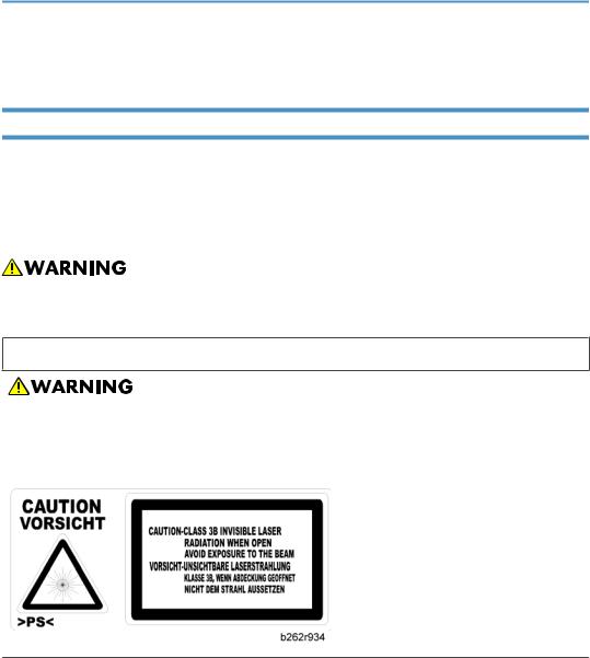
Laser Safety
The Center for Devices and Radiological Health (CDRH) prohibits the repair of laser-based optical units in the field. The optical housing unit can only be repaired in a factory or at a location with the requisite equipment. The laser subsystem is replaceable in the field by a qualified Customer Engineer. The laser chassis is not repairable in the field. Customer engineers are therefore directed to return all chassis and laser subsystems to the factory or service depot when replacement of the optical subsystem is required.
•Use of controls not specified in this manual, or performance of adjustments or procedures not specified in this manual, may result in hazardous radiation exposure.
WARNING FOR LASER UNIT
•Turn off the main switch before attempting any of the procedures in the Laser Unit section. Laser beams can seriously damage your eyes.
CAUTION MARKING:
2
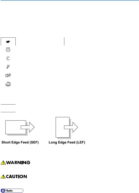
Symbols and Abbreviations
This manual uses several symbols and abbreviations. The meaning of those symbols and abbreviations is as follows:
|
See or Refer to |
|
|
|
Clip ring |
|
|
|
E-ring |
|
|
|
Screw |
|
|
|
Connector |
|
|
|
Clamp |
|
|
SEF |
Short Edge Feed |
|
|
LEF |
Long Edge Feed |
-Core Technology manual
Cautions, Notes, etc.
The following headings provide special information:
•Failure to obey warning information could result in serious injury or death.
•Obey these guidelines to ensure safe operation and prevent minor injuries.
•This information provides tips and advice about how to best service the machine.
3

TABLE OF CONTENTS |
|
Safety Notice...................................................................................................................................................... |
1 |
Important Safety Notices............................................................................................................................... |
1 |
Laser Safety..................................................................................................................................................... |
2 |
Symbols and Abbreviations............................................................................................................................... |
3 |
1. Product Information |
|
Specifications...................................................................................................................................................... |
9 |
Copier............................................................................................................................................................. |
9 |
Printer............................................................................................................................................................ |
11 |
Scanner......................................................................................................................................................... |
12 |
Option Specifications.................................................................................................................................. |
13 |
Supported Paper Sizes................................................................................................................................ |
14 |
Machine Configuration.................................................................................................................................... |
18 |
Mainframe (D108)...................................................................................................................................... |
18 |
Overview.......................................................................................................................................................... |
19 |
Component Layout....................................................................................................................................... |
19 |
Electrical Components................................................................................................................................. |
21 |
Paper Path.................................................................................................................................................... |
24 |
Drive Layout.................................................................................................................................................. |
25 |
Guidance for Those Who are Familiar with Predecessor Products.............................................................. |
27 |
2. Installation |
|
Installation Cautions......................................................................................................................................... |
29 |
Installation Requirements................................................................................................................................. |
30 |
Environment.................................................................................................................................................. |
30 |
Machine Level.............................................................................................................................................. |
30 |
Minimum Operational Space Requirements............................................................................................. |
31 |
Power Requirements.................................................................................................................................... |
32 |
Copier............................................................................................................................................................... |
33 |
Accessory Check.......................................................................................................................................... |
33 |
Installation Procedure.................................................................................................................................. |
33 |
Paper Tray Unit................................................................................................................................................. |
38 |
Accessory Check.......................................................................................................................................... |
38 |
Installation Procedure.................................................................................................................................. |
38 |
Paper Tray Unit Heater.................................................................................................................................... |
41 |
4

Accessory Check.......................................................................................................................................... |
41 |
Installation Procedure.................................................................................................................................. |
42 |
ARDF (B872).................................................................................................................................................... |
49 |
Accessory Check.......................................................................................................................................... |
49 |
Installation Procedure.................................................................................................................................. |
49 |
Optional Paper Tray Grip Handle.................................................................................................................. |
56 |
Accessories................................................................................................................................................... |
56 |
Installation Procedure.................................................................................................................................. |
57 |
3. Preventive Maintenance |
|
PM Tables......................................................................................................................................................... |
59 |
How to Clear the PM Counter......................................................................................................................... |
61 |
4. Replacement and Adjustment |
|
Precautions........................................................................................................................................................ |
63 |
General......................................................................................................................................................... |
63 |
Halogen-free Cable.................................................................................................................................... |
63 |
Special Tools and Lubricants........................................................................................................................... |
64 |
Exterior Covers and Operation Panel............................................................................................................ |
65 |
Rear Cover................................................................................................................................................... |
65 |
Copy Tray..................................................................................................................................................... |
65 |
Scale Plate.................................................................................................................................................... |
66 |
Operation Panel and Upper Covers.......................................................................................................... |
67 |
Right Door..................................................................................................................................................... |
68 |
Bypass Tray.................................................................................................................................................. |
68 |
Platen Cover Sensor.................................................................................................................................... |
69 |
Scanner Unit..................................................................................................................................................... |
70 |
Exposure Glass............................................................................................................................................ |
70 |
Lens Block..................................................................................................................................................... |
71 |
Exposure Lamp, Lamp Stabilizer Board..................................................................................................... |
71 |
Scanner Motor............................................................................................................................................. |
72 |
Scanner HP Sensor...................................................................................................................................... |
74 |
Scanner Alignment Adjustment................................................................................................................... |
74 |
Fusing................................................................................................................................................................ |
76 |
Fusing Unit.................................................................................................................................................... |
76 |
5

Exit Sensor.................................................................................................................................................... |
77 |
Hot Roller Stripper Pawls............................................................................................................................. |
77 |
Hot Roller and Fusing Lamp........................................................................................................................ |
78 |
Thermoswitches and Thermistor.................................................................................................................. |
80 |
Pressure Roller.............................................................................................................................................. |
81 |
Checking the NIP band............................................................................................................................... |
82 |
PCU and Quenching Lamp............................................................................................................................. |
83 |
PCU............................................................................................................................................................... |
83 |
Quenching Lamp.......................................................................................................................................... |
84 |
Exhaust Fan and Main Motor......................................................................................................................... |
85 |
Exhaust Fan.................................................................................................................................................. |
85 |
Main Motor.................................................................................................................................................. |
86 |
Paper Feed........................................................................................................................................................ |
87 |
Paper Feed Roller and Friction Pad............................................................................................................ |
87 |
Paper End Sensor......................................................................................................................................... |
88 |
Registration Sensor...................................................................................................................................... |
88 |
Bypass Paper End Sensor........................................................................................................................... |
89 |
Bypass Feed Roller...................................................................................................................................... |
90 |
Bypass Feed Clutch and Friction Pad......................................................................................................... |
91 |
Paper Feed and Registration Clutches....................................................................................................... |
92 |
Image Transfer.................................................................................................................................................. |
94 |
Transfer Roller.............................................................................................................................................. |
94 |
ID Sensor and Duplex Roller....................................................................................................................... |
95 |
Discharge Plate............................................................................................................................................ |
96 |
BICU and Controller Board............................................................................................................................. |
97 |
BICU.............................................................................................................................................................. |
97 |
Controller Board.......................................................................................................................................... |
98 |
Other Replacements...................................................................................................................................... |
101 |
Duplex Motor............................................................................................................................................ |
101 |
High-Voltage Power Supply Board......................................................................................................... |
102 |
PSU............................................................................................................................................................. |
103 |
Contact-Release Solenoid........................................................................................................................ |
104 |
Toner Supply Clutch.................................................................................................................................. |
104 |
6

Laser Unit........................................................................................................................................................ |
106 |
Location of the Caution Decal.................................................................................................................. |
106 |
Laser Unit.................................................................................................................................................... |
106 |
LD Unit and Polygon Mirror Motor.......................................................................................................... |
107 |
ARDF............................................................................................................................................................... |
108 |
ARDF........................................................................................................................................................... |
108 |
DF Rear Cover........................................................................................................................................... |
109 |
Original Feed Unit..................................................................................................................................... |
109 |
Separation Roller....................................................................................................................................... |
110 |
DF Drive Board.......................................................................................................................................... |
110 |
Original Set and DF Inverter Sensor........................................................................................................ |
111 |
DF Registration and DF Exit Sensor.......................................................................................................... |
112 |
DF Feed Motor.......................................................................................................................................... |
113 |
DF Transport Motor................................................................................................................................... |
114 |
DF Feed Clutch.......................................................................................................................................... |
115 |
Adjusting Copy Image Area......................................................................................................................... |
116 |
Printing........................................................................................................................................................ |
116 |
Scanning.................................................................................................................................................... |
118 |
DF Image Adjustment................................................................................................................................ |
121 |
5. Troubleshooting |
|
Service Call Conditions................................................................................................................................. |
123 |
Summary.................................................................................................................................................... |
123 |
SC Code Descriptions............................................................................................................................... |
124 |
Electrical Component Defects....................................................................................................................... |
133 |
Sensor/Switch Open Errors..................................................................................................................... |
133 |
Blown Fuse Conditions.............................................................................................................................. |
134 |
BICU LED Display...................................................................................................................................... |
135 |
6. System Maintenance Reference |
|
Service Program............................................................................................................................................. |
137 |
Using SP and SSP Modes......................................................................................................................... |
137 |
SP1-XXX (Feed)......................................................................................................................................... |
138 |
SP2-XXX (Drum)......................................................................................................................................... |
141 |
SP4-XXX (Scanner).................................................................................................................................... |
145 |
7

SP5-XXX (Mode)....................................................................................................................................... |
153 |
SP6-XXX (Peripherals)............................................................................................................................... |
157 |
SP7-XXX (Data Log).................................................................................................................................. |
158 |
SP8-XXX (History)...................................................................................................................................... |
163 |
Using SP Mode.............................................................................................................................................. |
166 |
ID Sensor Error Analysis (SP2-221)........................................................................................................ |
166 |
Memory Clear........................................................................................................................................... |
166 |
Input Check (SP5-803)............................................................................................................................. |
168 |
Output Check (SP5-804)......................................................................................................................... |
169 |
Serial Number Input (SP5-811-001)...................................................................................................... |
171 |
NVRAM Data Upload/Download (SP5-824/825)............................................................................. |
171 |
Firmware Update Procedure.................................................................................................................... |
173 |
Test Pattern Print (SP5-902-001)............................................................................................................. |
175 |
SMC Print (SP5-990)................................................................................................................................ |
178 |
Printer Service Program Mode Table....................................................................................................... |
178 |
Scanner Service Program Mode Table................................................................................................... |
178 |
INDEX........................................................................................................................................................... |
179 |
8
1. Product Information
Specifications |
|
|
1 |
|
|
|
|
|
|
Copier |
|
|
|
|
|
|
|
|
|
|
|
|
|
|
Configuration: |
Desktop |
|
|
|
|
|
|
||
Copy Process: |
Laser beam scanning and electro photographic printing |
|
||
|
|
|
||
Originals: |
Sheet/Book/Object |
|
||
|
|
|
|
|
|
Maximum |
|
|
|
Original Size: |
A4 |
/ 81/2" x 14" |
|
|
|
A4 |
/ 81/2" x 14" (ARDF) |
|
|
|
Maximum |
|
|
|
|
A4 |
SEF / |
81/2" x 11" SEF (Copier's paper tray) |
|
|
A4 SEF / |
81/2" x 14" SEF (Bypass) |
|
|
|
A4 |
SEF / |
81/2" x 14" SEF (Optional paper tray) |
|
|
A4 SEF / |
81/2" x 14" SEF (Duplex) |
|
|
|
Minimum |
|
|
|
Copy Paper Size: |
A5 |
LEF / 81/2" x 51/2" LEF (Copier's paper tray) |
|
|
|
A6 SEF/ 81/2" x 51/2" (Bypass) |
|
||
|
A4 |
SEF / |
81/2" x 11” SEF (Optional paper tray unit) |
|
|
A4 SEF / |
81/2" x 11” SEF (Duplex) |
|
|
|
Custom sizes in the bypass tray: |
|
||
|
Width: 90 – 216 mm (3.5" – 8.5") |
|
||
|
Length: 139 – 600mm (5.48" – 23.62") |
|
||
|
|
|
||
|
Standard paper tray; optional paper tray: |
|
||
|
60 – 90 g/m2, 16 – 24 lb. |
|
||
Copy Paper Weight: |
Bypass: |
|
|
|
60 – 157 g/m2, 16 – 42 lb. |
|
|||
|
|
|||
|
Duplex: |
|
|
|
|
64 – 90 g/m2, 20 – 24 lb. |
|
||
9

1. Product Information
|
|
|
|
A4 Version |
|
LT Version |
||
|
|
|
|
|
|
|
|
|
|
|
|
Enlargement |
|
200% |
|
155% |
|
1 |
|
|
|
141% |
|
129% |
||
|
|
|
|
|
||||
|
|
|
|
|
|
|
|
|
|
Reproduction Ratios: |
|
Full Size |
|
100% |
|
100% |
|
|
|
|
|
|
|
|
|
|
|
|
|
|
|
93% |
|
93% |
|
|
|
|
Reduction |
|
71% |
|
78% |
|
|
|
|
|
|
50% |
|
65% |
|
|
|
|
|
|
|
|
|
|
|
Zoom: |
|
50% to 200%, in 1% steps |
|
|
|
|
|
|
|
|
|
|
|
|||
|
Power Source: |
|
110 – 120 V, 60 Hz or 220 – 240 V, 50/60 Hz |
|
||||
|
|
|
|
|
|
|
|
|
|
|
|
Maximum: 900 W or less |
|
|
|
|
|
|
Power Consumption: |
|
Energy Saver: 25 W or less |
|
|
|
|
|
|
|
|
Off Mode: 1 W or less |
|
|
|
|
|
|
|
|
|
|
|
|
|
|
|
|
|
Sound Power Level |
|
|
|
|
|
|
|
|
|
|
|
|
||
|
Noise Emission: |
|
Standby |
|
40 dB(A) or less |
|
||
|
|
|
|
|
|
|
|
|
|
|
Operating (copier only) |
|
62 dB(A) or less |
|
|||
|
|
|
|
|
||||
|
|
|
|
|
|
|
||
|
|
|
Operating (full-system) |
|
66 dB(A) or less |
|
||
|
|
|
|
|
||||
|
|
|
Copier: 485 x 450 x 371 mm (19.4" x 18" x 14.8") |
|||||
|
Dimensions (W x D x H) |
|
With optional paper tray unit: 485 x 454 x 511 mm (18.4" x 17.7" |
|||||
|
|
|
x 20.1") |
|
|
|
|
|
|
|
|
|
|
|
|
|
|
|
|
|
Basic: 22 kg (48.5 lb.) or less |
|
|
|
|
|
|
Weight: |
|
Basic with ARDF: 27 kg (59.4 lb.) or less |
|
||||
|
|
|
GDI model: 24 kg (52.8 lb.) or less |
|
||||
|
|
|
|
|
|
|
|
|
|
Resolution: |
|
600 dpi |
|
|
|
|
|
|
|
|
|
|
|
|
|
|
|
Copying Speed in Multicopy |
|
17 (A4 / 81/2" x 11"; 100%) |
|
||||
|
Mode (copies/minute): |
|
|
|||||
|
|
|
|
|
|
|
|
|
|
|
|
|
|
|
|
||
|
Warm-up Time: |
Basic: 10 seconds or less (at 20°C [68°F]) |
|
|||||
|
Other: Approximately 35 seconds (at 20°C [68°F]) |
|
||||||
|
|
|
||||||
|
|
|
|
|
|
|
|
|
10

|
Specifications |
|
|
|
|
|
|
|
|
|
|
|
7.5 seconds or less |
|
|
|
Note: Measurement conditions |
|
|
First Copy Time: |
• From the ready state, with the polygonal mirror motor spinning. |
1 |
|
• A4/LT copying |
|||
|
|
||
|
• From copier's paper tray |
|
|
|
• 100% size |
|
|
|
|
|
|
Copy Number Input: |
Numeric keypad, 1 to 99 (increment, decrement) |
|
|
|
|
|
|
Manual Image Density: |
5 steps |
|
|
|
|
|
|
Auto Off Timer |
Default: 1 minute |
|
|
Range: 1 to 240 minutes |
|
||
|
|
||
|
|
|
|
Energy Saver Timer: |
Default: 1 minute |
|
|
Rage: 1 to 240 minutes |
|
||
|
|
||
|
|
|
|
|
Paper Tray: 250 sheets |
|
|
Copy Paper Capacity: |
Optional Paper Tray Unit: 500 sheets x 1 |
|
|
|
Bypass Tray: 100 sheets |
|
|
|
|
|
|
Copy-Tray Capacity |
250 sheets |
|
|
|
|
|
|
Toner Replenishment: |
Cartridge replacement (230 g/cartridge) |
|
|
|
|
|
|
Toner Yield |
7k copies /toner bottle (A4, 6% full black) |
|
|
|
|
|
|
|
Auto reverse document feeder |
|
|
Optional Equipment: |
Paper tray unit |
|
|
|
Anti-condensation heater for paper tray unit |
|
|
|
|
|
|
|
|
|
|
Printer |
|
|
|
|
|
|
|
|
|
|
|
Resolution |
600 dpi |
|
|
|
|
|
|
Printing speed |
16 ppm (A4L, 8½" × 11"L plain paper) |
|
|
|
|
|
|
Interface |
USB 2.0 interface |
|
|
|
|
|
|
Printer language |
Host-Based Printing |
|
|
|
|
|
|
Memory |
64 MB |
|
|
|
|
|
11

1. Product Information
|
|
Windows 98SE / Me |
|
Operating systems supported |
Windows 2000 |
1 |
by this machine |
Windows XP |
|
Windows Server 2003 |
|
|
|
|
|
|
|
|
|
100BASE-TX/10BASE-T shielded twisted-pair (STP, Category/ |
|
Required network cable |
Type5) |
|
|
cable. |
|
|
|
|
|
|
|
Scanner |
|
|
|
|
|
|
|
|
Scan method |
Flatbed scanning |
|
|
|
|
|
Approx. 18 pages/minute [Scan size: A4SEF, Colors/Gradations: |
|
|
Binary, Resolution: 200dpi, |
|
Scan speed *1 |
Select device data compression (Binary/Halftone): Data compression |
|
|
(MMR), |
|
|
Document feeder: ARDF, ITU-T No.1 Chart] |
|
|
|
|
Maximum power |
Less than 900 W |
|
consumption |
|
|
|
|
|
|
|
|
Image sensor type |
CCD Image Sensor |
|
|
|
|
Scan types |
Sheet, book |
|
|
|
|
Interface |
USB interface |
|
|
|
|
Resolution |
B/W: 600 dpi |
|
Full color: 300 dpi (600 dpi with the optional DIMM) |
|
|
|
|
|
|
|
|
Variable range of scan |
Setting range: 100 dpi - 600 dpi |
|
resolution |
|
|
|
|
|
|
|
*1 Scanning speeds vary according to machine operating conditions, computer (specifications, network traffic, software, etc.), and original types.
12

Specifications
Option Specifications |
|
|
|
|
|
ARDF |
|
1 |
|
|
|
|
|
|
|
Standard: |
|
|
A4 to A5; 81/2" x 14" to 81/2" x 51/2" |
|
|
Custom (Simplex): |
|
|
Width: 139 mm to 216 mm |
|
|
Length: 139 mm to 1260 mm |
|
Original Size: |
Custom (Duplex): |
|
|
|
|
|
Width: 139 mm to 216 mm |
|
|
Length: 160 mm to 356*1 mm |
|
|
*1: When you use 310 mm or more originals, originals weighing |
|
|
55k (17 lb./ 64 g/m2) or less cannot be used in duplex scanning |
|
|
mode. |
|
|
|
|
Original Weight: |
52–105 g/m2 (14–28 lb.) |
|
Table Capacity: |
50 sheets (80 g/m2, 21 lb.) |
|
Original Standard Position: |
Center |
|
|
|
|
Separation: |
FRR |
|
|
|
|
Transport: |
Roller transport |
|
|
|
|
Feed Order: |
Top first |
|
|
|
|
Reproduction Range: |
50–200% |
|
|
|
|
Power Source: |
24 and 5 Vdc from the copier |
|
|
|
|
Power Consumption: |
Operating: 50 W or less |
|
On standby: 1.2 W or less |
|
|
|
|
|
|
|
|
Dimensions (W x D x H): |
485 x 360 x 120 mm (19.1" x 14.2" x 4.72") |
|
|
|
|
Weight: |
4.9 kg (10.8 lb) (excluding the original table and platen cover) |
|
|
|
|
13

1. Product Information
Paper Tray Unit
|
Paper Sizes: |
A4 SEF, 8½" x 11" SEF, 8½" x 13" SEF, |
|
1 |
8½" x 14" SEF |
||
|
|||
|
|
|
|
|
Paper Weight: |
60 – 90 g/m2, 16 – 24 lb. |
|
|
Tray Capacity: |
500 sheets (80 g/m2, 21 lb. ) x 1 tray |
|
|
Paper Feed System: |
Feed roller and friction pad |
|
|
|
|
|
|
|
24 Vdc and 5 Vdc, from copier. If optional tray heater is installed, |
|
|
Power Source: |
the copier also supplies Vac (120 Vac or |
|
|
|
220 – 240 Vac). |
|
|
|
|
|
|
Power Consumption: |
Maximum: 15 W (excluding optional tray heater) |
|
|
|
|
|
|
Average: |
14 W (excluding optional tray heater) |
|
|
|
|
|
|
Weight: |
Not above 6 kg (13.2. lb.) |
|
|
|
|
|
|
Size (W x D x H): |
430 x 414 x 140 mm (16.9" x 16.3" x 5.5") |
|
|
|
|
Supported Paper Sizes
Original Paper Sizes
The copier and ARDF do not detect original paper sizes. The following table lists the paper sizes that the ARDF can transport.
Paper |
Size (W x L) |
Book |
ARDF |
||
|
|
||||
Simpl. |
Dupl. |
||||
|
|
|
|||
|
|
|
|
|
|
A3 SEF |
297 x 420 mm |
– |
– |
– |
|
|
|
|
|
|
|
B4 SEF |
257 x 364 mm |
– |
– |
– |
|
|
|
|
|
|
|
A4 SEF |
210 x 297 mm |
X |
X |
X |
|
|
|
|
|
|
|
A4 LEF |
297 x 210 mm |
– |
|
|
|
|
|
|
|
|
|
B5 SEF |
182 x 257 mm |
X |
X |
X |
|
|
|
|
|
|
|
B5 LEF |
257 x 182 mm |
– |
|
|
|
|
|
|
|
|
|
14

Specifications
Paper |
Size (W x L) |
Book |
ARDF |
|
|
|
|
|
|||
Simpl. |
Dupl. |
|
|||
|
|
|
|
||
|
|
|
|
|
1 |
A5 SEF |
148 x 210 mm |
X |
X |
X |
|
|
|
|
|
|
|
A5 LEF |
210 x 148 mm |
X |
X |
|
|
|
|
|
|
|
|
B6 SEF |
128 x 182 mm |
– |
|
|
|
|
|
|
|
|
|
B6 LEF |
182 x 128 mm |
– |
|
|
|
|
|
|
|
|
|
A6 SEF |
105 x 148 mm |
– |
|
|
|
|
|
|
|
|
|
8K SEF |
267 x 390 mm |
– |
|
|
|
|
|
|
|
|
|
16K SEF |
195 x 267 mm |
X |
X |
X |
|
|
|
|
|
|
|
16K LEF |
267 x 195 mm |
– |
|
|
|
|
|
|
|
|
|
DLT SEF |
11.0" x 17.0" |
– |
|
|
|
|
|
|
|
|
|
LG SEF |
8.5" x 14.0" |
X*1 |
X |
X*2 |
|
LT SEF |
8.5" x 11.0" |
X |
X |
X |
|
|
|
|
|
|
|
LT LEF |
11.0" x 8.5" |
– |
|
|
|
|
|
|
|
|
|
Executive SEF |
7.25" x 10.5" |
– |
X |
X |
|
|
|
|
|
|
|
HLT SEF |
5.5" x 8.5" |
X |
X |
X |
|
|
|
|
|
|
|
HLT LEF |
8.5" x 5.5" |
X |
X |
|
|
|
|
|
|
|
|
F/GL (F4) SEF |
8.0" x 13.0" |
X*1 |
X |
X*2 |
|
Foolscap SEF |
8.5" x 13.0" |
X*1 |
X |
X*2 |
|
Folio SEF |
8.25" x 13.0" |
X*1 |
X |
X*2 |
|
Government |
8.25" x 14" |
X*1 |
X |
X*2 |
|
USB4 SEF |
10.0" x 14.0" |
– |
|
|
|
|
|
|
|
|
|
Eng Quarto SEF |
8.0" x 10.0" |
– |
X |
X*2 |
|
Eng Quarto LEF |
10.0" x 8.0" |
– |
|
|
|
|
|
|
|
|
|
Custom: |
Width 139-216 mm |
– |
X*3 |
X*2, 4 |
|
Length 139-356 mm |
|
||||
|
|
|
|
|
|
|
|
|
|
|
|
15

1. Product Information
Symbol meanings: X: Can use
–: Cannot use
1 *1: Can be used when the ARDF is installed
*2: 55k (17 lb./ 64 g/m2) or less original cannot be used. *3: Width: 139-216 mm, Length: 139-1260 mm
*4: Width 139-216 mm, Length: 160-356 mm
Paper Feed
The copier and optional paper feed unit do not detect paper sizes. The following table lists the paper sizes that the copier and optional paper feed unit can transport.
Paper |
Size (W x L) |
Regular |
By-pass |
Duplex |
Optional PFU |
|
|
|
|
|
|
A3 SEF |
297 x 420 mm |
– |
– |
– |
– |
|
|
|
|
|
|
B4 SEF |
257 x 364 mm |
– |
– |
– |
– |
|
|
|
|
|
|
A4 SEF |
210 x 297 mm |
X |
X |
X |
X |
|
|
|
|
|
|
A4 LEF |
297 x 210 mm |
– |
– |
– |
– |
|
|
|
|
|
|
B5 SEF |
182 x 257 mm |
X |
X |
X |
– |
|
|
|
|
|
|
B5 LEF |
257 x 182 mm |
– |
– |
– |
– |
|
|
|
|
|
|
A5 SEF |
148 x 210 mm |
– |
X |
– |
– |
|
|
|
|
|
|
A5 LEF |
210 x 148 mm |
X |
X |
– |
– |
|
|
|
|
|
|
B6 SEF |
128 x 182 mm |
– |
– |
– |
– |
|
|
|
|
|
|
B6 LEF |
182 x 128 mm |
– |
– |
– |
– |
|
|
|
|
|
|
A6 SEF |
105 x 148 mm |
– |
– |
– |
– |
|
|
|
|
|
|
8K SEF |
267 x 390 mm |
– |
– |
– |
– |
|
|
|
|
|
|
16K SEF |
195 x 267 mm |
X |
X |
X |
– |
|
|
|
|
|
|
16K LEF |
267 x 195 mm |
– |
– |
– |
– |
|
|
|
|
|
|
DLT SEF |
11.0" x 17.0" |
– |
– |
– |
– |
|
|
|
|
|
|
LG SEF |
8.5" x 14.0" |
– |
X |
X |
X |
|
|
|
|
|
|
16

Specifications
Paper |
Size (W x L) |
Regular |
By-pass |
Duplex |
Optional PFU |
|
|
|
|
|
|
|
|
LT SEF |
8.5" x 11.0" |
X |
X |
X |
X |
|
|
|
|
|
|
|
1 |
LT LEF |
11.0" x 8.5" |
– |
– |
– |
– |
|
|
|
|
|
|
|
|
Executive SEF |
7.25" x 10.5" |
– |
X |
– |
– |
|
|
|
|
|
|
|
|
HLT SEF |
5.5" x 8.5" |
– |
X |
– |
– |
|
|
|
|
|
|
|
|
HLT LEF |
8.5" x 5.5" |
X |
X |
– |
– |
|
|
|
|
|
|
|
|
F/GL (F4) SEF |
8.0" x 13.0" |
– |
X |
– |
– |
|
|
|
|
|
|
|
|
Foolscap SEF |
8.5" x 13.0" |
– |
X |
X |
X |
|
|
|
|
|
|
|
|
Folio SEF |
8.25" x 13.0" |
– |
X |
X |
X |
|
|
|
|
|
|
|
|
Government |
8.25" x 14" |
– |
X |
X |
X |
|
|
|
|
|
|
|
|
USB4 SEF |
10.0" x 14.0" |
– |
– |
– |
– |
|
|
|
|
|
|
|
|
Eng Quarto SEF |
8.0" x 10.0" |
– |
– |
– |
– |
|
|
|
|
|
|
|
|
Eng Quarto LEF |
10.0" x 8.0" |
– |
– |
– |
– |
|
|
|
|
|
|
|
|
Custom: Leading edge 90–216 mm |
– |
X |
– |
– |
|
|
Side edge 139–356 mm |
|
|||||
|
|
|
|
|
||
|
|
|
|
|
|
|
Symbol meanings: |
|
|
|
|
|
|
X: Can transport |
|
|
|
|
|
|
–: Cannot transport
17
1. Product Information
Machine Configuration
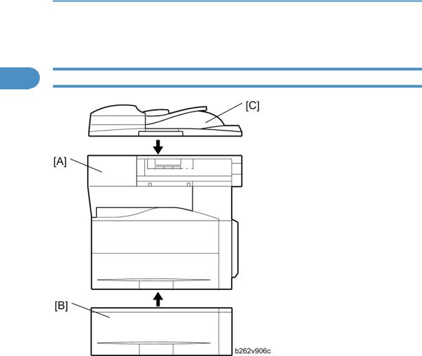
1 Mainframe (D108)
|
Standard Component |
|
Machine Code |
|
Remarks |
|
|
|
|
|
|
1 |
Copier [A] |
|
D108 |
- |
|
|
|
|
|
|
|
|
|
|
|
|
|
|
Optional Components |
|
Machine Code |
|
Remarks |
|
|
|
|
|
|
2 |
500-Sheet Paper Feed Unit [B] |
|
B421 |
|
- |
|
|
|
|
|
|
|
|
|
|
|
|
|
Standard/Optional Component |
|
Machine Code |
|
Remarks |
|
|
|
|
|
|
3 |
ARDF [C] |
|
B872 |
|
- |
|
|
|
|
|
|
18

Overview
Overview
|
|
Component Layout |
1 |
|
|
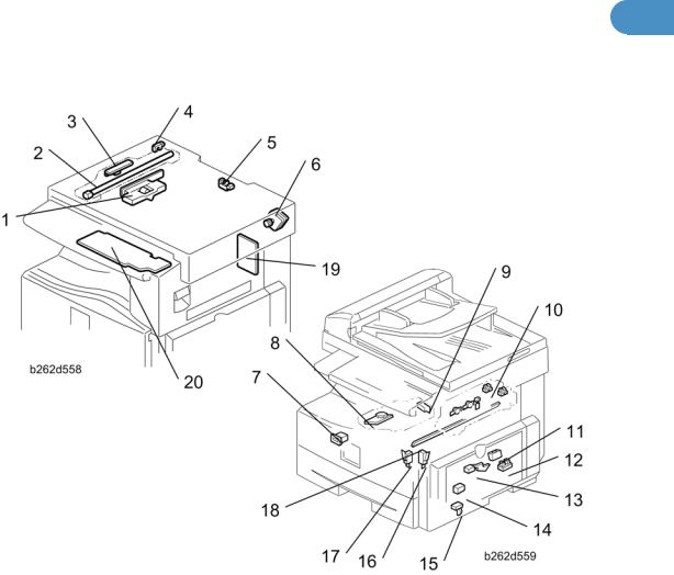
Mainframe
1. |
Exposure Lamp |
20. |
ID (Image Density) Sensor |
|
|
|
|
2. |
1st Scanner |
21. |
Registration Roller |
|
|
|
|
3. |
CCD (on SBU) |
22. |
Registration Sensor |
|
|
|
|
4. |
Lens Block |
23. |
Bypass Tray |
|
|
|
|
5. |
2nd Scanner |
24. |
Bypass Paper Feed Roller |
|
|
|
|
6. |
2nd Mirror |
25. |
Bypass Paper End Sensor |
|
|
|
|
7. |
3rd Mirror |
26. |
Bypass Friction Pad |
|
|
|
|
19
1. Product Information
|
8. Platen Cover Sensor |
27. |
Mixing Augers |
|
|
|
|
|
|
|
9. Exposure Glass |
28. |
(Main) Friction Pad |
|
1 |
|
|
|
|
10. |
Exit Roller |
29. |
Paper Feed Roller |
|
|
|
|
|
|
|
11. |
Exit Sensor |
30. |
Paper End Sensor |
|
|
|
|
|
|
12. |
Scanner Motor |
31. |
TD (Toner Density) Sensor |
|
|
|
|
|
|
13. |
Hot Roller |
32. |
Bottom Plate |
|
|
|
|
|
|
14. |
Pressure Roller |
33. |
Polygon Mirror Motor |
|
|
|
|
|
|
15. |
Cleaning Blade |
34. |
Laser Unit |
|
|
|
|
|
|
16. |
OPC Drum |
35. |
Toner Supply Bottle (or THM) |
|
|
|
|
|
|
17. |
Discharge Plate |
36. |
Toner Collection Coil |
|
|
|
|
|
|
18. |
Transfer Roller |
37. |
Scanner HP Sensor |
|
|
|
|
|
|
19. |
Development Roller |
|
|
|
|
|
|
|
ARDF
1. |
Separation Roller |
7. |
Exit Roller |
|
|
|
|
|
|
2. |
Paper Feed Roller |
8. |
Exit Sensor |
|
|
|
|
|
|
3. |
Pick-up Roller |
9. |
Registration Sensor |
|
|
|
|
|
|
4. |
Original Set Sensor |
10. |
Registration Roller |
|
|
|
|
|
|
5. |
Inverter Roller |
11. |
Inverter Sensor |
|
|
|
|
|
|
20
|
Overview |
|
|
|
|
|
|
|
6. Junction Gate |
12. Transport Roller |
|
|
|
|
|
|
|
Electrical Components |
|
1 |
Electrical Components 1 |
|
|
|
|
|
1. |
Lens Block |
11. |
ID (Image Density) Sensor |
|
|
|
|
2. |
Exposure Lamp |
12. |
Registration Sensor |
|
|
|
|
3. |
Lamp Stabilizer Board |
13. |
Paper End Sensor |
|
|
|
|
4. |
Scanner HP Sensor |
14. |
Toner Density Sensor |
|
|
|
|
5. |
Platen Cover Sensor |
15. |
Bypass Paper End Sensor |
|
|
|
|
6. |
Scanner Motor |
16. |
Right Door Safety Switch |
|
|
|
|
21
1. Product Information
|
7. |
Mechanical Counter |
17. |
Front Door Safety Switch |
|
|
|
|
|
|
8. |
Polygon Mirror Motor |
18. |
Quenching Lamp |
1 |
|
|
|
|
9. |
LD Unit |
19. |
High-Voltage Power Supply Board |
|
|
|
|
|
|
|
10. Exit Sensor |
20. |
Operation Panel Board |
|
|
|
|
|
|
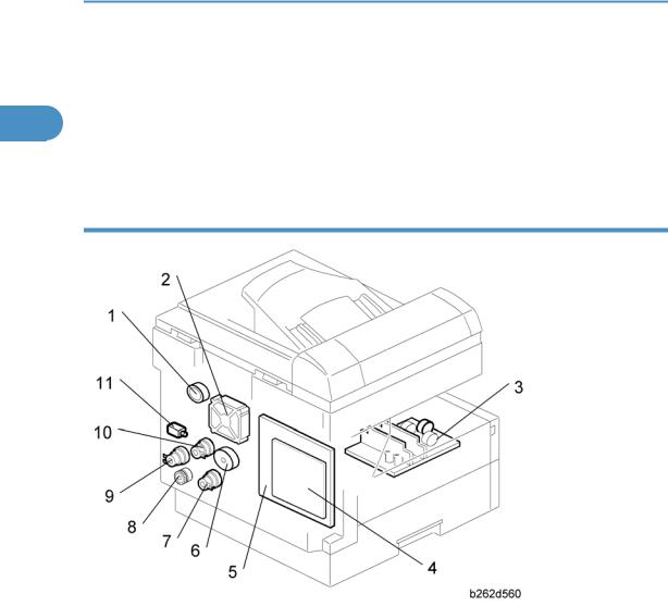
Electrical Components 2
1. |
Duplex Motor |
7. |
Paper Feed Clutch |
|
|
|
|
|
|
2. |
Exhaust Fan |
8. |
Toner Supply Clutch |
|
|
|
|
|
|
3. |
PSU |
9. |
Bypass Feed Clutch |
|
|
|
|
|
|
4. |
Controller Board |
10. |
Registration Clutch |
|
|
|
|
|
|
5. |
BICU |
11. |
Fusing Solenoid |
|
|
|
|
|
|
6. Main Motor |
|
|
|
|
|
|
|
|
|
22

Overview
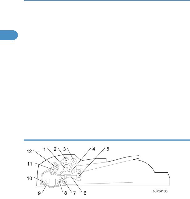
ARDF
1
1. |
DF Feed Clutch |
6. |
DF Feed Motor |
|
|
|
|
2. |
Registration Sensor |
7. |
Inverter Sensor |
|
|
|
|
3. |
Exit Sensor |
8. |
DF Drive Board |
|
|
|
|
4. |
Left Cover Sensor |
9. |
Junction Gate Solenoid |
|
|
|
|
5. |
DF Transport Motor |
10. Original Set Sensor |
|
|
|
|
|
23
1. Product Information
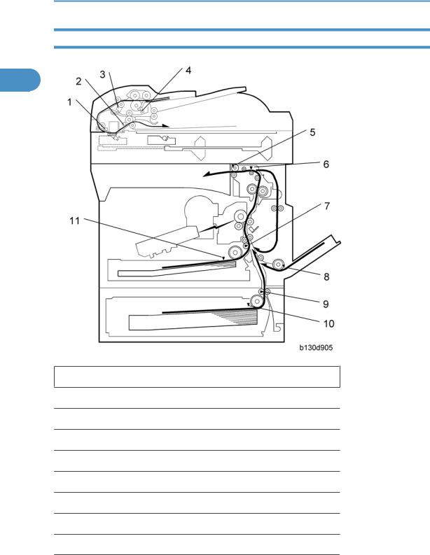
Paper Path
1
1.Original Registration Sensor (Document Feeder)
2.Exit Senor (Document Feeder)
3.Inverter Sensor (Document Feeder)
4.Original Set Sensor (Document Feeder)
5.Exit Sensor
6.Paper Path Sensor
7.Registration Sensor
8.By-pass Paper End Sensor
9.Paper Feed Sensor (Optional Tray)
24
Overview
10.Paper End Sensor (Optional Tray)
11.Paper End Sensor
1
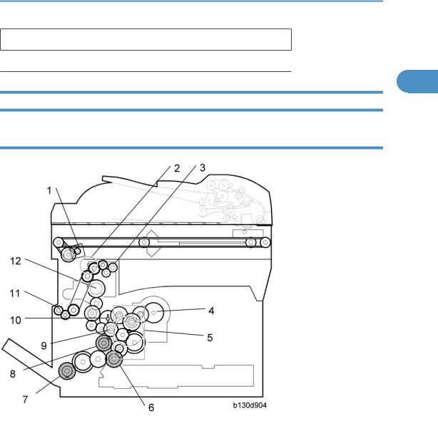
Drive Layout
Mainframe
1. |
Scanner Motor |
7. |
Bypass Feed Clutch (By-pass Tray) |
|
|
|
|
2. |
Duplex motor |
8. |
Registration Clutch |
|
|
|
|
3. |
Exit Roller |
9. |
Developer Driver Gear |
|
|
|
|
4. |
Toner Bottle Clutch |
10. Drum Drive Gear |
|
|
|
||
5. Main Motor |
11. One-way Gear (Duplex Unit) |
||
|
|
|
|
6. |
Paper Feed Clutch |
12. Fusing Drive Gear |
|
|
|
|
|
25
1. Product Information
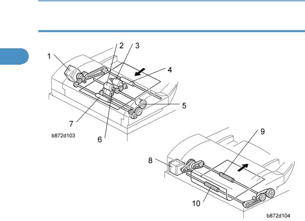
ARDF
1
1. |
DF Feed Motor |
6. |
Separation Roller |
2. |
Feed Roller |
7. |
Transport Roller |
3. |
Pick-up Roller |
8. |
DF Transport Motor |
4. |
Inverter Roller |
9. |
Exit Roller |
5. |
DF Feed Clutch |
10. Registration Roller |
|
|
|
|
|
•DF Feed Motor: Drives the feed, separation, pick-up, and transport and inverter rollers.
•DF Transport Motor: Drives the registration and exit rollers.
26

Guidance for Those Who are Familiar with Predecessor Products
Guidance for Those Who are Familiar with Predecessor Products
The D108 range of machines is the successor model to the B129/B130/B168/B169 range of machines. 1 If you have experience with the predecessor line, the following information may be of help when you read
this manual.
Differences from Predecessor Products
|
D108 |
B129/B130/B168/B169 |
|
|
|
|
|
Controller |
GDI Controller |
- |
|
|
|
|
|
Copying Speed |
17ppm: Memory copy |
15ppm |
|
16ppm: ADF 1 to 1 |
|||
|
|
||
|
|
|
27

1. Product Information
1
28
Loading...