


coretech
Table of contents
 Loading...
C
ONTENTS
• Introduction
• Handling Paper
• Photocopying Processes
• Digital Processes
• Facsimile Processes
• Process Control
• Color Processes
• Standard Components
©Ricoh CO., LTD., 1999. All rights reserved.
C
C
C
O
O
O
R
R
R
E
E
E
T
T
T
E
E
E
C
C
C
H
H
H
N
N
N
O
O
O
L
L
L
O
O
O
G
G
G
Y
Y
Y
M
M
M
A
A
A
N
N
N
U
U
U
A
A
A
L
L
L

I
I
n
n
t
t
r
r
o
o
d
d
u
u
c
c
t
t
i
i
o
o
n
n
Purpose and Scope
What is it for?
The Core Technology Manual is a reference source for standard technologies used in Ricoh office
products. It has three main intended uses.
1. Support for Service Manuals
Instead of repeating a common technical description, a service manual can refer to the description
of the process in the Core Technology Manual. Or the service manual can refer the reader to the
Core Technology Manual for additional information. Thus service manuals can be made more
compact and more focused on the target machine.
2. General Technical Reference
Technical staff and field service personnel can use this manual as a standard technical reference
about Ricoh office machines. It may be especially useful as a memory refresher concerning the
technical aspects of the various products that are often encountered in the field.
3. Source for Training Material
This manual can be used as a source of background material when preparing technical training
courses.
Purpose and Scope
How to use this manual
7 October 1999 Page 2

Introduction How to use this manual
Scope
While the Core Technology Manual can be studied, it is intended primarily for use as a reference. It
doesn’t cover all technical aspects of Ricoh office products. Instead, it concentrates on the common
technologies used in many products. Generally, leading edge technology and machine specific
technology will not be covered.
This manual will be updated from time to time as technology evolves and field needs change.
How to use this manual
The Portable Document Format
This manual is a PDF (portable document format) file, and you must use Acrobat Reader or Acrobat
Explorer to view it. We assume that you are familiar with the features of Adobe Acrobat. If not,
please take a few minutes to familiarize yourself with Acrobat’s navigation features. To make best
use of this and other electronic documents, you need to know how to use the navigation buttons,
bookmarks, thumbnails, and searching functions. (Acrobat comes with several reference and tutorial
documents that you can use to “book up” on Acrobat.)
7 October 1999 Page 3

Introduction How to use this manual
Navigating
This manual has numerous links that allow you to quickly jump to related information. The links are
indicated by green italic text. Also, this manual is heavily bookmarked. You can get almost anywhere
you need to by “drilling down” through the bookmarks. In addition the manual is fully indexed; so, you
can use Acrobat’s full text search function to locate items by keyword searches.
Printing this manual
This manual is formatted for screen viewing. The actual formatted size is A5; however, if you print to
A5 paper, some of the image may be cut at the margins depending on the capabilities of the printer.
If this happens, print to a slightly larger size paper. ISO B5 and JIS B5 work well. As colors are used
in this manual you will get better results by using a color printer.
7 October 1999 Page 4

H
H
a
a
n
n
d
d
l
l
i
i
n
n
g
g
P
P
a
a
p
p
e
e
r
r
There are several key factors involved with handling paper in office machines (copiers, printers,
faxes, whatever). First, there has to be a stock of paper from which to feed, which implies some kind
of holder—a tray, a cassette, or a roll—which positions the paper properly for feeding. Second, there
has to be a method of separating a single sheet from the source; this is referred to as paper feed.
Finally, most machines use sensors to detect paper size and detect the presence or absence of
paper.
After paper is fed into a machine, it must be transported to a registration mechanism, then to an
imaging section where the image is transferred to the paper. Finally the paper passes through an
image fusing section and exits the machine.
Paper Feed
Paper feed is the separation of a single sheet of paper from a paper source—usually a stack of
paper in a cassette or tray—and moving it into the machine.
Paper Feed
Registration
Paper Transport
Duplexing
Misfeed Detection
7 October 1999 Page 5
Handling Paper Paper Feed
Paper Feed Methods
Feed and Reverse Roller (FRR)
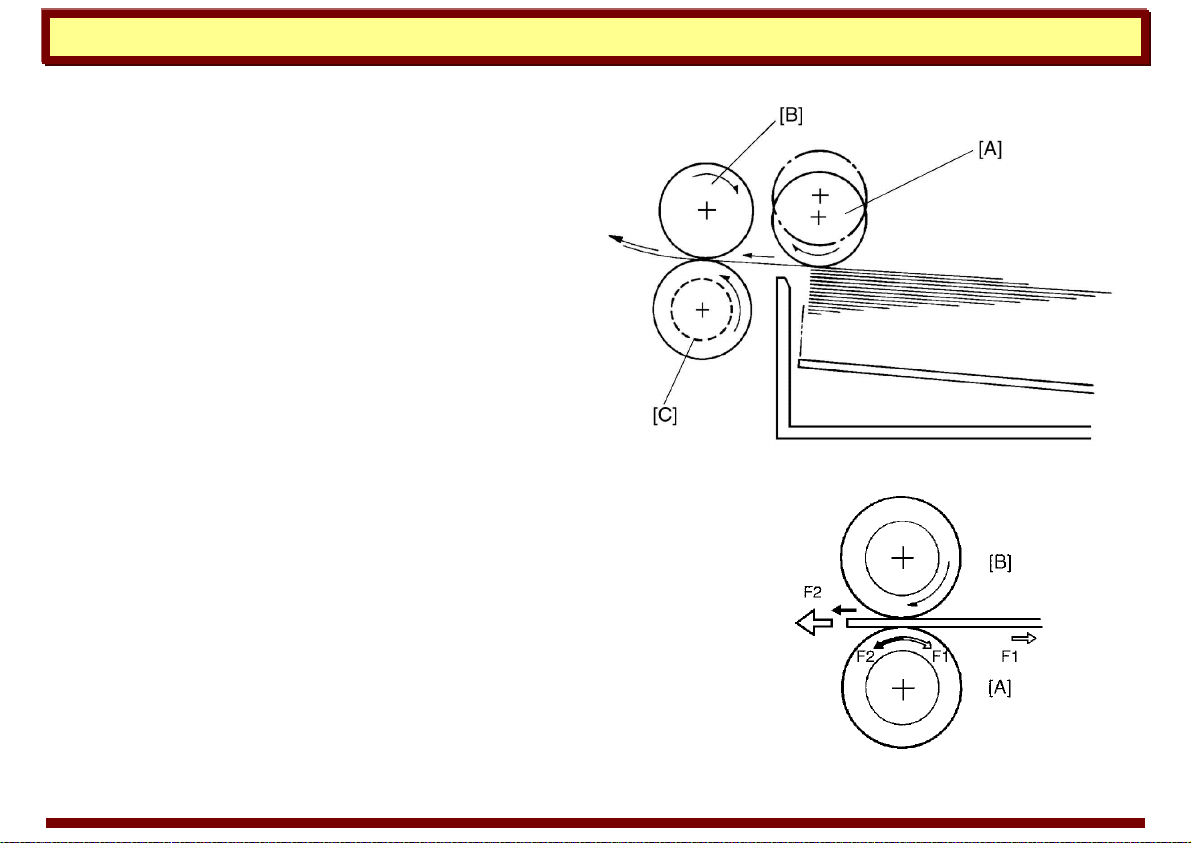
The FRR feed mechanism consists of a pick-up
roller, a feed roller, and a reverse roller.
The pick-up roller [A] is not in contact with the
paper stack before it starts feeding paper. Shortly
after the start key is pressed, the pick-up roller
drops down and feeds the top sheet between the
feed roller [B] and the reverse roller [C]. At almost
the same time that the paper’s leading edge
arrives at the feed roller, the pick-up roller lifts off
the paper stack so that it does not interfere with
the operation of the feed and reverse rollers. The
feed and reverse rollers then take over the paper feed process.
There is a one-way bearing inside the feed roller so it can turn
only in one direction. The reverse roller turns in the opposite
direction as the feed roller. A slip clutch (torque limiter clutch)
drives the reverse roller, however, allowing it to turn in either
direction depending on the friction between the rollers. A spring
keeps the reverse roller in contact with the feed roller.
frr1.jpg
frr2.tif
7 October 1999 Page 6
Handling Paper Paper Feed
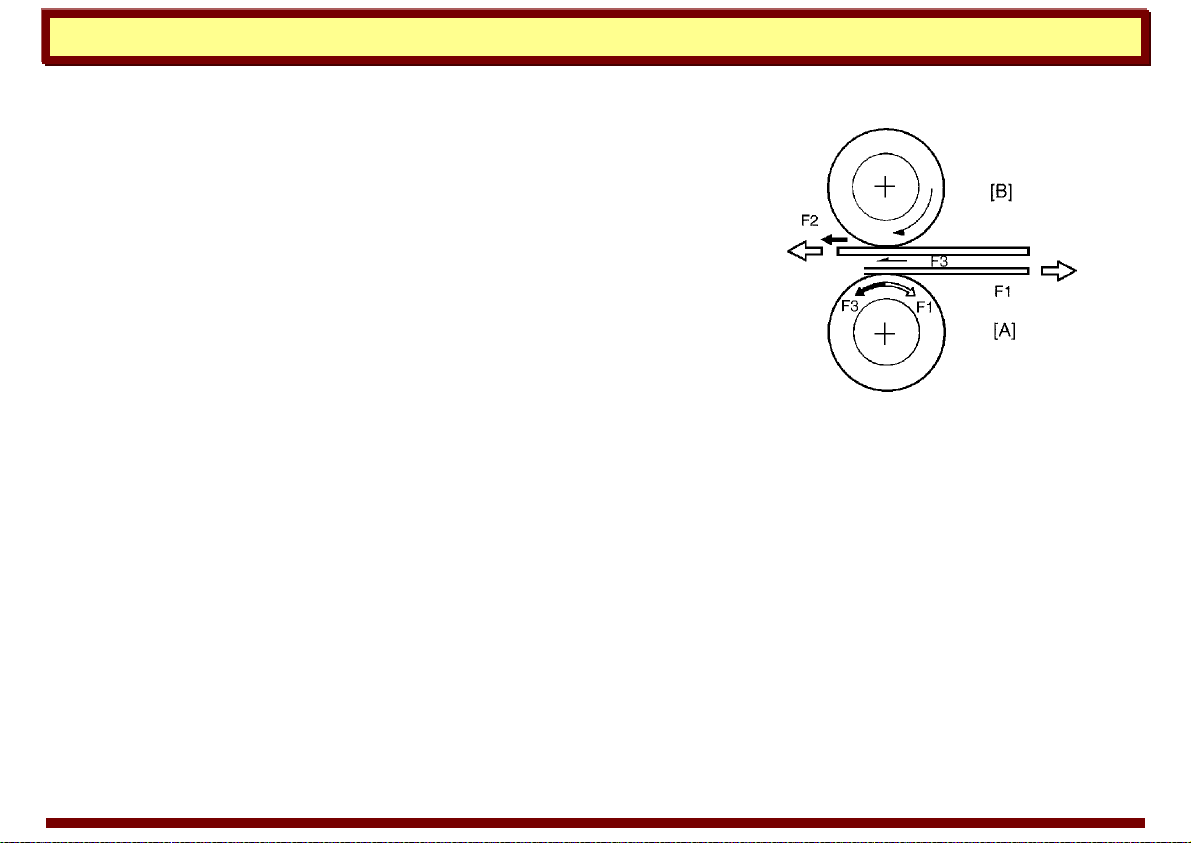
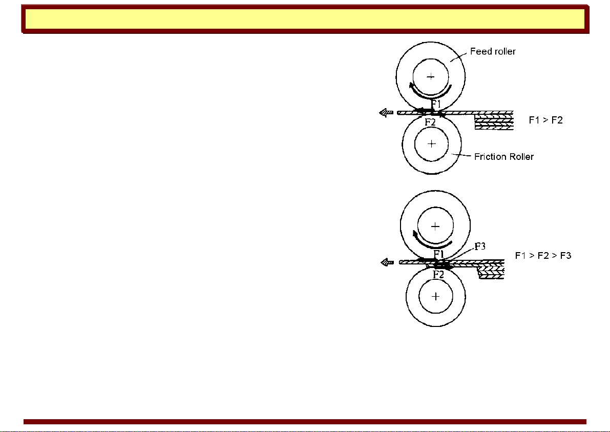
The direction that the reverse roller [A] turns depends on the
frictional forces acting on it. The slip clutch applies a constant
clockwise force (F1). When there is a single sheet of paper being
driven between the rollers, the force of friction between the feed
roller [B] and the paper (F2) is greater than F1. So, the reverse
roller turns counterclockwise.
If two or more sheets are fed between the rollers, the forward
force on the second sheet (F3), becomes less than F1 because
the low coefficient of friction between the two sheets. So, the
reverse roller starts turning clockwise and drives the second
sheet back to the cassette.
frr3.tif
7 October 1999 Page 7
Handling Paper Paper Feed
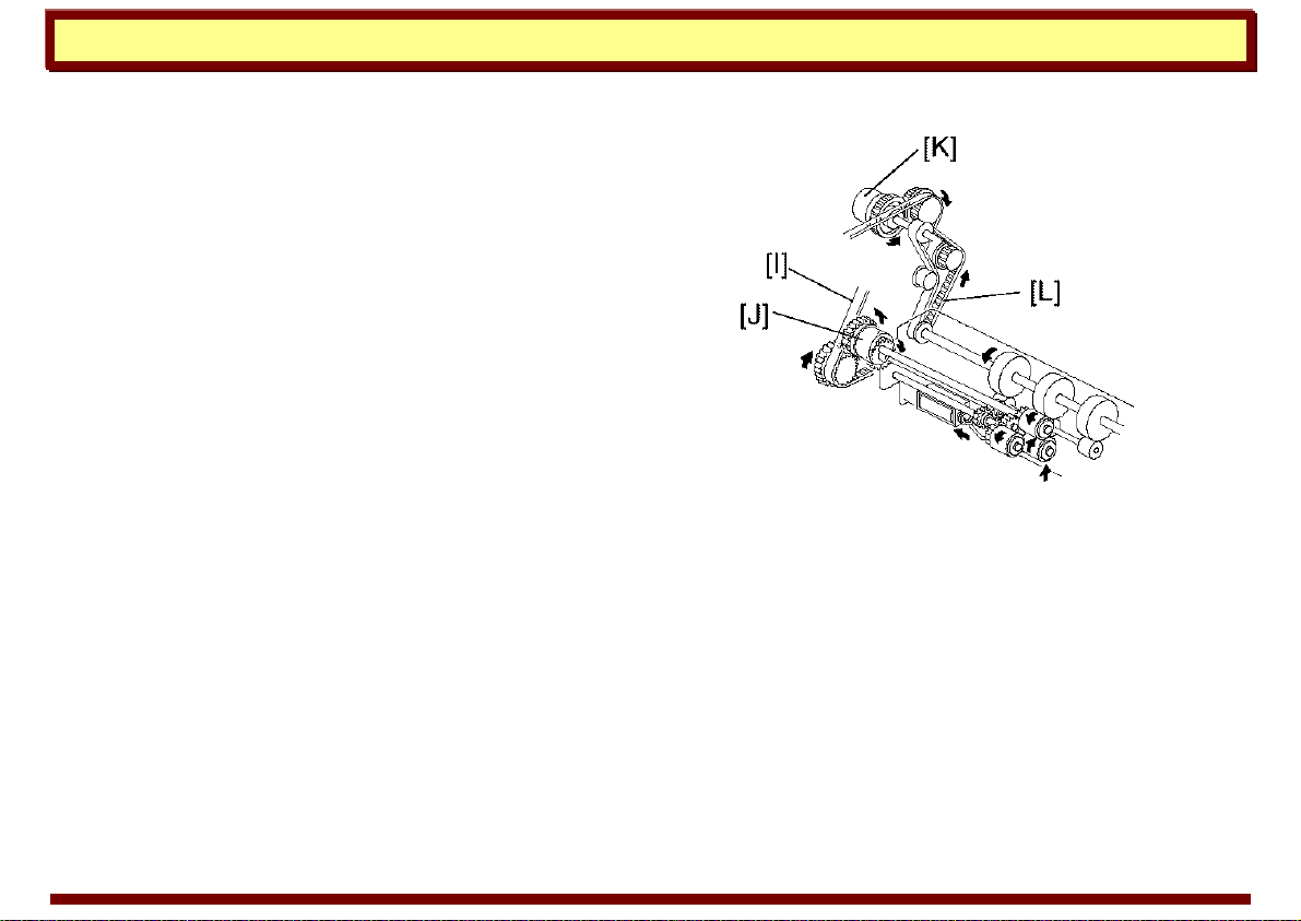
Example: Model A113
Drive Mechanism
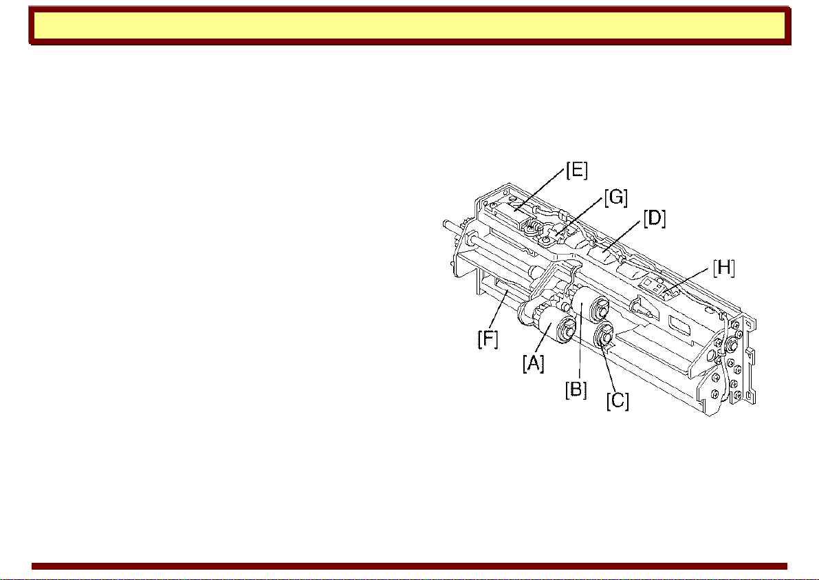
The paper feed unit consists of a pick-up roller [A],
feed roller [B], separation roller [C], relay roller [D],
pick-up solenoid [E], separation solenoid [F],
paper upper limit sensor [G], and paper end
sensor [H].
The main motor drives the pick-up, feed, and
separation rollers via the timing belt [I] and the
paper feed clutch [J]. The main motor also drives
the relay roller. However, drive is transmitted to
the relay roller via the relay clutch [K] and the
timing belt [L].
In stand-by mode, the separation roller is away
from the feed roller. 50 ms after pressing the start
key, the main motor and the separation solenoid
turn on. Then the separation roller comes in
contact with the feed roller. 100 ms after the main
motor starts to rotate, the pick-up solenoid turns
on. The pick-up roller lowers to make contact with
the top of the paper stack. The pick-up solenoid
stays on for 550 ms.
frr4.tif
7 October 1999 Page 8
Handling Paper Paper Feed
200 ms after the main motor starts to rotate, the
paper feed clutch and the relay clutch turn on. The
feed roller and relay rollers feed the top sheet of
the paper stack to the registration rollers. When
the leading edge of the paper passes through the
upper relay sensor, the paper feed clutch is de-
energized.
frr5.tif
7 October 1999 Page 9
Handling Paper Paper Feed
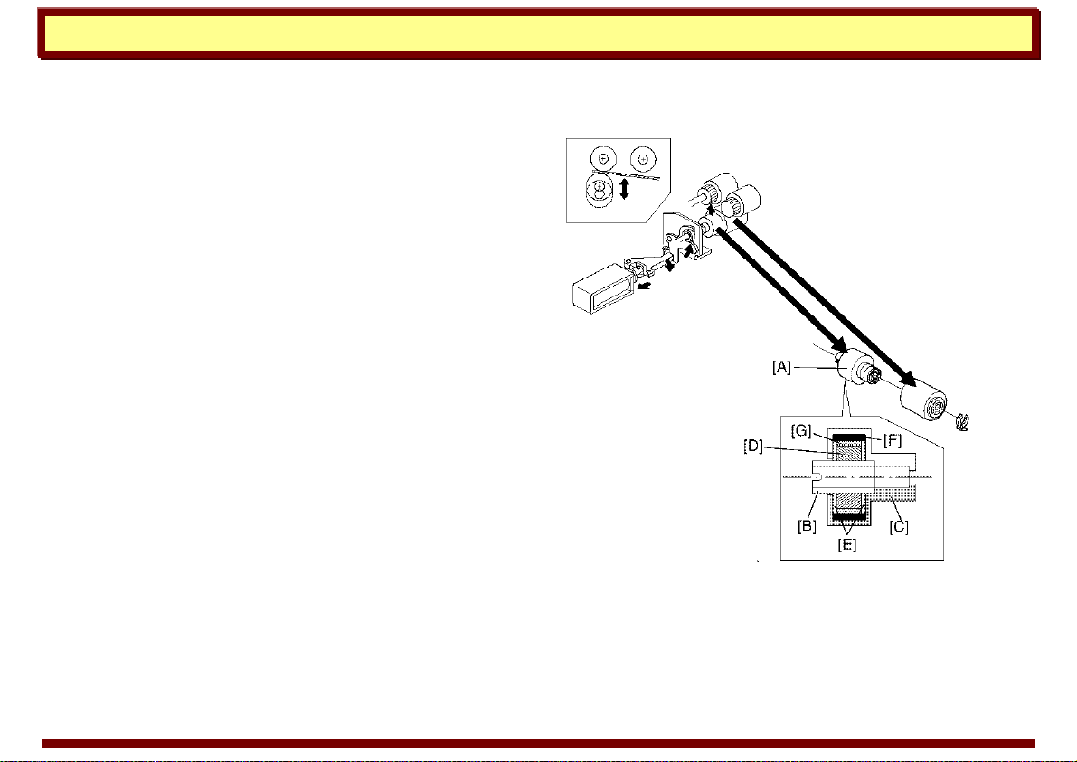
Slip-clutch Mechanism
The separation roller is mounted on a slip clutch.
The slip clutch [A] consists of an input hub [B] and
an output hub [C], which also acts as the case of
the clutch. A magnetic ring [D] and steel spacers
[E] are fitted onto the input hub. A ferrite ring [F] is
fitted into the output hub. Ferrite powder [G]
packed between the magnetic ring and the ferrite
ring generates a constant torque due to magnetic
force. The input hub and the output hub slip when
the rotational force exceeds this constant torque.
The constant torque prevents double feeding,
because it exceeds the coefficient of friction
between sheets of paper. This type of slip clutch
does not require lubrication.
frr6.tif
7 October 1999 Page 10
Handling Paper Paper Feed
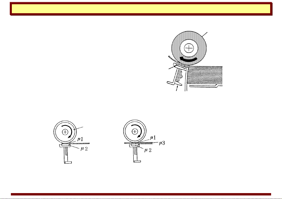
Friction Pad
The friction pad mechanism has two principle
components—the paper feed roller [A] and a friction
pad [B].
When the paper feed roller rotates, it feeds the top
sheet of paper. The second sheet also tries to feed,
but because the friction force between the friction pad
and the second sheet is greater than that between the
first and second sheets, the first sheet of paper is the
only one that feeds.
The friction coefficient applied to the surface of each
sheet of paper is shown below.
020117.tif
[A]
[B]
0201 18. tif
µ1>µ2>µ3
7 October 1999 Page 11

Handling Paper Paper Feed
Example: Model A074
When the paper tray is placed in the copier, it
pushes the pressure release lever [A], causing it
to turn clockwise. This then causes the friction
pad holder [B], holding the friction pad, to press
up against the paper feed roller [C]. The friction
pad pressure against the paper feed roller is
determined by the friction pad pressure spring
[D]. This pressure is applied evenly to the paper
feed roller because the friction pad holder is
mounted on the mounting bracket [E] with a
swivel bushing.
fricpad.tif
7 October 1999 Page 12
Handling Paper Paper Feed
Friction roller
The paper separation mechanism for the friction roller uses
the same principles as the paper separation method for the
friction pad.
The two main components are the paper feed roller and the
friction roller. When the paper feed roller rotates, the top
sheet of paper is fed. The second sheet also tries to feed, but
as the friction force between the friction roller and the second
sheet is greater than that between the first and second
sheets, only the first sheet of paper is fed.
fricroll1.tif
7 October 1999 Page 13
Handling Paper Paper Feed
Example: Model
A133
Duplex
The duplex paper feed system consists of three
sets of duplex feed rollers and a friction roller [A].
The friction roller has a one-way bearing inside;
therefore, it rotates freely during paper stacking
and locks during paper feeding. The duplex feed
rollers can only feed the top sheet of the stack
because the friction roller functions in the same
way as a friction pad does.
a133d587.wmf
[A]
7 October 1999 Page 14
Handling Paper Paper Feed
Separation Belt
The separation belt system (also called the
“friction belt” system) primarily feeds sheets from
the bottom of a stack. It is commonly employed in
automatic document feeders (ADFs) and in
duplexing systems.
The separation belt feed mechanism is similar to
the friction pad and friction roller systems; it
exploits the difference in friction resistance to
separate a single sheet of paper. However, unlike
these two systems, the separation belt does not
passively resist the passage of extra sheets of
paper; it turns against the movement of the paper
to feed back all but the bottom sheet.
The mechanism shown to the right is from the
DF62.
[A] Separation belts
[B] Feed rollers
A610d506.wmf
[B]
[A]
7 October 1999 Page 15

Handling Paper Paper Feed
Example: Model A095 Duplex
The illustrations to the right show the model A095
duplex paper feed mechanism.
The paper on the duplex tray feeds in order from
the bottom to the top sheet. After all copies are
stacked on the duplex tray, the duplex pressure
solenoid [A] turns on to lower the pressure arm [B]
causing the pressure arm to press the paper
against the pick-up roller [C].
Then, the paper feed clutch [D] turns on to rotate
the pick-up roller, separation belts [E] and the
feed roller [F]. The separation belts and the feed
roller rotate in opposite directions.
Only the bottom sheet is fed because the
separation belt prevents any other sheets from
feeding.
sepbelt1.wmf
[B]
[
E
]
[A]
sepbelt2.wmf
[C]
[D]
[
F
]
[B]
[
E
]
7 October 1999 Page 16
Handling Paper Paper Feed
Separation Tab
The separation tab separation system is a
variation of the separation belt system. It is used
in slower feeding ADF units.
The illustration shows a document feeder using a
separation tab. The pick-up roller [A] and feed
roller [B] feed the document into the ADF unit.
Only the bottom sheet is fed because the
separation tab [C] prevents any other sheets from
feeding. The document feed-in roller [D], feeds the
document through the ADF unit.
g025d504.wmf
[B]
[C]
[D]
[A]
7 October 1999 Page 17

Handling Paper Paper Feed
Corner Separator
Corner separators provide a simple and reliable
method of separating off the top sheet during
paper feed. Commonly, they are used along with
semicircular feed rollers in low and medium speed
copiers.
A spring [A] holds the paper stack up against the
underside of the corner separators [B]. As the
feed rollers [C] start forcing the paper forward, the
corner separators retard the movement of the
paper causing the top sheet to bow up at the
edges and thus separate from the lower sheets.
With further feeding, the corners of the top sheet
release from the corner separators. The top sheet
then feeds into the paper path while the corner
separators stop the lower sheets from feeding.
cor_sep.tif
[B]
[C]
[A]
7 October 1999 Page 18
Handling Paper Paper Feed
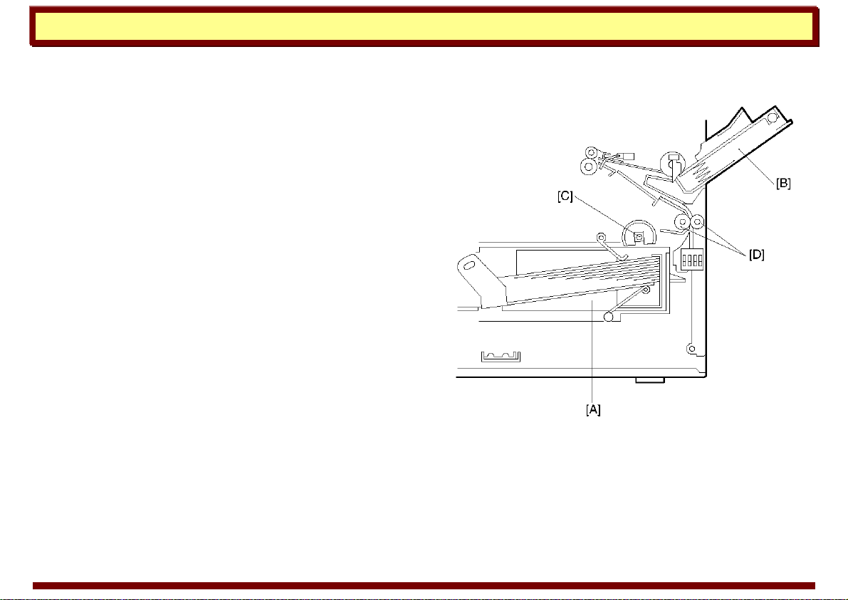
Example: Model A219
This copier has one paper feed station and a by-
pass feed table. The paper feed station uses a
paper tray [A] that can hold 500 sheets. The by-
pass feed table [B] can hold 80 sheets.
The paper tray uses two semicircular feed rollers
[C] and corner separators. The semicircular feed
rollers make one rotation to drive the top sheet of
the paper stack to the relay rollers [D]. The two
corner separators allow only one sheet to feed.
They also hold the paper stack. When the paper
tray is drawn out of the machine, the spring
pressure is released, and the tray bottom plate
drops. In addition, there is no need to press the
bottom plate down when putting the tray back in.
The by-pass feed table uses a feed roller and
friction pad system to feed the top sheet of paper
to the registratio n rollers.
cor_sep2.tif
7 October 1999 Page 19
Handling Paper Paper Feed
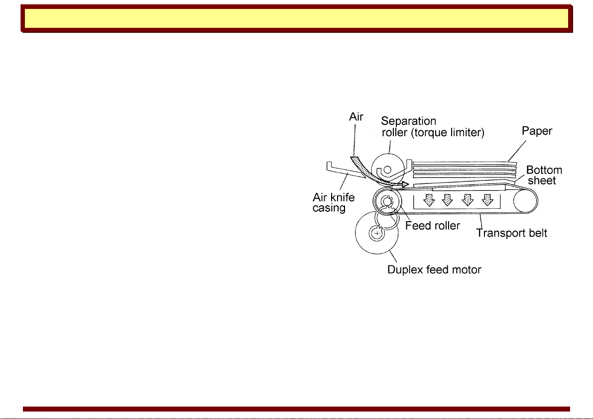
Air Knife
The air knife paper feed process uses jets of air to
separate sheets of paper for paper feed. The air
knife method (also called “air separation” method)
is suitable for high speed copying and printing
systems because it reduces the feed roller marks
and paper deformation that can occur in high
speed feeding.
The duplex paper feed mechanism of model A112
(right) uses a combination of air knife and FRR
feed mechanisms. The air knife directs jets of air
at the bottom of the paper stack to separate the
sheets of paper. A vacuum fan holds the bottom
sheet against the transport belt. The separation
roller allows only the bottom sheet to feed.
airknife.tif
7 October 1999 Page 20

Handling Paper Paper Feed
Paper Cassette
A paper cassette is a removable paper tray. A
cassette is taken out of the machine to load paper
and then reinserted in a cassette holder or
cassette entrance.
Paper Lift Mechanism
Cassettes all have a moveable bottom plate on
which the paper rests. The bottom plate must be
raised to place the paper in position to be fed.
Generally, this is accomplished by raising a
cassette arm under the bottom plate. (Refer to the
following examples.)
cassett1.tif
cassett2.tif
7 October 1999 Page 21
Handling Paper Paper Feed
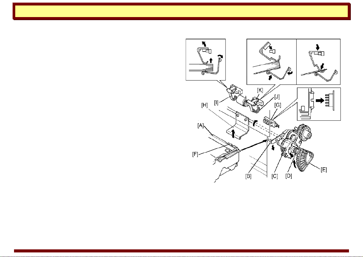
Example 1: Model A111
This is an example of the cassette arm being
raised by a gear.
When inserting the cassette [A] into the copier,
the cassette pushes down the cassette actuator
pin [B]. The paper lift clutch unit [C] moves down
and then the paper lift gear [D] engages with the
sector gear [E] causing the cassette arm [H] to
raise the cassette bottom plate.
Simultaneously, the paper size actuator [F]
actuates the paper size switch [G] and the paper
raises the paper end feeler [I].
cassett3.tif
7 October 1999 Page 22
Handling Paper Paper Feed
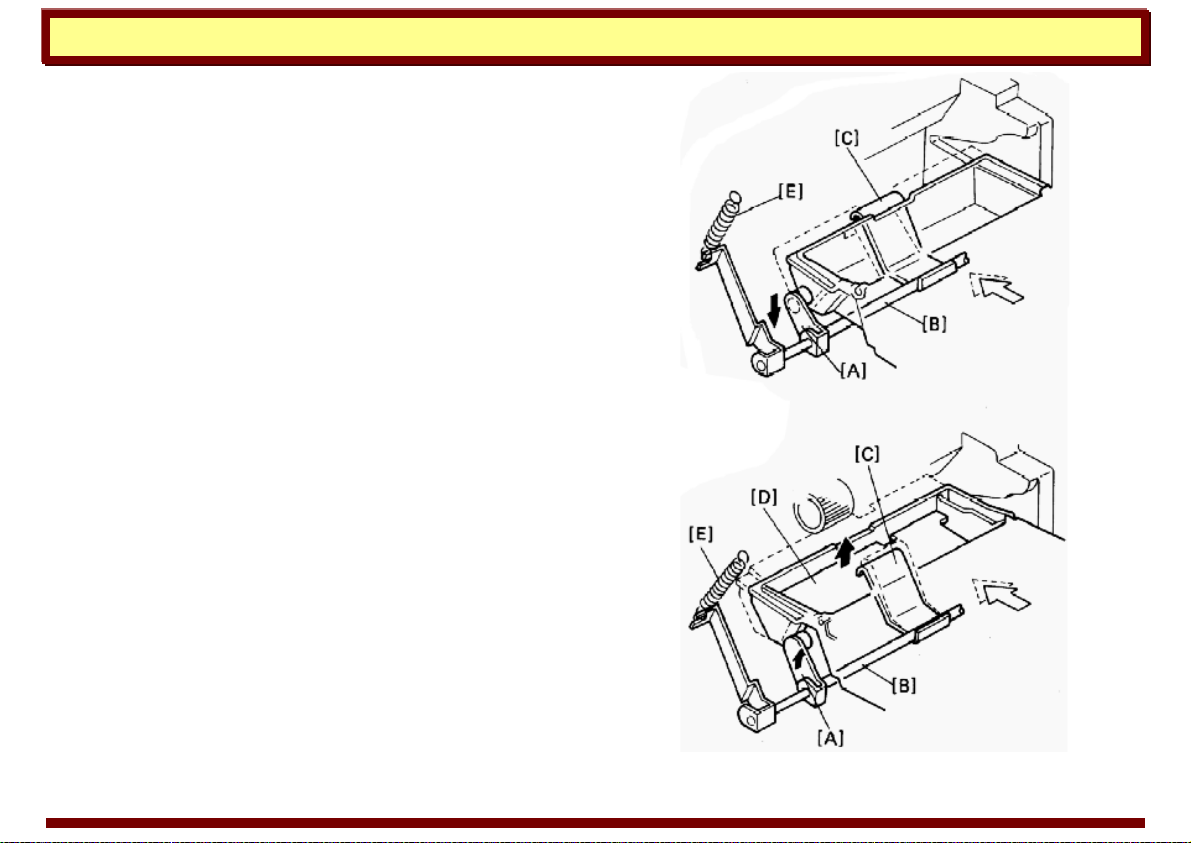
Example 2: Model A006
This is an example of the cassette arm being
raised by a spring.
When a cassette is inserted into the copier, the
curved release guides on the sides of the cassette
press against the rollers on the release levers [A]
and force the release levers down. The release
levers rotate the cassette arm shaft [B], moving
the cassette arm down and out of the way. When
the cassette is fully seated, the release guides
allow the release levers to move back up. The
cassette arm [C] levers up the cassette bottom
plate [D] until the paper contacts the paper feed
roller.
To prevent copy paper from multi-feeding or
jamming, the spring [E] pressure is adjustable.
cassett4.tif
7 October 1999 Page 23
Handling Paper Paper Feed
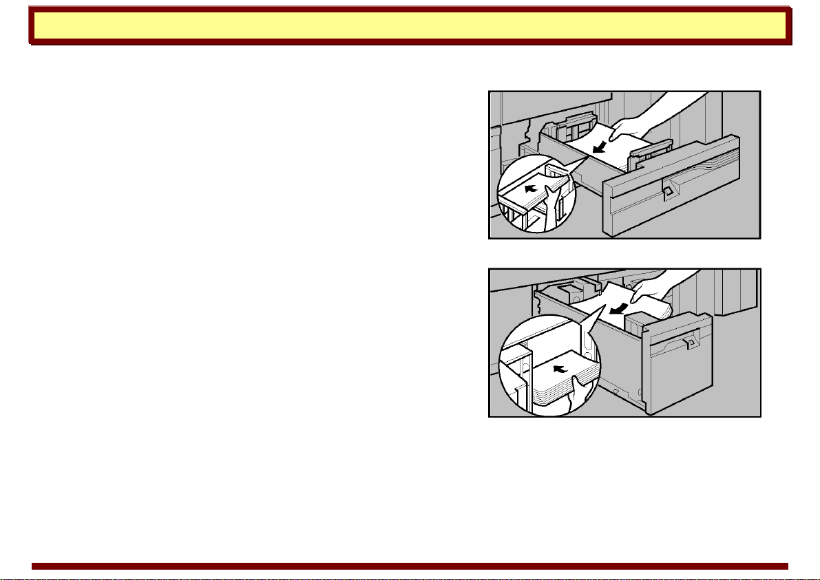
Paper Tray
A paper tray is a non-removable drawer or bin that
is permanently built into or attached to the
machine. The capacity of paper trays varies
considerably; smaller trays typically hold 250 to
500 sheets of paper, but large capacity trays hold
a paper stock of 1000 or more sheets.
Paper Lift Mechanism
Smaller paper trays resemble paper cassettes and
have similar paper lift mechanisms employing
springs or a bottom plate lift arm.
However, large capacity trays have more
complicated mechanisms to raise the bottom plate
and place the paper in position to be fed.
Generally, this is accomplished using a wire- or
belt-lift mechanism. (Refer to the following
examples.)
500_sheet_tray.tif
1700_sheet_tray.tif
7 October 1999 Page 24
Handling Paper Paper Feed
Example 1: Model A609 (belt lift)
The bottom plate [A] of the LCT is raised and lowered by the LCT motor [B] and the drive belts [C].
When the main switch is on and the LCT cover is closed, the pick-up solenoid [D] activates and the
LCT motor [B] rotates clockwise to raise the bottom plate until the top sheet pushes up the pick-up
roller [E]. When the lift sensor [F] is de-actuated, the copier CPU de-activates the LCT motor [B] and
the pick-up solenoid [D].
a609d502.wmf
[D]
[
E
]
[
F
]
a609d501.wmf
[B]
[C]
[A]
[C]
7 October 1999 Page 25

Handling Paper Paper Feed
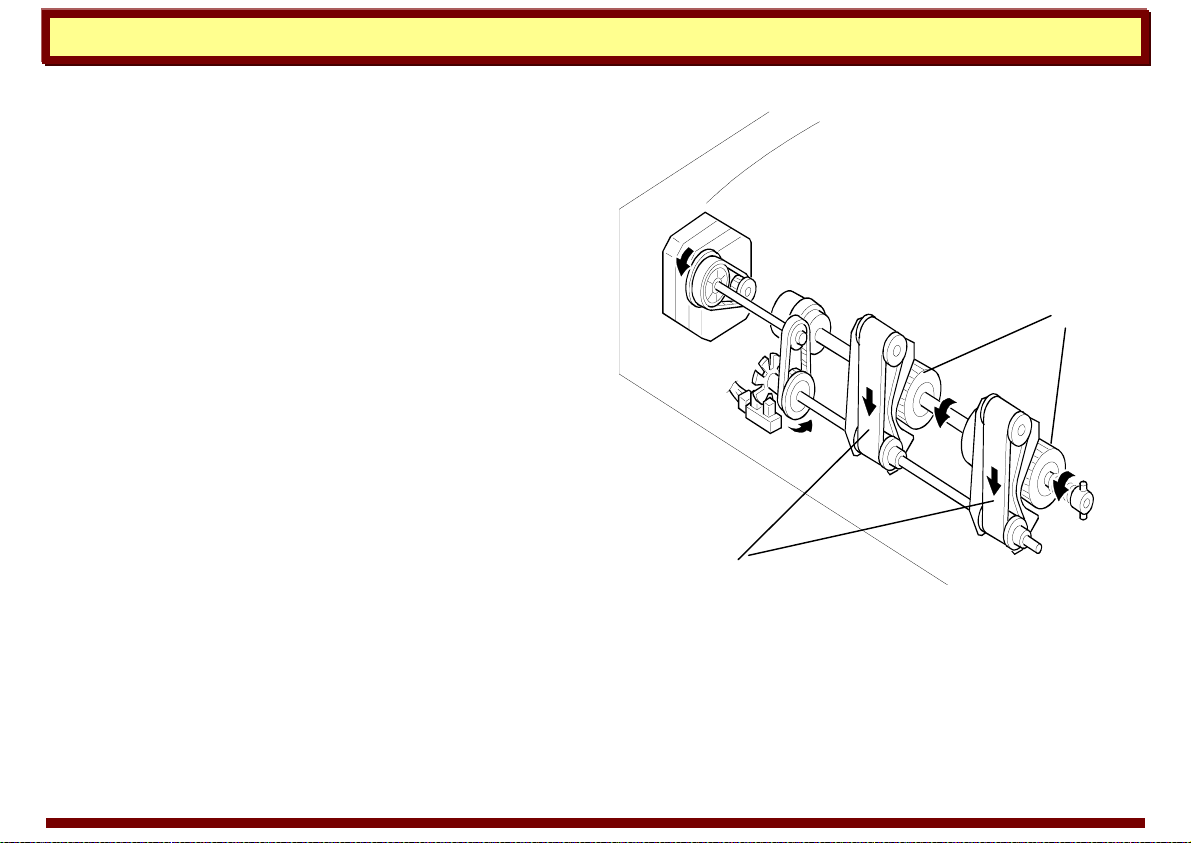
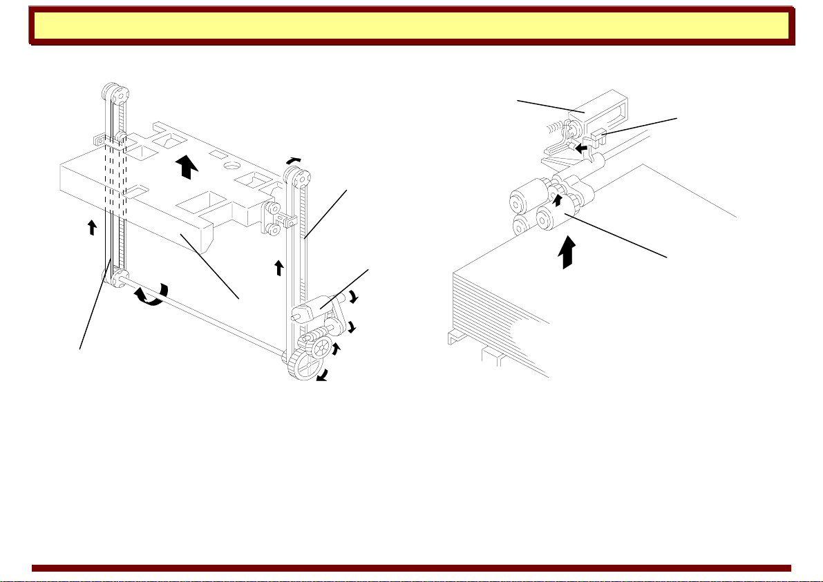
Example 2: Model A171 (wire lift)
Drive from a reversible motor [A] is transmitted trough a
worm gear [B] to the drive pulley [C] shaft. The tray wires
have metal beads on them. These beads are inserted in
the slots at the ends of the tray support bracket [D] of the
bottom plate; so, when the wire pulley turns
(counterclockwise rear view), the beads on the wires drive
the tray support bracket and the tray moves upward. The
tray goes up until the top sheet pushing up the pick-up
roller [E] actuates the upper limit sensor [F]. To lower the
tray, the pulley turns clockwise until the lower limit sensor
[G] is actuated by the of the bottom plate [H] actuator.
a171d620.pcx
[
F
]
E
]
a171d629.pcx
[G]
[H]
a171d628.pcx
[B]
[C]
[D]
[A]
7 October 1999 Page 26

Handling Paper Paper Feed
By-pass Feed Tray
Most copiers and multifunction machines
incorporate a fold-out by-pass feed table. By-pass
feed is useful for casual copying on odd paper
sizes. Also, on most machines, the by-pass feed
tray provides a straight paper path that is suitable
for stiff feed stock such as post cards or OHP
transparencies.
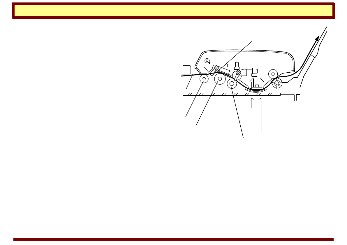
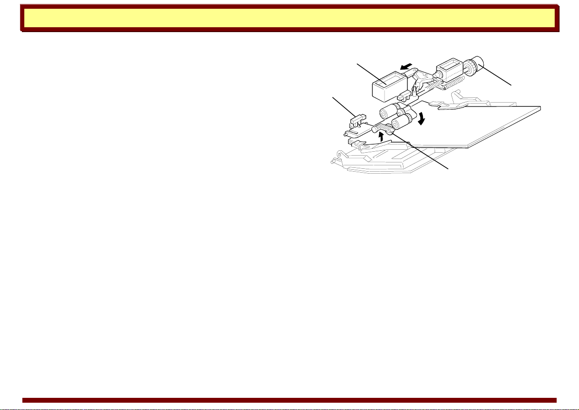
Example: A195
The by-pass feed table switch [A] detects when
the by-pass feed table is opened. Then the CPU
turns on the by-pass feed indicator on the
operation panel.
The by-pass feed table uses an FRR feed system,
using the same rollers as the LCT, and one of the
solenoids. Only the by-pass pick-up solenoid [B] is
used, because the pick-up roller does not have to
drop so far as it does when feeding from the LCT.
The user can put up to 40 sheets of paper on the
by-pass feed table. Note that the paper can be
pushed right into the machine, causing jams. The
[C]
a195d602.wmf
[
A
]
a195d569.wmf
7 October 1999 Page 27
Handling Paper Paper Feed
user must stop pushing the paper in when the by-
pass feed indicator goes out.
When the Start key is pressed, the by-pass feed
clutch [C] and the pick-up solenoid turn on to feed
the top sheet of paper.
When there is no paper on the by-pass feed table,
the paper end feeler [D] drops into the cutout in
the lower guide plate and the by-pass feed paper
end sensor [E] is deactivated.
[B]
a195d604.wmf
[D]
[
E
]
[C]
7 October 1999 Page 28

Handling Paper Paper Feed
Paper Roll
Wide format copiers and machines that use a
thermal printing process commonly feed paper
from a roll.
The illustration to the right shows the main
components of a roll feeding system—the paper
feed rollers [A], the paper roll [B], the cutter unit
[C], and the paper leading edge sensor [D].
sr740-4.pcx
7 October 1999 Page 29
Handling Paper Paper Feed
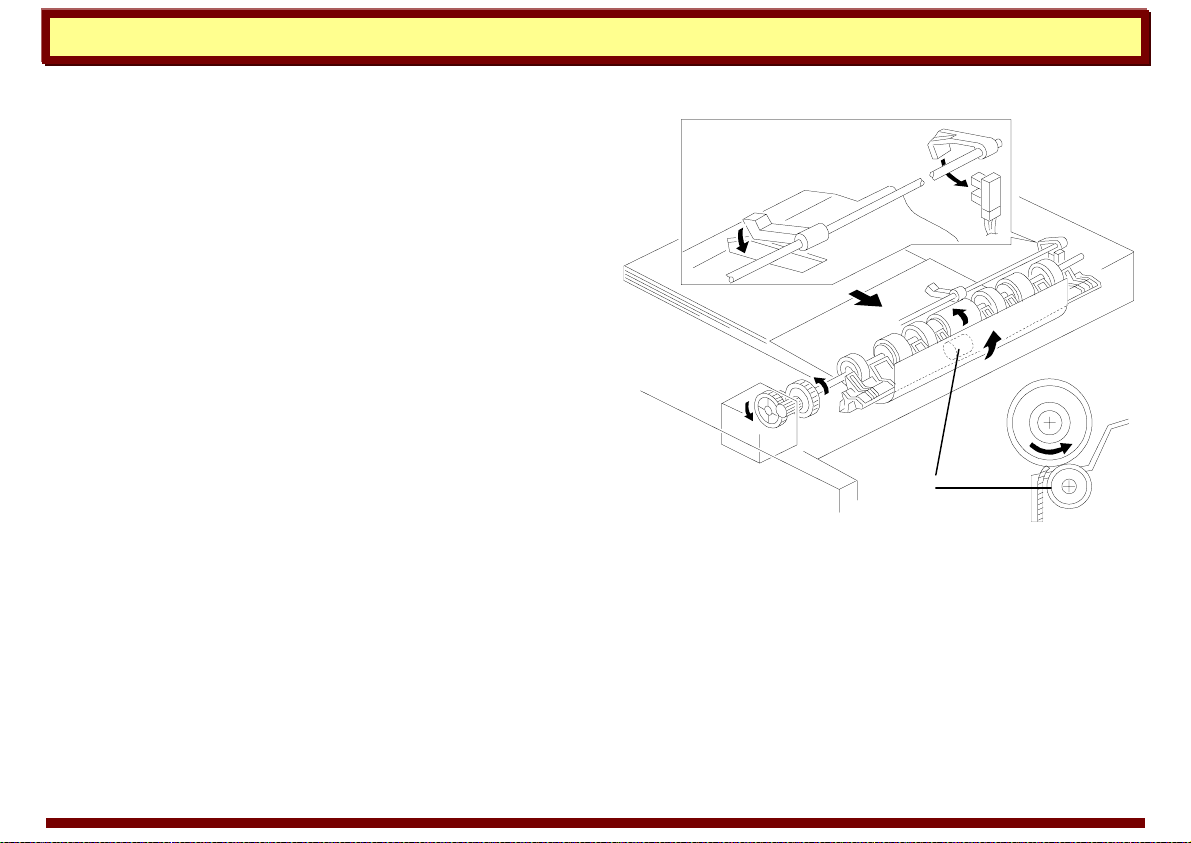
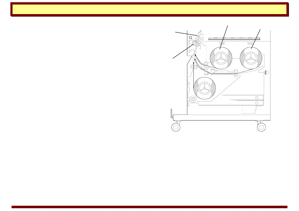
Example: A175
This machine has two standard roll feed units (1st
[A] and 2nd [B]), one manual feed unit, and one
optional roll feed unit (3rd [C]). The cutter unit [D]
uses a sliding rotary cutting blade.
When the main switch is turned on or when roll
paper is replenished, the roll feed motor rotates
and the leading edge of the roll paper is fed until
the roll lead edge sensor [E] is activated. Then,
the leading edge of the roll paper is returned to
the paper feed start position (120 mm before the
cutter unit).
When the original lead edge sensor detects the
leading edge of the original, the roll feed motor
and the roll feed clutch turn on, and paper feed
starts
a174d507.wmf
[B]
[D]
[
E
]
[A]
7 October 1999 Page 30
Loading...