


 Loading...
SECTION 1
OVERALL MACHINE
INFORMATION

1 June 1990
1. SPECIFICATIONS
Configuration:
|
|
Desk top |
|
|
||
Copy Process: |
Dry electrostatic transfer system |
|||||
Originals: |
Sheet/Book |
|
|
|||
Original Size: |
Maximum A3/11"x17" |
|
|
|||
Copy Paper Size: |
Maximum A3/11"x17" |
|
|
|||
|
|
Minimum A6/5 1/2" x 8 1/2" (lengthwise) |
||||
(Duplex Copying) |
A4 and B5/8 1/2" x 11" (sideways) |
|||||
Copy Paper Weight: |
Cassette feed: 52 to 157 g/m2 (14 to 42 lb) |
|||||
|
|
Paper tray feed: 64 to 90 g/m2 (17 to 22 Ib) |
||||
|
|
Manual feed: 52 to 157 g/m2 (14 to 42 lb) |
||||
|
|
Duplex: 59 to 104 g/m2 (16 to 27 lb) |
||||
Reproduction Ratio: |
2 Enlargement and 3 Reduction |
|||||
|
|
|
|
|
|
|
|
|
|
A4/A3 Version |
|
LT/LDG Version |
|
|
Enlargement |
|
141% |
|
155% |
|
|
|
122% |
|
129% |
|
|
|
|
|
|
|
||
|
Full size |
|
100% |
|
100% |
|
|
|
|
93% |
|
93% |
|
|
Reduction |
|
82% |
|
74% |
|
|
|
|
71% |
|
65% |
|
Zoom: |
From 50% to 200% in 1% steps |
|||||
Copying Speed: |
18 copies/minute (A4/8 1/2" x 11" sideways) |
|||||
|
|
10 copies/minute (A3/11" x 17") |
||||
Warm-Up Time: |
60 seconds (at 20oC) |
|
|
|||
First Copy Time: |
5.9 seconds (A4/8 1/2" x 11" sideways) |
|||||
Copy Number Input: |
Ten keys, 1 to 99 (count up) |
|||||
Manual Image Density |
7 steps |
|
|
|||
Selection: |
|
|
|
|
|
|
1-1
1 June 1990 |
|
|
|
|
|
|
|
Automatic Reset: |
1 minute standard setting; can also be set to 3 |
||||||
|
|
minutes or no auto reset. |
|
|
|||
Paper Capacity: |
Cassettes: 500 sheets |
|
|
||||
|
|
Paper tray: 250 sheets |
|
|
|||
|
|
Manual feed table: 50 sheets |
|
|
|||
Toner Replenishment: |
Black: Cartridge exchange (370g/cartridge) |
||||||
|
|
Color (red, blue, & green): Cartridge exchange |
|||||
|
|
|
|
(310g/cartridge) |
|||
Copy Tray Capacity: |
250 sheets (B4/8 1/2" x 14" and smaller) |
||||||
|
|
100 sheets (A3/11" x 17") |
|
|
|||
Power Source: |
110V/ 60Hz/ 15A |
|
|
||||
|
|
115V/ 60Hz/ 15A |
|
|
|||
|
|
220V/ 50Hz/ 8A |
|
|
|||
|
|
220V/ 60Hz/ 8A |
|
|
|||
|
|
240V/ 50Hz/ 8A |
|
|
|||
|
|
(Refer to the serial number plate (rating plate) to |
|||||
|
|
determine the power source required by the |
|||||
|
|
machine.) |
|
|
|
|
|
Power Consumption: |
Maximum: |
1.2 kw |
|
|
|||
|
|
Warm-up: |
0.72 kw (average) |
||||
|
|
Ready: 0.16 kw (average) |
|
|
|||
|
|
Copy cycle: |
0.81 kw (average) |
||||
Dimensions: |
|
|
|
|
|
|
|
|
|
|
|
|
|
|
|
|
|
Width |
|
Depth |
|
Height |
|
|
Copier only |
672 mm |
|
600 mm |
|
410 mm |
|
|
(26.5") |
|
(23.7") |
|
(16.2") |
|
|
|
|
|
|
|
|||
|
Full system |
1149 mm |
|
600 mm |
|
513 mm |
|
|
(45.3") |
|
(23.7") |
|
(20.2") |
|
|
|
|
|
|
|
|||
Weight: |
Copier only: 52 kg (114.7 Ib) |
|
|
||||
|
|
Full system: 71 kg (156.6 Ib) |
|
|
|||
Optional Equipment: |
Document feeder |
|
|
||||
|
|
10 bin sorter |
|
|
|
|
|
|
|
Duplex unit |
|
|
|
|
|
|
|
Color development unit |
|
|
|||
|
|
Key counter |
|
|
|
|
|
|
|
Universal Cassette |
|
|
|||
∙Specifications are Subject to change without notice.
1-2
1 June 1990
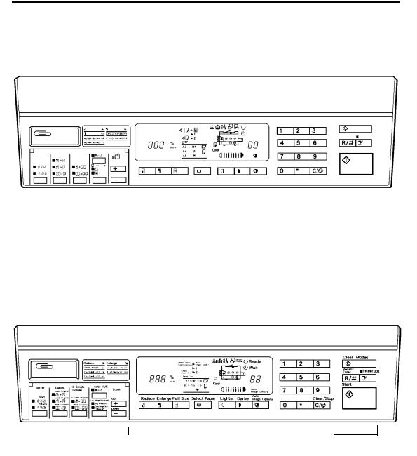
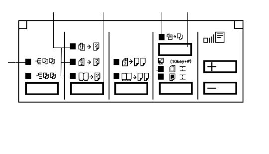
2. OPERATION PANEL
— A4/A3 Version —

 C
C 

 B
B 

 A
A 
— LT/LDG Version —

 C
C 

 B
B 

 A
A
Section A: |
See page |
7. |
Section B: |
See page |
8. |
Section C: |
See page 10. |
|
1-3
1 June 1990
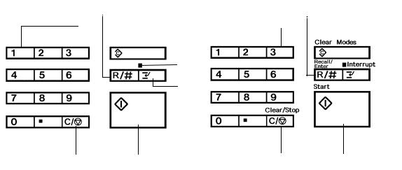
Section A —
— A4/A3 Version — |
— LT/LDG Version — |
1 |
2 |
3 |
1 |
2 |
3 |
||||
|
|
|
|
|
|
|
|
|
|
|
|
|
|
|
|
|
|
|
|
|
|
|
|
|
|
|
|
|
|
|
|
|
|
|
|
|
|
|
|
4 |
|
4 |
|
||
|
|
5 |
|
5 |
|
7 |
6 |
7 |
6 |
1. Number Keys
The number keys are used to enter the desired number of copies. They are also used to input the sizes of the original and the copy image when in size magnification mode.
2. Recall/Enter Key
Press to display the number of copies entered. Also use to enter or change data when in size magnification mode.
3. Clear Modes Key
Press to clear all previously entered settings and modes.
4. Interrupt Indicator
Lights when interrupt mode is selected.
5. Interrupt Key
Press to make interrupt copies during a copy run.
6. Start Key
Press to start copying.
7. Clear/Stop Key
Press to cancel the copy number entered. While copying, press to stop copying.
1-4
1 June 1990
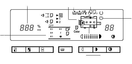
—Section B —
—A4/A3 Version —
1 |
2 |
3 |
4 |
5 6 |
|
7 |
8 9 10 |
|
|
|
|
|
|
|
|||||||||||||
|
|
|
|
|
|
|
|
|
|
|
|
|
|
|
|
|
|
|
|
|
|
|
|
|
|
|
11 |
|
|
|
|
|
|
|
|
|
|
|
|
|
|
|
|
|
|
|
|
|
|
||||||
|
|
|
|
|
|
|
|
|
|
|
|
|
|
|
|
|
|
|
|
|
|
|
|
|
|
|
|
|
|
|
|
|
|
|
|
|
|
|
|
|
|
|
|
|
|
|
|
|
|
12 |
|||||
|
|
|
|
|
|
|
|
|
|
|
|
|
|
|
|
|
|
|
|
|
|
||||||
1 |
|
|
|
|
|
|
|
|
|
|
|
|
|
|
|
|
|
|
|
|
|
|
|
|
|
|
13 |
|
|
|
|
|
|
|
|
|
|
|
|
|
|
|
|
|
|
|
|
|
|
|
|
|
|
||
|
|
|
|
|
|
|
|
|
|
|
|
|
|
|
|
|
|
|
|
|
|
|
|
|
|
||
|
|
|
|
|
|
|
|
|
|
|
|
|
|
|
|
|
|
|
|
|
|
|
|
|
|
||
|
|
|
|
|
|
|
|
|
|
|
|
|
|
|
|
|
|
|
|
|
|
|
|
|
|||
|
|
|
|
|
|
|
|
|
|
|
|
|
|
|
|
|
|
|
|
|
|
|
|
|
14 |
||
|
|
|
|
|
|
|
|
|
|
|
|
|
|
|
|
|
|
|
|
|
|
|
|
||||
|
|
|
|
|
|
|
|
|
|
|
|
|
|
|
|
|
|
|
|
|
|
|
|
|
|
||
|
|
|
|
|
|
|
|
|
|
|
|
|
|
|
|
|
|
|
|
|
|
|
|
|
15 |
||
|
|
|
|
|
|
|
|
|
|
|
|
|
|
|
|
|
|
|
|
|
|
|
|||||
|
|
|
|
|
|
|
|
|
|
|
|
|
|
|
|
|
|
|
|
|
|
|
|||||
|
|
|
|
|
|
|
|
|
|
|
|
|
|
|
|
|
|
|
|
|
|||||||
|
|
|
|
|
|
|
|
|
|
|
|
|
|
|
|
|
|
|
|
|
|
|
|||||
|
|
|
|
|
|
|
|
|
|
|
|
|
|
|
|
|
|
|
|
|
|
||||||
23 |
22 |
21 |
20 19 |
|
18 |
17 |
|
16 |
|
|
|
||||||||||||||||
1.Magnification Ratio Indicator
Shows the selected reproduction ratio and data for the Size Magnification mode.
2.Check Paper Size Indicator
Lights when improper paper size is selected in the book original mode or the duplex mode. (Copying is impossible.)
3.Check Paper Size/Direction Indicator
Blinks when the original size does not match with the paper size or direction. This indicator is functional only with the document feeder. (Copying is possible.)
4.Auto Paper Select Indicator
Lights when auto paper select mode is selected. This mode is an optional feature with the document feeder.
5.Duplex Unit Indicator
Lights when the duplex unit is installed.
6. Load Paper Indicator
Lights when the cassette or the paper tray in use runs out of paper.
7. Add Toner Indicator
Blinks when it is time to change the toner cartridge. When it is continuously lit, the copier cannot be used until a new cartridge is installed.
8.Check Paper Path Indicator
Lights if there is a misfeed within the machine.
9.Manual Feed Indicator
Lights when the manual feed table is open.
10.Second Original Indicator
Lights when it is time to position the second original on the exposure glass when making duplex copies.
— Light ON —
If copying has been completed, press duplex key to cancel the duplex mode and press start key to eject copies.
— Light Blinking —
Press start key to eject copies.
11. Ready Indicator
Lights when the machine is ready to make copies.
1-5
1 June 1990
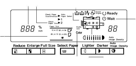
— LT/LDG Version —
1 |
2 |
3 |
4 |
5 6 |
7 |
8 9 10 |
|
|
|
|
|
|
|||||||||||||||
|
|
|
|
|
|
|
|
|
|
|
|
|
|
|
|
|
|
|
|
|
|
|
|
|
|
|
11 |
|
|
|
|
|
|
|
|
|
|
|
|
|
|
|
|
|
|
||||||||||
|
|
|
|
|
|
|
|
|
|
|
|
|
|
|
|
|
|
|
|
|
|
|
|
|
|
|
|
|
|
|
|
|
|
|
|
|
|
|
|
|
|
12 |
|||||||||||||
|
|
|
|
|
|
|
|
|
|
|
|
|
|
||||||||||||||
24 |
|
|
|
|
|
|
|
|
|
|
|
|
|
|
|
|
|
|
|
|
|
|
|
|
|
|
13 |
|
|
|
|
|
|
|
|
|
|
|
|
|
|
|
|
|
|
|
|
|
|
|
|||||
|
|
|
|
|
|
|
|
|
|
|
|
|
|
|
|||||||||||||
|
|
|
|
|
|
|
|
|
|
|
|
|
|
|
|
|
|
|
|
|
|
14 |
|||||
|
|
|
|
|
|
|
|
|
|
|
|
|
|
|
|
|
|
|
|
|
|
||||||
|
|
|
|
|
|
|
|
|
|
|
|
|
|
|
|||||||||||||
|
|
|
|
|
|
|
|
|
|
|
|
|
|
|
|
|
|
|
|
15 |
|||||||
|
|
|
|
|
|
|
|
|
|
|
|
|
|
||||||||||||||
|
|
|
|
|
|
|
|
|
|
|
|
|
|
|
|
|
|
||||||||||
|
|
|
|
|
|
|
|
|
|
|
|
|
|
|
|
|
|
|
|
|
|
|
|
|
|
|
|
|
|
|
|
|
|
|
|
|
|
|
|
|
|
|
|
|
|
|
|
|
|
|
|
|
|
|
|
|
|
|
|
|
|
|
|
|
|
|
|
|
|
|
|
|
|
|
|
|
|
|
|
|
|
|
|
23 |
22 |
21 |
20 19 18 |
17 |
16 |
12. Wait Indicator
Lights when that the machine is not ready to copy.
13. Copy Counter
Displays the number of copies entered. While copying, it shows the number of copies made.
14.Auto Image Density Indicator
Lights when the copier is automatically controlling image density. If this indicator blinks, refer to page 55.
15.Manual Image Density Indicator
Shows the manually selected image density. If this indicator blinks, refer to page 55.
16.Auto Image Density Key
Press to select/cancel the automatic image density mode.
17.Manual Image Density Keys
Use to cancel the automatic image density mode and manually select the image density level.
18.Misfeed Location Display
Shows the location(s) of misfed paper.
19.Color Copy Indicator
Lights if a color toner development unit is installed.
20. Select Paper Key
Press to select the cassette or the paper tray for paper feed, or press to cancel auto paper selection mode when the document feeder is installed.
21. Full Size Key
Press to make copies the same size as the originals.
22. Enlarge Key
Press to make enlarged copies.
23. Reduce Key
Press to make reduced copies.
24. Paper Size Indicator
Shows the size and direction of the paper in use.
1-6
1 June 1990
—Section C —
—A4/A3 Version —
5 |
4 |
6 |
7 |
3 |
|
|
|
|
|
|
|
|
|
|
|
|
|
|
|
|
|
8 |
|
|
|
|
|
|
|
|
|
|
|
|
|
|
|
|
|
||
2 |
|
|
|
|
|
|
|
|
|
|
|
|
|
|
|
|||
|
|
|
|
|
|
|
|
|
|
|
|
|
|
|
|
9 |
||
|
|
|
|
|
|
|
|
|
|
|
|
|
|
|||||
|
|
|
|
|
|
|
|
|
|
|
|
|
|
|
|
|||
|
|
|
|
|
|
|
|
|
|
|
|
|
|
|
|
|||
|
|
|
|
|
|
|
|
|
|
|
|
|
|
|
||||
|
|
|
|
|
|
|
|
|
|
|
|
|
||||||
|
|
|
|
|
|
|
|
|
|
|
|
|
|
|
|
|||
|
|
|
|
|
|
|
|
|
|
|
|
10 |
|
|
|
|
||
1 |
|
13 |
12 |
11 |
||||||||||||||
1. Sorter Key
Press to select the sort or stack mode. The sort mode and stack mode are optional features requiring a sorter.
2. Stack Indicator
Lights when in the stack mode.
3. Sort Indicator
Lights when in the sort mode.
4. Duplex Key
Press to select one of three duplex modes. These modes are optional features requiring a duplex unit.
5. Duplex Indicators
Show which duplex copying mode is selected.
6. Auto Reduce/Enlarge Indicator
Lights when in the auto reduce/enlarge mode. This mode is an optional feature requiring a document feeder.
1-7

1 June 1990
— LT/LDG Version —
5 |
4 |
6 |
7 |
3 |
|
|
|
|
|
|
|
|
|
|
|
|
|
|
|
|
8 |
|
|
|
|
|
|
|
|
|
|
|
|
|
|
|
|
||
|
|
|
|
|
|
|
|
|
|
|
|
|
|||||
2 |
|
|
|
|
|
|
|
|
|
|
|
|
|
|
|||
|
|
|
|
|
|
|
|
|
|
|
|
|
|
|
|
9 |
|
|
|
|
|
|
|
|
|
|
|
|
|
|
|||||
|
|
|
|
|
|
|
|
|
|
|
|
|
|
||||
|
|
|
|
|
|
|
|
|
|
|
|||||||
|
|
|
|
|
|||||||||||||
|
|
|
|
|
|
|
|
|
|
|
|
|
|||||
|
|
|
|
|
|
|
|
|
|
|
|
|
|
|
|
|
|
|
|
|
|
|
|
|
|
|
|
|
|
|
|
|
|
|
|
1 |
13 |
12 |
11 |
10 |
7.Auto Reduce/Enlarge Key
Press to select the auto reduce/enlarge mode. This mode is an optional feature requiring a document feeder.
8.Zoom Up Key
Press to increase the reproduction ratio in 1% steps.
9.Zoom Down Key
Press to reduce the reproduction ratio in 1% steps.
10.Size Magnification Key
Press to select the size magnification mode.
11.Size Magnification Indicators
Lights when in the size magnification mode; shows when to enter the original size and copy size data.
12.2 Single Copies Key
Press to select one of two 2 single copies modes. The 2 Sided Original mode is an optional feature requiring a document feeder.
13. 2 Single Copies Indicators
Show which the 2 single copies mode is selected.
1-8
1 June 1990
1-9
1 June 1990
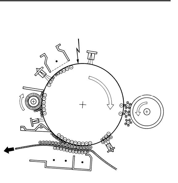
3.COPY PROCESSES AROUND THE DRUM
2.EXPOSURE
1.DRUM CHARGE
3. ERASE
9. QUENCHING
4. DEVELOPMENT
8. CLEANING
5. PRE-TRANSFER LAMP (PTL)
7. PAPER |
6. IMAGE TRANSFER |
|
SEPARATION |
||
|
1-10
1 June 1990
1. DRUM CHARGE
In the dark, the charge corona unit gives a uniform negative charge to the organic photoconductive (OPC) drum. The charge remains on the surface of the drum because the OPC drum has a high electrical resistance in the dark.
2. EXPOSURE
An image of the original is reflected to the OPC drum surface via the optics assembly. The charge on the drum surface is dissipated in direct proportion to the intensity of the reflected light, thus producing an electrical latent image on the drum surface.
3. ERASE
The erase lamp illuminates the areas of the charged drum surface that will not be used for the copy image. The resistance of the drum in the illuminated areas drops and the charge on those areas dissipates.
4. DEVELOPMENT
Positively charged toner is attracted to the negatively charged areas of the drum, thus developing the latent image. (The positive triboelectric charge is caused by friction between the carrier and toner particles.)
5. PRE-TRANSFER LAMP (PTL)
The PTL illuminates the drum to remove all negative charge from the exposed areas of the drum. This prevents the toner particles from being reattracted to the drum surface during paper separation and makes paper separation easier.
6. IMAGE TRANSFER
Paper is fed to the drum surface at the proper time so as to align the copy paper and the developed image on the drum surface. Then, a strong negative charge is applied to the back side of the copy paper, producing an electrical force which pulls the toner particles from the drum surface to the copy paper. At the same time, the copy paper is electrically attracted to the drum surface.
7. PAPER SEPARATION
A strong ac corona discharge is applied to the back side of the copy paper, reducing the negative charge on the copy paper and breaking the electrical attraction between the paper and the drum. Then, the stiffness of the copy paper causes it to separate from the drum surface. The pick-off pawls help to separate paper.
8. CLEANING
The cleaning brush removes most of the toner on the drum and loosens the remainder. Then the cleaning blade scrapes off the loosened toner.
9. QUENCHING
Light from the quenching lamp electrically neutralizes the surface of the drum.
1-11

1 June 1990
4. FUNCTIONAL OPERATION
1-12

1 June 1990
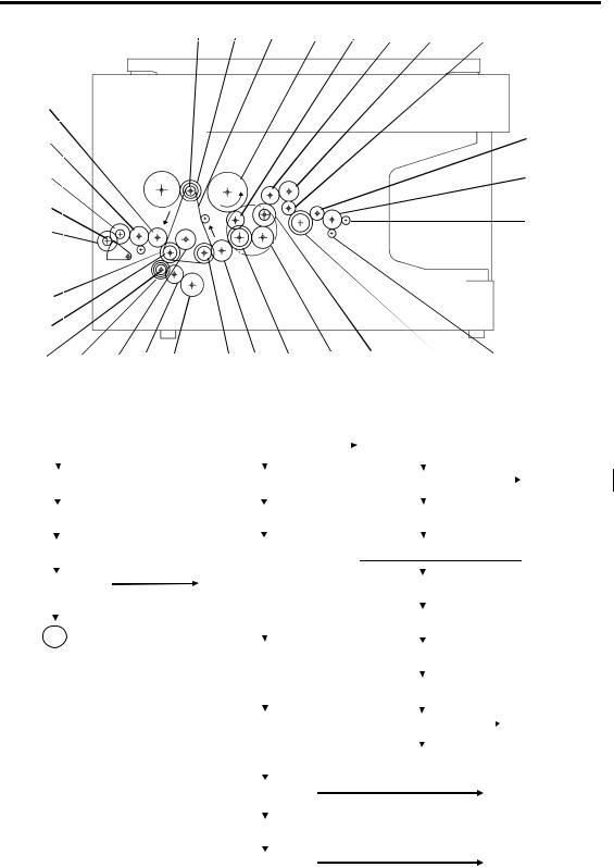
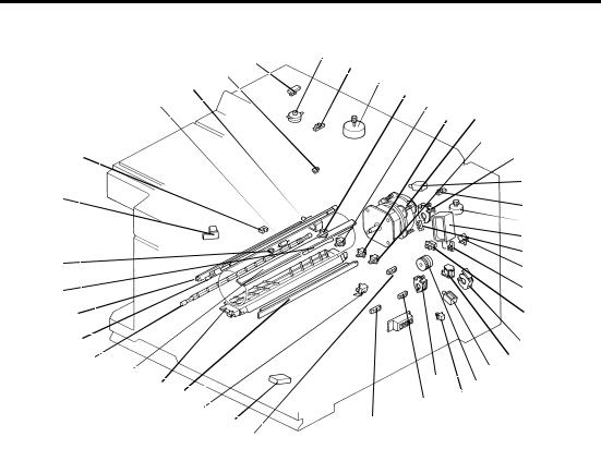
5. MECHANICAL COMPONENT LAYOUT
1 |
2 |
3 |
4 |
5 |
|
6 |
7 |
8 |
|
9 |
10 |
11 |
12 |
13 |
14 |
|
|
|
|
|
|
|
|
|
|
|
|
|
|
|
15 |
|
|
|
|
|
|
|
|
|
|
|
|
|
|
|
16 |
33 |
|
|
|
|
|
|
|
|
|
|
|
|
|
|
17 |
32 |
|
|
|
|
|
|
|
|
|
|
|
|
|
|
18 |
|
|
|
|
|
|
|
|
|
|
|
|
|
|
|
|
31 |
|
|
|
|
|
|
|
|
|
|
|
|
|
|
|
30 |
|
|
|
|
|
|
|
|
|
|
|
|
|
|
|
|
|
|
|
|
|
|
|
|
|
|
|
|
|
|
19 |
|
|
29 |
28 |
27 |
26 |
25 |
24 |
23 |
22 |
21 |
20 |
|
|
|
|
1. |
Third Mirror |
19. |
Separation Roller |
2. |
Second Mirror |
20. |
Relay Rollers |
3. |
First Mirror |
21. |
Semi-circular Feed Rollers |
4. |
Exposure Lamp |
22. |
Registration Rollers |
5. |
Ozone Filter |
23. |
Pre-transfer Lamp (PTL) |
6. |
Cleaning Unit |
24. |
Transfer and Separation Corona |
7. |
Lens |
|
Unit |
8. |
Quenching Lamp (QL) |
25. |
Pick-off Pawls |
9. |
Charge Corona Unit |
26. |
Cleaning Brush |
10. |
Sixth Mirror |
27. |
Cleaning Blade |
11. |
Erase lamp (EL) |
28. |
Pressure Roller |
12. |
OPC Drum |
29. |
Hot Roller |
13. |
Development Unit |
30. |
Duplex Turn Guide (Option) |
14. |
Toner Supply Unit |
31. |
Exit Rollers |
15. |
Optics Cooling Fans |
32. |
Hot Roller Strippers |
16. |
Feed Roller |
33. |
Exhaust Blower |
17.Manual Feed Table
18.Pick-up Roller
1-13
1 June 1990
6. DRIVE LAYOUT
|
|
G17 BP2 G16 |
TB1 G19 G18 G22 |
G23 |
G24 |
|||
G5 |
|
|
|
|
|
|
||
G6 |
|
|
|
|
|
G26 |
||
|
|
|
|
|
|
|||
G7 |
|
|
|
|
|
G27 |
||
|
|
|
||||||
G9 |
|
|
|
|||||
G8 |
|
|
G28 |
|||||
|
|
|
||||||
G10 |
|
|
|
|
|
|||
|
|
|
|
|||||
G4 |
|
|
|
|
||||
BP3 |
|
|
|
|
||||
|
|
|
|
|
|
|
||
G13 G12 G11 G14 G15 BP1G3 G2 |
G1 G20 G21 |
G25 |
G29 |
|||||
G1: Main Motor Gear |
|
|
|
|
|
|
|
G20: Relay Gear |
|
|
|
|
||||||
|
|
|
|
|
|
|
|
|
|
|||||||||
|
|
|
|
|
|
|
|
|
|
|
|
|
|
|
|
|
|
|
|
|
|
|
|
|
|
|
|
||||||||||
G2: Relay Gear |
G18: Relay Gear |
|
G21: Cleaning Drive |
|
|
|
Cleaning Unit |
|
||||||||||
|
|
|||||||||||||||||
|
|
|
|
|
|
|
|
|
|
|
|
|
|
|
|
|
|
|
|
|
|
|
|
|
|
|
|
|
|
|
|
|
|
|
|
|
|
G3: Timing Belt Drive Gear |
G19: Drum Drive Gear |
|
G22: Relay Gear |
|
|
|
|
|||||||||||
|
|
|
|
|
|
|
|
|
|
|
|
|
|
|
|
|
|
|
|
|
|
|
|
|
|
|
|||||||||||
BP1: Timing Belt Pulley |
|
Drum |
|
|
Fusing and Exit Section |
|
|
|||||||||||
|
|
|
|
|
|
|
|
|
|
|
|
|
|
|
|
|
|
|
|
|
|
|
|
|
|
|
|
|
|
||||||||
TB1: Timing Belt |
Development |
|
|
G23: Relay Gear |
|
|
|
|
||||||||||
|
|
|
|
Section |
|
|
|
|
|
|
|
|
|
|
|
|
||
|
|
|
|
|
|
|
|
|
|
|
|
|
|
|||||
|
|
|
|
G24: Relay Gear |
|
|
|
|
||||||||||
|
|
|
|
|
|
|
|
|
|
|
|
|
||||||
A |
|
|
|
|
|
|
|
|
|
|||||||||
|
|
|
|
|
|
|
|
|
|
|
|
|
|
|
|
|||
BP2: Timing Belt |
|
G25: Hot Roller Gear |
|
|
|
|
||||||||||||
|
|
|
|
|
|
|
|
|||||||||||
|
|
|
|
Pulley |
|
|
|
|
|
|
|
|
|
|
|
|||
|
|
|
|
G26: Relay Gear |
|
|
|
|
||||||||||
|
|
|
|
|
|
|
|
|
|
|
|
|
||||||
|
|
|
|
|
|
|
|
|
|
|
|
|||||||
|
|
|
|
|
|
|
|
|
|
|
|
|
|
|
|
|
|
|
|
|
|
|
|
|
|
|
|
|
|
|
|
|
|
|
|
|
|
|
|
|
G16: Development |
|
G27: Relay Gear |
|
|
|
G29: Duplex Transp |
|||||||||
|
|
|
|
|
||||||||||||||
|
|
|
|
CL Gear |
|
|
|
|
|
|
|
|
|
Gear (Option) |
||||
|
|
|
|
G28: Exit Roller Gear |
||||||||||||||
|
|
|
|
|
|
|
|
|
|
|
|
|
||||||
|
|
|
|
|
|
|
|
|
|
|
|
|||||||
|
|
|
|
|
|
|
|
|
|
|
|
|
|
|
|
|
|
|
|
|
|
|
|
|
|
|
|
|
|
|
|
|
|||||
|
|
|
Development CL |
|
|
|
|
Development Unit |
|
|||||||||
|
|
|
|
|
|
|
|
|
|
|
|
|
|
|
|
|
||
|
|
|
|
|
|
|
|
|
|
|
|
|
|
|
|
|
|
|
|
|
|
G17: Toner Supply CL Gear |
|
|
|
|
|||||||||||
|
|
|
|
|
|
|
|
|
|
|
|
|
|
|
|
|
|
|
|
|
|
|
|
|
|
|
|
|
|
|
|
|
|||||
|
|
|
Toner Supply CL |
|
|
|
|
Toner Supply Unit |
|
|||||||||
|
|
|
|
|
|
|
|
|
|
|
|
|
|
|
|
|
|
|
1-14
|
|
|
|
|
|
|
|
|
|
|
1 June 1990 |
|
|
|
|
|
|
|
|
A |
|
|
|
||
|
|
|
|
|
|
|
|
|
|
|
||
|
|
|
|
|
|
Paper Feed Section |
|
|
|
|
||
|
|
|
|
|
|
|
|
|
|
|
|
|
|
|
|
|
|
|
|
|
|
|
|
|
|
|
|
|
|
|
|
BP3: Timing Belt Pulley |
|
|
|
|||
|
|
|
|
|
|
|
|
|
|
|
|
|
|
|
|
|
|
|
|
|
|
|
|
|
|
G11: Registration CL Gear |
|
|
G4: Relay Gear |
|
|
|
2nd Feed Station |
|
||||
|
|
|
|
|
|
|||||||
|
|
|
||||||||||
|
|
|
|
|
|
|
|
|||||
Registration CL |
|
|
G5: Relay Gear |
|
G12: Relay Roller |
|||||||
|
|
|
|
|
|
|
|
|
|
|
CL Gear |
|
|
|
|
|
|
|
|
|
|
|
|||
Registration Roller |
|
|
|
|
|
|
||||||
|
|
|
|
|
|
|
|
|
||||
|
|
|
|
|
|
|
|
|
|
|
|
|
|
|
|
|
|
G6: 1st Paper Feed CL Gear |
|
Relay Roller CL |
|||||
1st Paper Feed CL |
|
|
|
|
|
|||||||
|
|
|
|
|||||||||
|
|
|
|
|
|
|
|
|
|
|
||
1st Paper Feed CL |
|
|
G7: Relay Gear |
|
Relay Roller |
|||||||
|
|
|
|
|
|
|
|
|
|
|
G13: Relay Roller Gear |
|
1st Paper Feed Rollers |
|
|
G8: Paper Lift CL Gear |
|
G14: Relay Gear |
|||||||
|
|
|
|
|
|
|
|
|
|
|
G15: 2nd Paper Feed |
|
|
|
|
|
|
|
Paper Lift CL |
|
|
CL Gea |
|||
|
|
|
|
|
|
|
|
|
|
|||
|
|
|
|
|
|
|
|
|
|
|
||
|
|
|
|
|
|
G9: Paper Lift Gear |
|
2nd Paper Feed CL |
||||
|
|
|
|
|
|
G10: Sector Gear |
|
2nd Paper Feed Roller |
||||
1-15
1 June 1990
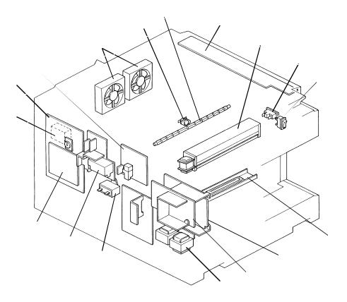
7. ELECTRICAL COMPONENT LAYOUT
|
|
|
|
|
2 |
|
|
|
|
|
|
|
|
|
4 |
1 |
|
3 |
5 |
|
|
|
|
|
|
|
43 |
|
|
|
6 |
|
|
||
|
|
42 |
|
|
|
|
7 |
|
10 |
||
|
|
|
|
|
|
8 |
|
||||
|
|
|
|
|
|
|
|
|
|
|
9 |
|
40 |
|
|
|
|
|
|
|
|
|
13 |
|
39 |
|
|
|
|
|
|
|
|
|
11 |
|
|
|
|
|
|
|
|
|
|
12 |
|
|
|
|
|
|
|
|
|
|
|
|
|
|
|
|
|
|
|
|
|
|
|
|
15 |
|
|
|
|
|
|
|
|
|
|
|
16 |
|
41 |
|
|
|
|
|
|
|
|
|
14 |
|
|
|
|
|
|
|
|
|
|
17 |
|
|
32 |
|
|
|
|
|
|
|
|
|
18 |
|
38 |
|
|
|
|
|
|
|
|
|
19 |
|
|
|
|
|
|
|
|
|
|
||
|
36 |
|
|
|
|
|
|
|
|
|
20 |
|
37 |
|
|
|
|
|
|
|
|
|
2221 |
|
34 |
35 |
31 |
|
|
|
|
|
25 |
|
24 |
|
|
|
|
|
|
|
|
27 |
23 |
||
|
|
|
30 |
33 |
|
|
|
|
|
|
|
|
|
|
|
|
|
|
|
||||
|
|
|
|
|
|
29 26 |
|
|
|||
|
|
|
|
28 |
|
|
|
|
|
|
|
1. |
Scanner H.P. Sensor |
|
|
22. |
Relay Roller CL Sol. |
|
|
||||
2. |
Lens Motor |
|
|
|
23. |
Right Cover SW |
|
|
|||
3. |
Lens H.P. Sensor |
|
|
|
24. |
Registration Clutch |
|
|
|||
4. |
Exit Sensor |
|
|
|
25. |
2nd Paper Feed CL Sol. |
|||||
5. |
Scanner Motor |
|
|
|
26. |
1st Paper Size SW |
|
|
|||
6. |
2nd Paper Size SW-1 (SW4) |
|
27. |
1st Paper End Sensor |
|
||||||
7. |
2nd Paper Size SW-2 (SW5) |
|
28. |
2nd Paper End Sensor |
|
||||||
8. |
2nd Paper Size SW-3 (SW6) |
|
29. |
Cassette Lift Sensor |
|
|
|||||
9. |
2nd Paper Size SW-4 (SW7) |
|
30. |
Registration Sensor |
|
|
|||||
10. |
Main Motor |
|
|
|
31. |
Pre-transfer Lamp (PTL) |
|||||
11. |
Development CL Sol. |
|
|
32. |
ID Sensor |
|
|
||||
12. |
4th/5th Mirror H.P. Sensor |
|
33. |
Total Counter |
|
|
|||||
13. |
Toner Supply CL Sol. |
|
|
34. |
Erase Lamp (EL) |
|
|
||||
14. |
Toner End Sensor |
|
|
35. |
Transfer and Separation Corona Unit |
||||||
15. |
4th/5th Mirror Motor |
|
|
36. |
Charge Corona Unit |
|
|
||||
16. |
Pick-up Roller Release Sol. |
|
37. |
Fusing Lamp |
|
|
|||||
17. |
Manual Feed Table SW |
|
38. |
Quenching Lamp (QL) |
|
||||||
18. |
Development Unit Set Sensor |
|
39. |
Auto ID Sensor |
|
|
|||||
19. |
Color Switch |
|
|
|
40. |
Toner Overflow Sensor |
|||||
20. |
Paper Lift CL Sol. |
|
|
|
41. |
Fusing Thermistor |
|
|
|||
21. |
1st Paper Feed CL Sol. |
|
42. |
Fusing Thermofuse |
|
|
|||||
|
|
|
|
|
43. |
Tray Lock Sol. |
|
|
|||
1-16
1 June 1990
|
49 |
|
50 |
|
48 |
|
51 |
|
47 |
|
52 |
|
46 |
45 |
53 |
|
|
44 |
|
|
62 |
|
|
|
54 |
|
|
|
|
||
|
61 |
|
|
|
|
|
|
|
|
55 |
|
|
60 |
|
|
|
|
|
|
|
|
|
56 |
|
59 |
|
|
||
|
58 |
|
57 |
||
44. |
Key Counter (Option) |
54. |
Drum Anti-condensation Heater |
||
45. |
Main Board |
55. |
Main DC Power Supply Board |
||
46. |
CC/Grid/Bias Power Pack |
56. |
Optional DC Power Supply Board |
||
47. |
Optics Cooling Fan Motors |
|
(Option) |
||
48. |
Optics Thermoswitch |
57. |
Optional Transformer (Option) |
||
49. |
Exposure Lamp |
58. |
Main Transformer |
||
50. |
Operation Panel Board |
59. |
AC Drive Board |
||
51. |
Exhaust Blower Motor |
60. |
Main Motor Capacitor |
||
52. |
Cover Safety SW |
61. |
TC/SC Power Pack |
||
53. |
Main SW |
62. |
Interface Board (Option) |
||
1-17

1 June 1990
8. ELECTRICAL COMPONENT DESCRIPTIONS
SYMBOL |
NAME |
FUNCTION |
INDEX |
Motors |
|
|
NO. |
|
|
|
|
M1 |
Main Motor |
Drives all the main unit components except |
10 |
|
|
for the optics unit and fans. |
|
|
|
(115/220/240Vac) |
|
M2 |
Scanner Motor |
Drives the scanners (1st and 2nd). (dc |
5 |
|
|
stepper) |
|
M3 |
Lens Motor |
Moves the lens position according to the |
2 |
|
|
selected magnification. (dc stepper) |
|
M4 |
4th/5th Mirror Mo- |
Move the 4th/5th mirror position according |
15 |
|
tor |
to the selected magnification. (dc stepper) |
|
M5 |
Optics Cooling |
Prevents built up of hot air in the optics |
47 |
|
Fan Motor-1 |
cavity. (24 Vdc) |
|
M6 |
Optics Cooling |
Prevents built up of hot air in the optics |
47 |
|
Fan Motor-2 |
cavity. (24 Vdc) |
|
M7 |
Exhaust Blower |
Removes heat from around the fusing unit |
51 |
|
Motor |
and blower the ozone built up around the |
|
|
|
charge section to the ozone filter. |
|
Magnetic Clutch |
|
|
|
MC1 |
Registration |
Drives the registration roller. |
24 |
|
Clutch |
|
|
Solenoid |
|
|
|
SOL1 |
Toner Supply |
Drives the toner supply roller via the toner |
13 |
|
Clutch Solenoid |
supply spring clutch. |
|
SOL2 |
1st Paper Feed |
Starts paper feed from the first paper |
21 |
|
Clutch Solenoid |
station. |
|
SOL3 |
2nd Paper Feed |
Starts paper feed from the 2nd paper |
25 |
|
Clutch Solenoid |
station. |
|
SOL4 |
Pick-up Roller |
a) After the paper is fed, releases the |
16 |
|
Release Solenoid |
pick-up roller from next paper. b) When the |
|
|
|
manual feed table is used, releases the |
|
|
|
pick-up roller from the table. |
|
SOL5 |
Paper Lift Clutch |
Lifts paper to the appropriate feed position. |
20 |
|
Solenoid |
|
|
SOL6 |
Tray Lock Sole- |
Locks the paper tray/duplex unit. |
43 |
|
noid |
|
|
SOL7 |
Development |
Drives the development unit. |
11 |
|
Clutch Solenoid |
|
|
SOL8 |
Relay Roller |
Drives the relay roller for the 2nd cassette |
22 |
|
Clutch Solenoid |
station. |
|
1-18
SYMBOL |
NAME |
FUNCTION |
Switches |
|
|
SW1 |
Main Switch |
Supplies power to the copier. |
SW2 |
Cover Safety |
Cuts the ac power line. |
|
Switch |
|
SW3 |
1st Paper Size |
Determines what size paper is in the first |
|
Switch |
cassette. |
SW4 |
2nd Paper Size |
Determines what size paper is in the paper |
|
Switch-1 |
tray. |
SW5 |
2nd Paper Size |
Determines what size paper is in the paper |
|
Switch-2 |
tray. |
SW6 |
2nd Paper Size |
Determines what size paper is in the paper |
|
Switch-3 |
tray. |
SW7 |
2nd Paper Size |
Determines what size paper is in the paper |
|
Switch-4 |
tray. |
SW8 |
Color Switch |
Determines which color development unit is |
|
|
installed. |
SW9 |
Manual Feed Ta- |
Detects when the manual feed table is |
|
ble Switch |
open. |
SW10 |
Right Cover |
Detects when the right cover is open. |
|
Switch |
|
Sensor |
|
|
S1 |
Scanner Home |
Informs the CPU when the 1st scanner is at |
|
Position Sensor |
the home position. |
S2 |
Lens Home |
Informs the CPU when the lens is at the |
|
Position Sensor |
home position (full size position). |
S3 |
4th/5th Mirror |
Informs the CPU when the 3rd scanner |
|
Home Position |
(4th/5th mirrors assembly) is at the home |
|
Sensor |
position (full size position). |
S4 |
Registration |
Detects misfeeds. |
|
Sensor |
|
S5 |
Exit Sensor |
Detects misfeeds. |
S6 |
1st Paper End |
Informs CPU when the first cassette runs |
|
Sensor |
out of paper. |
S7 |
2nd Paper End |
Informs CPU when the paper tray runs out |
|
Sensor |
of paper. |
S8 |
Toner End |
Detects when it is time to add toner. |
|
Sensor |
|
S9 |
Toner Overflow |
Detects when the used toner tank is full. |
|
Sensor |
|
S10 |
Paper Lift |
Detects the correct feed height of the |
|
Sensor |
cassette. |
1 June 1990
INDEX
NO.
53
52
26
6
7
8
9
19
17
23
1
3
12
30
4
27
28
18
40
29
1-19
1 June 1990 |
|
|
|
SYMBOL |
NAME |
FUNCTION |
INDEX |
|
|
|
NO. |
S11 |
Image Density |
Detects the density of the image on the |
32 |
|
(ID) Sensor |
drum to control the toner density. |
|
S12 |
Development |
Sensors whether or not the development |
18 |
|
Unit Set Sensor |
unit is properly set. |
|
Printed Circuit Board |
|
|
|
PCB1 |
Main Board |
Controls all copier functions both directly |
45 |
|
|
and through the other PCBs. |
|
PCB2 |
AC Drive Board |
Drives all ac motors, the exposure lamp, |
59 |
|
|
fusing lamp, quenching lamp, exhaust |
|
|
|
blower motor. |
|
PCB3 |
Main DC Power |
Rectifies 26 and 10 Vac input and outputs |
55 |
|
Supply Board |
dc voltages. |
|
PCB4 |
Auto Image |
Senses the background density of the |
39 |
|
Density Sensor |
original. |
|
|
(ADS) |
|
|
PCB5 |
Optional DC |
Rectifies 26 and 10 Vac input and outputs |
56 |
|
Power Supply |
dc voltasges. |
|
|
Board |
|
|
PCB6 |
Interface Board |
Interfaces between the copier main board |
62 |
|
|
and all the optional equipment’s main board. |
|
PCB7 |
Operation Panel |
Informs the CPU of the selected modes |
50 |
|
Board |
and displays the situations on the panel. |
|
Lamps |
|
|
|
L1 |
Exposure Lamp |
Applies high intensity light to the original for |
49 |
|
|
exposure. |
|
L2 |
Fusing Lamp |
Provides heat to the hot roller. |
37 |
L3 |
Quenching Lamp |
Neutralizes any charge remaining on the |
38 |
|
|
drum surface after cleaning. |
|
L4 |
Erase Lamp |
Discharge the drum outside of the image |
34 |
|
|
area. Provides leading/trailing edge erase. |
|
L5 |
Pre-transfer |
Reduces charge on the drum surface |
31 |
|
Lamp |
before transfer. |
|
Power Packs |
|
|
|
P1 |
CC/Grid/Bias |
Provides high voltage for the charge |
46 |
|
Power Pack |
corona, grid, and the development roller |
|
|
|
bias. |
|
P2 |
TC/SC Power |
Provides high voltage for the transfer and |
61 |
|
Pack |
separation corona. |
|
1-20
|
|
|
1 June 1990 |
SYMBOL |
NAME |
FUNCTION |
INDEX |
Heaters |
|
|
NO. |
|
|
|
|
H1 |
Drum Anti- |
Prevents moisture around the drum. |
54 |
|
condensation |
|
|
|
Heater |
|
|
H2 |
Optics Anti-con- |
Prevents moisture from forming on the |
N/A |
|
densation Heater |
optics. |
|
|
Option |
|
|
Counters |
|
|
|
CO1 |
Total Counter |
Keeps track of the total number of copies |
33 |
|
|
made. |
|
CO2 |
Key Counter |
Used for control of authorized use. Copier |
44 |
|
(Option) |
will not operate until installed. |
|
Transformer |
|
|
|
TR1 |
Main Transformer |
Steps down the wall voltage to 26 Vac and |
58 |
|
|
10 Vac. |
|
TR2 |
Optional |
Steps down the wall voltage to 26 Vac and |
57 |
|
Transformer |
10 Vac for the document feeder and duplex |
|
|
|
unit. |
|
Others |
|
|
|
TH |
Fusing |
Monitors the fusing temperature. |
41 |
|
Thermistor |
|
|
TF |
Fusing |
Provides back-up overheat protection in the |
42 |
|
Thermofuse |
fusing unit. |
|
TS |
Optics |
Provides back-up overheat protection |
48 |
|
Thermoswitch |
around the exposure lamp. |
|
C |
Main Motor Ca- |
Start capacitor |
60 |
|
pacitor |
|
|
1-21
1 June 1990
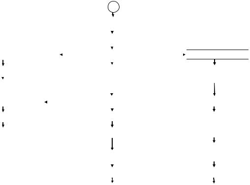
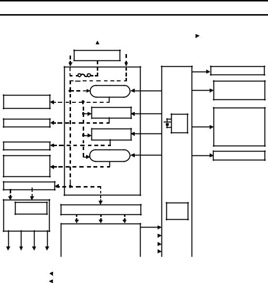
9. OVERALL MACHINE CONTROL
|
|
|
|
AC Power (115V or 220/240V) |
|
|
|
|
|
|
|||||||
|
|
|
|
|
|
|
|
|
|
|
|
|
|
|
|
|
|
|
|
|
|
|
Cover Safety Switch |
|
|
|
|
|
|
|
|||||
|
|
|
|
|
|
|
|
|
|
|
|
|
|
|
|
|
|
|
|
|
|
|
|
|
|
|
|
|
|
|
|
|
|
Anti-condensation Heater |
|
|
|
|
|
|
|
Main Switch |
|
|
|
|
|
|
-Drum |
|
|||
|
|
|
|
|
|
|
|
|
|
|
|
|
|
|
|
-Optics |
|
|
|
Operation |
|
|
|
|
|
|
|
|
|
|
|
|
|
|
|
|
|
|
|
|
|
|
|
|
|
|
|
|
|
|
|
|
|
|
|
Panel Board |
|
|
|
|
|
|
|
|
|
|
|
|
|
Sensors/Switches/Thermistor |
|
|
|
|
|
|
|
|
|
|
|
|
|
|
|
|
|
||
|
|
|
|
|
|
|
|
|
|
|
|
|
IC 123 |
|
Image Density Sensor |
|
|
|
|
|
|
|
|
|
|
|
|
|
|
|
|||||
|
|
|
|
|
|
AC Drive Board |
|
|
CPU |
|
Registration Sensor |
|
|||||
|
|
|
|
|
|
|
|
|
|
|
|
|
|
|
|
Cassette Lift Sensor |
|
|
|
|
|
|
|
|
|
|
|
|
|
|
|
|
|
|
|
|
|
|
|
|
|
|
|
|
|
|
|
|
|
|
|
Exit Sensor |
|
|
|
Exhaust Blower Motor (L) |
|
|
Power Relay |
|
|
|
IC 105 |
|
|
Auto ID Sensor |
|
||||
|
|
|
|
|
|
|
|
|
|
|
|
|
|
|
|
||
|
|
|
|
|
|
|
|
|
|
|
|
|
|
Scanner HP Sensor |
|
||
|
|
|
|
|
|
|
|
|
|
|
|
|
I/O |
|
|
||
|
|
|
|
|
|
Fusing Lamp |
|
|
|
|
|
|
Lens HP Sensor |
|
|||
|
|
Fusing Lamp |
|
|
Drive Circuit |
|
|
|
|
|
|
4th/5th Mirror HP Sensor |
|
||||
|
|
|
|
|
|
|
|
|
|
|
|
|
IC 124 |
|
|
Toner Overflow Sensor |
|
|
|
|
|
|
|
Exposure Lamp |
|
|
|
|
Toner End Sensor |
|
|||||
|
|
Exposure Lamp |
|
||||||||||||||
|
|
|
|
Drive Circuit |
|
|
|
I/O |
|
Color Switch |
|
||||||
|
|
|
|
|
|||||||||||||
|
|
Main Motor |
|
|
|
|
|
|
|
|
|
|
|
|
1st/2nd Paper Size Switches |
|
|
|
|
Quenching Lamp |
|
|
Main Motor Relay |
|
|
|
|
IC 111 |
|
|
1st/2nd Paper End Sensors |
|
|||
|
|
|
|
|
|
|
|
|
Right Cover Switch |
|
|||||||
|
|
Exhaust Blower Motor (H) |
|
|
|
|
|
|
|
|
|
|
|
||||
|
|
|
|
|
|
|
|
|
|
|
ROM |
|
|
Manual Feed Table Switch |
|
||
|
|
|
|
|
|
|
|
|
|
|
|
|
|
|
|
Fusing Thermistor |
|
|
|
|
|
|
|
|
|
|
|
|
|
|
|
|
|
|
|
Power Packs |
|
Solenoids/Clutches |
|
CC/Grid/Bias P.P. |
|
||
Main Board |
Pick-up Roller Release Sol. |
||
Charge Corona |
Cassette Lift CL Sol. |
||
|
|||
Grid Voltage |
|
1st/2nd Paper Feed CL Sol. |
|
|
Relay Roller CL Sol. |
||
Dev. Bias |
|
||
|
Registration Clutch |
||
|
RAM |
Tray Lock Sol. |
|
TC/SC P.P. |
Development Drive CL Sol. |
||
Board |
|||
|
Toner Supply CL Sol. |
||
|
|
Counters |
Motors |
|
|
|
Scanner Motor |
|
Total Counter |
Lens Motor |
|
|
4th/5th Mirror |
|
Key Counter |
Optics Cooling Fan Motor |
ARDF |
Serial |
|
NOTE: The interface board is |
|
Interface |
connected to the copier main |
|||
Duplex |
Serial |
|||
Board |
board when the ARDF, duplex |
|||
Sorter |
|
|
||
|
|
unit and/or sorter is installed. |
||
|
|
|
The above diagram shows the control system of this copier in block form. The CPU (IC123) on the main board controls the timing of all copier’s operation based on the CPU’s internal clock. The CPU monitors the input signals from all sensors and controls the dc components directly or through two I/O chips (IC 105 and IC 124). It also controls ac components such as the fusing lamp, exposure lamp, main motor quenching lamp, and exhaust blower motor (High speed) directly via the ac drive board. The exhaust blower motor (Low speed) is controlled via the I/O chip (IC 124) and ac drive board. The charge corona, grid voltage and development bias are powered by the same power pack (P1) but are controlled separately as shown above. The main board has a
RAM board for the service program mode and misfeed recovery. A battery backs up the power to the RAM board.
1-22
1 June 1990
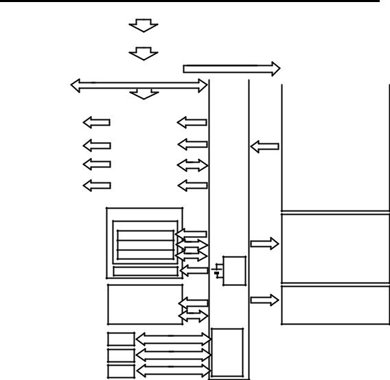
10. AC POWER AND DC POWER
DISTRIBUTION
AC Power (115V or 220/240V)
|
|
|
Main SW |
|
|
|
|
|
|
|
|
|
|
|
|
|
|
|
|
|
|
|
|
Anti-condensation Heater |
||
|
|
|
|
|
|
|
|
|
|
|
|
|
|
|
|
|
|
|
|
|
|
|
||||
|
|
|
|
|
|
|
|
|
|
|
|
|
|
|
|
|
|
|
|
|
|
|
|
|
|
-Drum |
|
|
|
|
|
|
|
|
|
|
|
|
|
|
|
|
|
|
|
|
|
|
|
|
|
|
|
|
|
|
|
|
|
|
|
|
|
|
|
|
|
|
|
|
|
|
|
|
|
|
|
|
|
-Optics (Option) |
Cover Safety SW
|
Fuse |
|
|
|
Scan |
Operation Panel Board |
|
|
|
|
|
|
Signal |
|
|
|
Power Relay |
|
24V (VA) |
5V (VC) |
|
Sensors |
|
|
|
|
|
|
Switches |
||
Exhaust Blower |
|
(RA401) |
|
|
|
|
Interface Board |
|
|
|
|
|
|
|
|
Motor (L) |
|
|
|
|
|
|
|
|
Fusing Lamp |
|
24V (VA) |
|
|
Solenoids |
|
|
|
Drive Circuit |
|
|
|
|
Clutches |
Fusing Lamp |
|
|
|
RAM |
24V (VA) |
Power Packs |
|
|
|
|
|
PCB |
Lens Motor |
||
|
Exposure Lamp |
24V (VA) |
|
|
4th/5th Mirror Motor |
||
|
|
Drive Circuit |
|
|
|
|
Optics Cooling Fan |
Exposure Lamp |
|
|
|
|
|
|
Motors |
|
|
|
24V (VA) |
30V (VM) |
|
||
|
Main Motor |
|
Scanner Motor |
||||
Main Motor |
Relay (RA402) |
Main |
|
|
|||
|
|
|
|||||
Quenching Lamp |
|
|
|
Board |
|
|
|
Exhaust Blower |
|
|
|
|
|
|
|
Motor (H) |
AC Drive Board |
|
|
|
|
|
|
|
|
|
|
|
|
||
Optional Transformer |
|
|
|
|
|
|
|
26V AC 10V AC |
|
|
|
|
|
|
|
FU100 (5V) |
Main Transformer |
|
Interface |
|
|
|
|
FU101 (24V) |
|
|
|
|
|||
|
|
|
Board |
|
|
|
|
Optional |
|
|
|
|
|
|
|
10V AC |
26V AC |
26V AC |
|
|
|
||
DC Power Supply |
|
|
|
30V (VM) |
|
|
|
Board |
Main DC Power Supply Board |
24V (VA) |
|
|
|
||
|
|
|
|
||||
24V |
5V |
24V |
5V |
|
|
|
|
|
|
|
|
|
|
|
|
|
|
|
|
|
||||
5V (VC) |
|
|
|
|
|
|
|
|
|
|
|
|||||||||||||
(VA) (VC) |
(VA) (VC) |
FU100 (5V) |
|
|
|
|
|
|
|
|
|
|
|
|
|
ac power |
||||||||
|
|
|
|
|
|
|
|
FU101 (24V) |
|
|
|
Zero |
|
|
|
|
|
|
|
|
|
|
|
|
|
|
|
|
|
|
|
|
|
|
|
|
|
|
|
|
|
|
|
|
|||||
|
|
|
|
|
|
|
|
|
|
|
|
|
|
|
|
|
|
|
|
|
|
|||
|
|
|
|
|
|
|
|
FU102 (30V) |
|
|
|
|
|
|
|
|
|
|
|
|
|
dc power |
||
ARDF |
|
|
Duplex |
|
|
|
|
|
|
|
Cross |
|
|
|
|
|
|
|
|
|
|
|||
|
|
|
24V (VA) |
|
|
|
|
|
|
|
|
|
|
|
|
|
|
|
||||||
|
|
|
|
|
|
|
|
|
|
|
|
|
|
|
|
|
|
|
|
|
||||
|
|
|
|
|
|
|
|
|
|
|
|
|
|
|
|
|
|
|
|
|
||||
|
|
|
|
Sorter |
|
|
|
|
|
|
|
|
|
|
|
|
|
|||||||
|
|
|
|
|
5V (VC) |
|
|
|
|
|
|
|
|
|
|
|
|
|
|
|||||
|
|
|
|
|
|
|
|
|
|
|
|
|
|
|
|
|
|
|
|
|
|
|
|
|
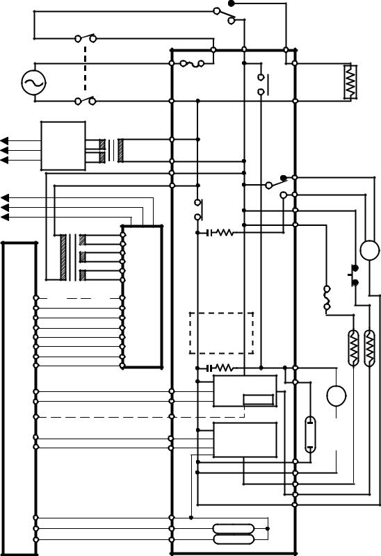
When this copier is plugged in and the main switch is turned off, ac power is supplied via the ac drive board to the anti-condensation heater. When the front cover and/or the exit cover is open, the cover safety switch completely cuts off power to all ac and dc components. The RAM board has a back up power supply (dc battery) for the service program mode and misfeed job recovery.
When the main switch is turned on, the ac power supply to the anti-condensation heater is cut off and ac power is supplied to the ac drive board. The main transformer receives wall outlet ac power through the ac drive board and outputs 10 volts ac and 26 volts ac to the main dc power supply board.
1-23
1 June 1990
The main dc power supply board converts the 10 volts ac input to +5 volts and a zero cross signal. There are two 26 volts ac inputs. The dc power supply board converts them to +24 volts and +30 volts.
The +5 volts and +24 volts are supplied to both the copier main board and the sorter main board. The zero cross signal and +30 volts are supplied to the copier main board.
The copier main board supplies dc powers to all copier dc components. All sensors, and switches plus the interface board operate on +5 volts. The scanner motor operates on +30 volts. All other dc components including the power relay (RA401) and the main motor relay (RA402) operate on +24 volts. The ARDF and the duplex unit have a separate dc power supply.
When the main board receives power, it activates the power relay (RA401) which then supplies ac power to the fusing lamp drive circuit, and the exposure lamp drive circuit on the ac drive board. The exhaust blower motor begins rotating at low speed. The fusing lamp drive circuit receives a trigger signal from the main board and the fusing lamp lights. The exposure lamp does not turn on until the main board send a trigger pulse to the exposure lamp drive circuit.
When the Start key is pressed, the main board energizes the main motor relay (RA402). Then, the main motor and the quenching lamp turn on and the exhaust blower starts rotating at high speed.
When the main switch is turned off, power is cut off to the main board and to RA401, and the drum and optional anticondensation heaters are turned on. The exposure lamp and the fusing lamp power lines are completely disconnected from the line voltage.
1-24
1 June 1990
10.1 AC POWER DISTRIBUTION
Main SW
(SW1)
|
|
|
T403 |
T402 |
T401 |
115V |
|
|
T404 |
|
CN411-1 |
220/240V |
|
Cover |
Fuse |
RA402-1 |
|
|
|
||||
|
|
Safety |
|
|
|
|
|
|
|
|
|
|
|
SW (SW2) |
|
|
|
|
|
|
T407 |
|
CN411-2 |
|
|
|
|
|
Drum |
To DF and Duplex |
|
|
|
Anti-condensation |
|
|
Optional |
|
|
|
Heater (H1) |
|
|
|
|
|
|
[24] VA |
DC Power 10V AC TR2 |
CN418-1 |
|
|
|
[5] VC |
Supply |
|
|
|
|
[0] GND |
Board |
|
CN418-3 |
|
|
|
(PCB5) |
26V AC |
CN417-3 |
RA402-2 CN420-3 |
|
|
|
||||
To Sorter |
|
|
CN417-1 |
|
CN420-2 |
[24] VA |
|
CN103-1 |
|
|
Exhaust Blower Motor |
|
|
|
CN419-1 |
||
[5] VC |
|
CN103-2 |
|
|
|
|
RA401 |
|
Exposure Lamp |
||
[0] GND |
|
CN103-3 |
|
|
|
|
|
|
T405 |
||
|
|
|
|
|
|
TR1 |
CN100-1 |
|
|
Fusing |
H |
L |
|
CN100-2 |
26V AC |
|
Lamp |
||
|
CN100-3 |
26V AC |
AC |
Thermo- |
|
M |
|
CN100-4 |
Drive |
switch |
|
(M7) |
|
|
CN100-5 |
|
|
|||
|
|
(TS) |
|
|||
|
CN100-6 |
10V AC |
Board |
|
|
|
|
Thermo- |
|
|
|
|
|
DC |
(PCB2) |
fuse |
ZERO |
CN108-1 |
CN102-2 |
169oC |
||
CROSS |
Power |
|
(TF) |
||
CN108-2 |
CN102-1 |
|
|||
Supply |
|
||||
[0] GND |
CN107-1 |
CN101-1 |
|
|
|
[0] GND |
Board |
Noise Filter |
|
||
|
|
|
|||
[30] GND |
CN107-2 |
CN101-2 (PCB3) |
Circuit |
(L2) (L1) |
|
[0] GND |
CN107-3 |
CN101-3 |
|
(220/240V |
|
CN107-4 |
CN101-4 |
|
CN413-1 |
||
[24] VA |
|
Only) |
|||
CN107-5 |
CN101-5 |
|
Main |
||
|
|
||||
[0] GND |
|
|
|||
CN107-6 |
CN101-6 |
|
|
Motor (M1) |
|
[5] VC |
|
|
|||
|
|
|
|
|
|
Main |
|
|
Exposure |
CN415-1 |
||
CN122-7 |
CN401-8 |
|
||||
Lamp Drive |
M |
|||||
Board |
CN122-6 |
CN401-9 |
||||
Circuit |
CN421 |
|||||
(PCB1) |
CN122-10 |
CN401-5 |
|
(220/240V |
|
|
|
|
|
|
Only) |
|
|
|
|
CN401-1 |
Fusing |
|
Quench- |
|
|
CN122-14 |
|
ing |
|||
|
Lamp Drive |
|||||
|
CN122-9 |
CN401-6 |
Lamp |
|||
|
Circuit |
|
||||
|
|
|
|
(L3) |
||
|
|
|
|
|
||
|
|
|
|
|
CN415-2 |
|
|
|
|
|
|
CN413-2 |
|
|
|
|
|
|
T406 |
|
|
|
|
|
|
CN419-2 |
|
|
CN122-13 |
CN401-2 |
Power Relay |
CN420-1 |
||
|
CN122-12 |
CN401-3 |
RA401 |
|
|
|
|
CN122-11 |
CN401-4 |
|
|
||
|
RA402 |
|
|
|||
|
|
|
|
|
||
|
|
|
Main Motor Relay |
|
||
1-25
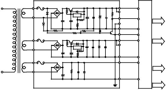
1 June 1990
10.2 DC POWER DISTRIBUTION
DC Power Supply Board |
Main Board |
CN417 |
CN100 |
FU100 |
R100 |
Q100 |
|
|
|
|
|
|
CN101 |
|
CN107 |
|
|
|
-1 |
-5 |
ST100 |
|
|
|
|
|
|
-6 |
|
-6 |
[5]Vc |
|
|||
|
|
|
|
|
D102 |
|
|
|
|
|
|
|
|
|
||
|
|
D100 |
|
|
|
|
|
|
R103 |
CN103 |
( |
To |
|
|
||
|
|
|
|
|
|
|
|
|
|
) |
|
|||||
|
10VAC |
|
|
|
IC100 |
|
|
D103 |
-2 |
Sorter |
|
|||||
|
|
ON |
|
|
+ |
|
|
CN102 |
|
CN108 |
|
|
||||
|
|
|
|
|
|
|
|
|
|
|
-2 |
|
-1 |
Zero |
|
|
|
CN100 |
|
+ |
|
+ |
|
C103 |
C104 |
|
|
C112 |
|
|
|||
|
|
|
|
|
|
CN103 |
|
To |
Cross |
[24]VA |
||||||
|
|
|
|
|
R101 |
|
|
( |
||||||||
|
|
|
|
|
|
|
|
|
|
|
||||||
|
-6 |
D101 |
C100 |
|
C101 |
|
|
|
|
|
-1 |
Sorter |
) |
|
||
|
|
|
|
|
R102 |
|
|
|
|
|
CN101 |
|
CN107 |
|
|
|
|
|
R104 |
|
|
|
|
|
|
|
|
|
|
|
|||
|
|
|
|
|
|
|
|
|
|
|
-5 |
|
-5 |
[0]GND |
|
|
|
|
|
|
|
|
|
|
|
|
|
|
|
|
|||
|
|
|
|
|
R105 |
|
|
|
|
|
|
|
|
|
|
|
|
|
|
|
|
|
|
|
|
|
|
CN102 |
|
CN108 |
|
|
|
|
|
|
|
|
|
R106 |
|
C105 |
Q101 |
-1 |
|
-2 |
[0]GND |
|
||
|
CN100 |
FU101 |
|
|
|
|
CN101 |
|
CN107 |
|
||||||
115V |
R107 |
|
|
|
|
|
|
|
|
|
|
|
||||
-3 |
ST101 |
|
Q102 |
|
|
|
|
|
|
-4 |
|
-4 |
|
|
||
220/240V |
|
|
|
|
|
|
|
|
[24]VA |
[5]VC |
||||||
|
|
|
|
D104 |
|
|
|
|
|
|
|
|
||||
|
|
|
|
|
|
|
|
|
|
|
|
|
|
|
||
|
26VAC |
|
|
|
|
|
+ |
|
|
|
|
CN103 |
( |
To |
) |
|
|
|
|
|
|
IC101 |
|
C109 |
D105 |
|
C113 |
-3 |
Sorter |
|
|||
|
|
|
+ |
|
+ |
|
C108 |
|
|
|
|
|
|
|||
|
CN100 |
|
|
|
|
|
|
|
|
CN101 |
|
CN107 |
|
|
||
|
|
|
|
|
|
|
|
|
|
|
|
|
|
|||
|
-4 |
|
C110 |
C107 |
|
|
|
|
|
|
|
|
|
|||
|
|
|
|
|
|
|
|
-3 |
|
-3 |
|
|
||||
|
|
|
|
|
|
|
|
|
|
[0]GND |
|
|||||
|
CN100 |
FU102 |
|
|
|
|
|
|
|
|
|
CN101 |
|
CN107 |
|
|
|
|
|
|
|
|
|
|
|
|
|
|
|
||||
|
-1 |
ST102 |
|
|
|
|
|
|
|
|
|
-2 |
|
-2 |
[30]VM |
|
|
|
|
|
|
|
|
|
|
|
|
|
|
|
|
|
|
|
26VAC |
|
|
|
|
|
|
|
|
|
|
|
|
|
|
[30]VM |
|
|
|
|
|
|
|
|
|
|
|
|
|
|
|
|
|
|
CN100 |
+ |
|
|
|
|
|
CN417 |
C110 |
R108 |
C111 |
C114 |
CN101 |
CN107 |
|
|
-2 |
|
|
|
|
||
-3 |
|
|
|
|
-1 |
-1 |
|
|
|
|
|
|
|||
|
|
|
|
|
|
|
[0]GND |
[0]GND
1-26
SECTION 2
SECTIONAL DESCRIPTION

1 June 1990
1. DRUM
1.1 OPC DRUM CHARACTERISTICS
An OPC has the characteristics of:
1.Being able to accept a high negative electrical charge in the dark. (The electrical resistance of a photoconductor is high in the absence of light.)
2.Dissipating the electrical charge when exposed to light. (Exposure to light greatly increases the conductivity of a photoconductor.)
3.Dissipating an amount of charge in direct proportion to the intensity of the light. That is, where stronger light is directed to the photoconductor surface, a smaller voltage remains on the OPC.
4.Being less sensitive to changes in temperature (when compared to selenium F type drums). This makes it unnecessary to monitor and control the drum temperature.
2-1
Loading...