


 Loading...
RICOH FT4430
S E R V I C E M A N U A L
RICOH COMPANY, LTD.
SECTION 1
OVERALL MACHINE
INFORMATION

Table of Contents
SPECIFICATIONS . .
OPERATION PANEL
SECTION A . . . . . . . . .
SECTION B . . . . . . . . .

16 April ’88
SPECIFICATIONS
Configuration: |
|
|
Desk top |
|
|
|
|
|
|
Copying Process: |
Dry electrostatic transfer system |
||||||||
Original: |
|
|
Sheet/book |
|
|
|
|
||
Original Size: |
|
|
Maximum A3 (11“ x 17”) |
|
|
||||
Copy Paper Size: |
Maximum A3 (11“ x17”) |
|
|
||||||
|
|
|
Minimum A6 (51/2" x 81/2”) |
|
|
||||
Copy Paper Weight: |
Cassette feed |
52 to 128 g/m2 (14 lb to 34 lb) |
|||||||
|
|
|
Manual feed |
52 to 157 g/m2 (14 lb to 42 lb) |
|||||
Reproduction |
Ratios: |
See the following table: |
|
|
|||||
|
|
|
|
v |
|
|
|
|
|
|
|
|
|
A4 Version |
|
Letter Version |
|
||
|
|
|
|
1:1.41 |
|
|
1:1.55 |
|
|
|
|
Enlargement |
1:1.22 |
|
|
1:1.29 |
|
||
|
|
|
|
1:1.15 |
|
|
1:1.21 |
|
|
|
|
Full Size |
|
. |
|
|
|
:G |
|
|
|
|
1:1 |
|
|
|
11 |
|
|
|
|
|
|
● |
|
|
|
. |
|
|
|
|
|
1:0 .93 |
|
|
1:0 ● 93 |
|
|
|
|
|
|
. |
82 |
|
|
. |
|
|
|
|
|
1:0.● |
|
|
1:0. . 77 |
|
|
|
|
Reduction |
1:0.71 |
|
|
1:0.74 |
|
||
|
|
|
|
1:0.65 |
|
|
1:0.65 |
|
|
|
|
|
|
|
|
|
|||
Zoom: |
|
|
From 65% to 155% in 1 % steps |
||||||
Reproduction |
Ratio |
Full size - Enlargement or |
|
|
|||||
Change: |
|
|
Full size - Reduction in less than 5 seconds |
||||||
|
|
|
Enlargement - |
Reduction |
or |
||||
|
|
|
Reduction |
- Enlargement in less than 6.5 |
|||||
|
|
|
|
|
|
seconds |
|
|
|

16 April ’88
Copying Speed:
The copy speed (in copies per minute) is shown in the following tables:
A4 Version
A3 |
B4 |
A4 |
B5 |
A4R |
B5R |
11 |
13 |
20 |
20 |
15 |
15 |
|
|
|
|
|
|
Letter Version
LDG LG LT LT(R)
12 |
15 |
22 |
16 |
|
When used with document feeder, A4 (LT) speed |
|
is 17 cpm (sideways). |
First-Copy Time: |
6.0 seconds (A4 or 81/2” x 11”) |
Warm-Up Time: |
Approximately 100 seconds (23°C) |
Copy Number Input: |
Numeral keys, 1 to 999, (count up or count down) |
Special Functions: |
- Margin adjustment |
|
- Auto size magnification mode |
|
-2 single copies mode |
|
- Auto paper select and auto reduce/eniarge |
|
mode (with ADF only) |
Manual Image Density |
7 Steps (Development bias variable) |
Selection: |
|
Automatic Reset: |
1 min. standard setting; can also be set to 3 min. |
|
or no auto reset. |
|
All functions canceled except cassette selection. |
|
Quantity entered returns to “1”, and reproduction |
|
ratio returns to full size. |
1-2

|
|
|
16 April ’88 |
Paper Feed: |
|
- Double universal cassette feed, 250 sheets each |
|
|
|
|
(auto cassette shift) |
|
|
|
- Manual feed table |
|
|
|
- Optional large capacity tray (LCT) at second |
|
|
|
feed station. |
Paper-Feed System: |
Friction-pad system |
||
Exposure System: |
Slit exposure, moving optics |
||
Lens: |
|
|
Through lens, F8, f = 180mm |
Light Source: |
|
Halogen lamp (85 V, 290 W) |
|
Photoconductor: |
Selenium drum (F type) |
||
Charge System: |
Dual wire dc corona |
||
Erase: |
|
|
LED lamp unit (34 LEDs) |
Development |
System: |
Magnetic brush roller |
|
Toner |
Density |
Control: |
Automatic, direct density sensing |
Development Bias |
Automatic voltage change (The control board |
||
System: |
|
monitors the selected image density level, drum |
|
|
|
|
temperature, and rest time.) |
Toner |
Replenishment: |
Cartridge exchange (300 g/cartridge) |
|
Toner |
Consumption: |
Approx. 7,500 copies/cartridge (A47% original) |
|
Cleaning System: |
Blade and brush |
||
Quenching System: |
Photo-quenching |
||
Image Transfer: |
Single wire dc corona, pre-transfer lamp |
||
Paper Separation: |
Dual wire ac corona and pick-off pawls |
||
Image Fusing: |
Heat/pressure - roller type |
||
Fusing Lamp: |
|
Halogen lamp (840 W) |
|
1-3
16 April ’88 |
|
|
Electronic Control |
8-bit microprocessor |
|
System: |
|
|
Copy Tray Capacity: |
250 sheets (B4 / 10” x 14”) |
|
|
100 sheets (A3 / 11” x 17“) |
|
Self-diagnostics: |
19 codes, displayed in the copy counter |
|
Power Source: |
110V/60Hz....15A |
|
|
115V/60Hz....15A |
|
|
220V/50Hz....8A |
|
|
220V/60Hz....8A |
|
|
240V/50HZ....8A |
|
Power Consumption: |
Warm-up: |
1.0 kW |
|
Stand-by: |
0.08 kW |
|
Copying: |
0.42 kW (A4 sideways) |
|
Maximum: |
1.22 kW |
Dimensions: |
Copier only: |
734 x 654 x 390 mm |
( W x D x H ) |
|
28.9 x 25.8 x 15.4 inches |
|
Full System: |
1363 x 654 x 460 mm |
|
|
53.7 x 25.7 x 14.1 inches |
Weight: |
65 kg (143 lb) (Copier only) |
|
|
100 kg (221 lb) (Full System Without table) |
|
Optional Equipment: |
Document Feeder |
|
|
Sorter (20 bins) |
|
|
Large Capacity Tray |
|
|
Editor Board (requires editing eraser lamp) |
|
|
Color Development Unit (Red, Blue, Green) |
|
1-4
16 April ’88
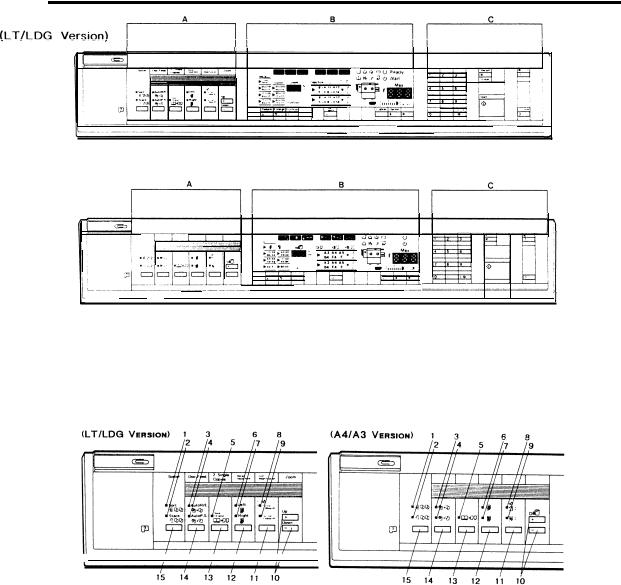
OPERATION PANEL
(A4/A3 Version)
SECTION A
1. Sort Indicator |
9. Copy Image Size Indicator |
||
2. |
Stack Indicator |
10. Zoom Keys |
|
3. |
Auto Reduce/Enlarge Indicator |
11. |
Size Magnification Key |
4. Auto Paper Select Indicator |
12. |
Margin Adjustment Key |
|
5.2 Single Copies Indicator |
13.2 Single Copies Key |
||
6. |
Left Margin Adjustment Indicator |
14. |
Auto Selection Key |
7. Right Margin Adjustment Indicator |
15. Sorter Key |
||
8. |
Original Image Size Indicator |
|
|
1-5

16 April ’88
SECTION B
1. (LT/LDG Version)
 (A4/A3 Version)
1,
24
3<
4 ●
5 .
6 ,
7 . |
|
Auto Image Density Key |
8 ● |
|
Manual Image Density Key |
9 |
|
Manual Image Density Indicator |
10 |
|
Color Toner Indicator |
|
|
Misfeed Location Display |
11 |
|
Select Cassette Key |
12 |
|
Paper Size Indicator |
13 , |
32 |
Full Size Key |
14, |
33 |
Full Size Indicator |
15. |
34 |
Magnification Ratio Indicator |
16 |
35 |
Enlarge Key |
17( |
36 |
Reduce Key |
18 .
16 April ’88
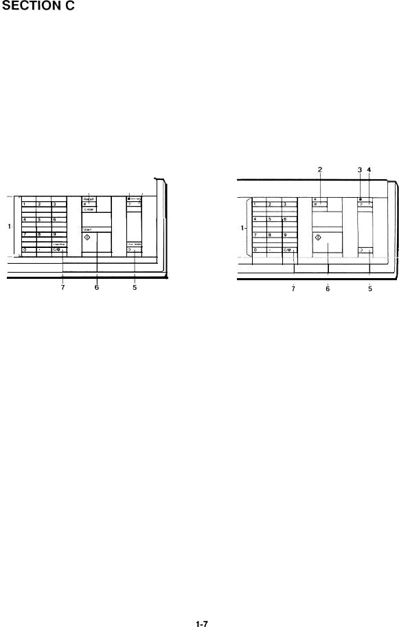
(LT/LDG Version) |
(A4/A3 Version) |
|
-
1.Number Keys
2.Recall/Enter Key
3.Interrupt Indicator
4.Interrupt Key
5.Clear Modes Key
6.Start Key
7.Clear/Stop Key
16 April ’88
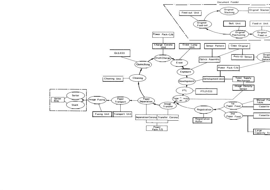
PAPER PATH
Paper feed starts from one of the two paper feed stations. The path followed depends on which cassette the operator has selected. For copy processing, all sheets follow the same path from the paper feed mechanism through the fusing unit. After that, copies are delivered to the receiving tray.
1. Paper Feed
A friction pad and feed roller mechanism separates one sheet of paper from the paper stack and feeds it to the registration rollers. The registration rollers are not turning at this time. The paper buckles slightly when the leading edge reaches the registration rollers. Buckling seats the sheet securely between the registration rollers and corrects skew.
1-10
16 April ’88
2. Registration
At the programmed time, the registration rollers start turning to feed the paper to the drum.
3. Image Transfer
The toner image on the drum surface is pulled from the drum onto the passing paper by the transfer corona.
4. Paper Separation
The separation corona breaks the electrostatic attraction between the paper and the drum. The suction of the vacuum fan pulls the paper onto the transport belt. The transport belt moves the paper with the developed copy image to the fusing unit.
5. Fusing
The paper passes between two rollers which bond the toner image to the paper by applying heat and pressure. At this point the copy is complete.
1-11
16 April ’88
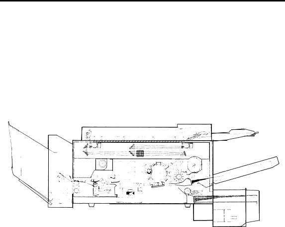
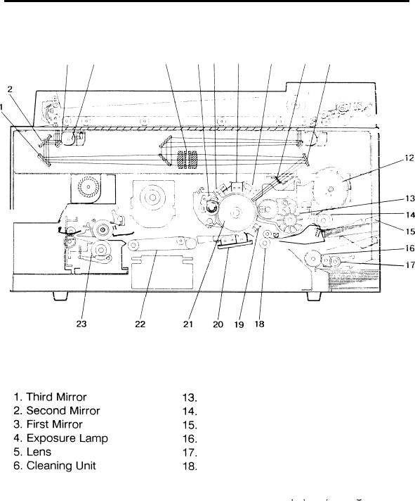
MECHANICAL COMPONENT LAYOUT
3 |
4 |
|
5 |
6 |
|
7 |
8 |
9 |
|
10 |
11 |
|
|||||||
|
|
|
|
|
|
|
|
|
|
|
|
|
|
|
|
|
|
|
|
|
|
|
|
|
|
|
|
|
|
|
|
|
|
|
|
|
|
|
|
|
|
|
|
|
|
|
|
|
|
|
|
|
|
|
|
|
|
|
|
|
|
|
|
|
|
|
|
|
|
|
|
|
|
|
|
|
|
|
|
|
|
|
|
|
|
|
|
|
|
|
|
|
|
|
|
|
|
|
|
|
|
|
|
|
|
|
|
|
|
|
|
|
|
|
|
|
|
|
|
|
|
|
|
|
|
|
|
|
|
|
|
|
|
|
|
|
|
|
|
|
|
|
|
|
|
|
|
|
|
|
|
|
|
|
|
|
|
|
|
|
|
|
|
|
|
|
|
|
|
|
|
|
|
|
|
|
|
|
|
|
|
|
|
|
|
|
|
|
|
|
|
|
|
|
|
|
|
|
|
|
|
|
|
|
|
|
|
|
|
|
|
|
|
|
|
|
|
|
|
7 . Quenching Lamp
8Main Corona Unit
9Erase Lamp Unit
10( Toner Shield Glass
11 Fourth Mirror
12 Toner Cartridge
Development Unit
First Feed Roller
First Cassette
Second Feed Roller
Pick-up Roller (LCT)
Registration Roller
19 . Pre-Transfer Lamp (PTL) /lmaqe Density Sensor Board
20.Transfer/Separation Corona Unit
21.Selenium Drum
22.Transport Belt
,23. Fusing Unit
1-12
16 April ’88
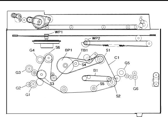
DRIVE LAYOUT
Gears |
Wire Pulleys |
|
G1 |
Second Feed Clutch Gear |
WP1 Scanner Drive Pulley |
G2 |
Pick-up Roller Drive Gear(LCT) |
WP2 Second Scanner Drive Pulley |
G3 |
First Feed Clutch Gear |
|
G4 |
Toner Supply Clutch Gear |
Timing Belt |
G5 |
Hot Roller Drive Gear |
|
G6 |
Exit Roller Drive Gear |
TB1 Drum Drive Belt |
Sprockets |
Belt |
|
S1 |
Main Motor Sprocket |
B1 Transport Belt |
S2 |
Fusing Drive Sprocket |
Belt Pulley |
S3 |
Feed Drive Sprocket |
|
S4 |
Cleaning Drive Sprocket |
BP1 Drum Drive Pulley |
S5 |
Toner Collection Bottle |
|
|
Drive Sprocket |
|
S6 |
Development Drive Sprocket |
Chains |
Cl Main Drive Chain
1-13
16 April ’88 |
. |
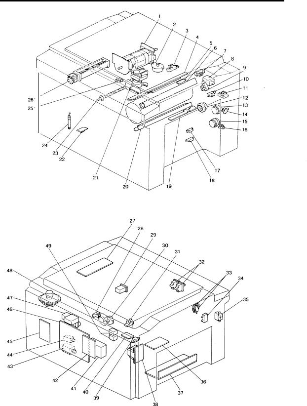
ELECTRICAL COMPONENT LAYOUT
1-14
|
|
|
. |
16 April ’88 |
|
|
|
|
|
1. Main Motor - Ml |
27. Lamp Regulator PCB - PCB1 |
|||
2. Lens Drive Motor - M2 |
28. |
Second Scanner Home Position |
||
3. Lens HP Sensor - S1 |
|
Sensor - S12 |
|
|
4. Quenching Lamp - L1 |
29. |
Total Counter - CO1 |
|
|
5. Drum Heater |
30. Second Scanner Motor - M5 |
|||
6. Erase Lamp - L2 |
31. |
Scanner Home Position |
|
|
7. Pulse Generator Sensor - S2 |
|
Sensor - S13 |
|
|
8. Toner Supply Solenoid - SOL1 |
32. |
Front Cover Safety Switch - SW2 |
||
9. Color Toner End Sensor - S3 |
33. |
Door Switch - SW1 |
|
|
10. |
Manual Feed Sensor - S4 |
34. |
Main Motor Capacitor - C |
|
11. Color Toner Sensors - S5 |
35. |
Main Switch - SW3 |
|
|
12. |
Registration MC - MCI |
36. Relay PCB - PCB2 |
|
|
13. |
First Paper Feed MC - MC2 |
37. DC Power Supply Unit - PSU |
||
14. |
First Paper End Sensor - S6 |
38. Transformer - TR1 |
|
|
15. |
Second Paper Feed MC - MC3 |
39. Fusing Triac - FT |
|
|
16. |
Second Paper End Sensor - S7 |
40. Heater Control PCB - PCB5 |
||
17. |
First Paper Size Sensor - S8 |
41. Power Pack - T/S - P1 |
|
|
18. Second Paper Size Sensor - S9 |
42. Interface Board - PCB3 |
|
||
19. Registration Sensor - S10 |
43. Cleaning Solenoid - SOL2 |
|||
20. |
Pre Transfer Lamp - L3 |
44. Pick-off Solenoid - SOL3 |
|
|
21. Vacuum Fan Motor - M3 |
45. Feed Control PCB - PCB4 |
|||
22. |
Toner Overflow Sensor - S14 |
46. Main PCB - PCB6 |
|
|
23. |
Fusing Lamp - L4 |
47. Power Pack - C/B - P2 |
|
|
24. |
Oil End Sensor - S15 |
48. Scanner Drive Motor - M6 |
||
25. |
Paper Exit Sensor - S11 |
49. AC Drive Relay - R1 |
|
|
26. Exhaust Blower Motor - M4
1-15

16 April ’88
ELECTRICAL COMPONENT DESCRIPTIONS
SYMBOL |
NAME |
Motors |
|
Ml |
Main Motor |
M2 |
Lens Drive Motor |
M3 |
Vacuum Fan Motor |
M4 |
Exhaust Blower |
|
Motor |
M5 |
Second Scanner |
|
Motor |
M6 |
Scanner Drive Motor |
Magnetic |
Clutches |
MC1 |
Registration MC |
MC2 |
First Paper Feed MC |
MC3 |
Second Paper Feed |
|
MC |
FUNCTION |
LOCATION |
Drives all main unit components |
1 |
except otics unit and fans/bIowers. |
|
(100Vac) |
|
Positions the lens. (dc stepper) |
2 |
Provides suction so that paper is |
21 |
held firmly on the transport belt. (100 |
|
Vat) |
|
Removes heat from around the |
26 |
fusing unit. (100 Vat) |
|
Positions the second scanner. (dc |
30 |
stepper) |
|
Drives the scanner. (dc stepper) |
48 |
Drives the registration rollers. |
12 |
Starts paper feed from the first paper |
13 |
feed station. |
|
Starts Paper feed from the second |
15 |
paper feed1’ station. |
|
Solenoids
SOL1 |
Toner Supply |
Energizes to supply toner. |
8 |
|
Solenoid |
|
|
SOL2 |
Cleaning Solenoid |
Moves the cleaning blade against the |
43 |
|
|
drum. |
|
SOL3 |
Pick-off Solenoid |
Brings the pick-off pawls into contact |
44 |
|
|
with the drum. |
|
Switches
SW1 |
Door Switch |
SW2 |
Front Cover Safety |
|
Switch |
SW3 |
Main Switch |
Sensors
S1 |
Lens Home Position |
|
Sensor |
S2 |
Pulse Generator |
Enables the Door Open indicator. |
33 |
Cuts ac power to ac components. |
32 |
Supplies power to the copier. |
35 |
Informs the CPU when the lens is at |
3 |
the full size position. |
|
Supplies timing pulses to the main |
7 |
board. |
|
1-16

SYMBOL |
NAME |
S3 |
Color Toner End |
|
Sensor |
S4 |
Manual Feed Sensor |
S5 |
Color Toner Sensors |
S6 |
First Paper End |
|
Sensor |
S7 |
Second Paper End |
|
Sensor |
S8 |
First Paper Size |
|
Sensor |
S9 |
Second Paper Size |
|
Sensor |
S10 |
Registration Sensor |
S11 |
Paper Exit Sensor |
S12 |
Second Scanner |
|
Home Position |
|
Sensor |
S13 |
Scanner Home |
|
Position Sensor |
S14 |
Toner Overflow |
|
Sensor |
S15 |
Oil End Sensor |
Printed Circuit Boards |
|
PCB1 |
Lamp Regulator PCB |
PCB2 |
Relay PCB |
PCB3 |
Interface PCB |
PCB4 |
Feed Control PCB |
PCB5 |
Heater Control PCB |
PCB6 |
Main PCB |
Lamps |
|
L1 |
Quenching Lamp |
L2 |
Erase Lamp |
L3 |
Pre-Transfer Lamp |
|
16 April ’88 |
FUNCTION |
LOCATION |
Detects when it is time to add toner. |
9 |
Detects when the manual feed table |
10 |
is open. |
|
Detects which color toner |
11 |
development unit is installed. |
|
Informs the CPU when the first |
14 |
cassette runs out of paper. |
|
Informs the CPU when the second |
16 |
cassette runs out of paper. |
|
Determines what size paper is in the |
17 |
first cassette. |
|
Determines what size paper is in the |
18 |
second cassette. |
|
Misfeed detector and ON/OFF timing. |
19 |
Misfeed detector. |
25 |
Informs the CPU when the second |
28 |
scanner is at the home position. |
|
Informs the CPU when the scanner is |
31 |
at the home position. |
|
Detects when the used toner bottle is |
22 |
full . |
|
Detects low oil condition. |
24 |
Regulates the exposure lamp voltage. |
27 |
Main power relay. Provides 100 volts |
36 |
ac to motors and circuits. |
|
Interfaces the data between the |
42 |
copier main board and the sorter |
|
and/or DF main boards. |
|
Contains multiplexing circuitry to |
45 |
control feed components. |
|
Controls heater switching. |
40 |
Controls all copier functions both |
46 |
directly and through other PCBS. |
|
Neutralizes any charge remaining on |
4 |
the drum surface after cleaning. |
|
Discharges the drum outside of the |
6 |
image area. Provides lead/traiI edge |
|
erase and editing functions. |
|
Reduces charge on the drum surface |
20 |
before transfer. |
|
1-17
16 April ’88
SYMBOL |
NAME |
L4 |
Fusing Lamp |
Power Packs |
|
P1 |
Power Pack - T/S |
P2 |
Power Pack - C/B |
FUNCTION |
LOCATION |
Provides heat to the fusing unit. |
23 |
Provides dc voltage for the transfer |
41 |
and provides ac and dc voltage for |
|
separation coronas. |
|
Provides high voltage power for the |
47 |
charge corona and the development |
|
roller bias. |
|
Transformer
TR1 Transformer
Counter
CO1 Total Counter
Steps down the wall voltage to 100 |
38 |
Vat. |
|
Keeps track of the total number of |
29 |
copies made. |
|
Relays
R1 AC Drive Relay
Others
c |
Main Motor Capacitor |
FT |
Fusing Triac |
PSU |
DC Power Supply |
|
Unit |
Main Power Relay |
49 |
Start capacitor |
34 |
Switches fusing lamp on and off. |
39 |
Rectifies 100 Vac input and outputs |
37 |
dc voltages. |
|
1-18
16 April ’88
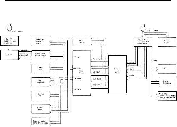
AC AND DC POWER DISTRIBUTION
The ac power supply is filtered then distributed to the fusing lamp and the main transformer. The transformer supplies 100 volts to the cooling fan, vacuum fan, and the main motor.
The”dc power supply unit receives ac 26, 16, and 10 volts, via fuses, from the main transformer. These voltages are rectified and regulated to 24, 15 and 12, and 5 volts respectively and distributed to the sorter, ADF, and the copier main board. All supplies have their own ground line.
The main board supplies voltage to all copier electrical components including: power packs, PCBs, and relays. It also supplies the editor.
The LCT has a separate power supply.
1-19
16 April ’88
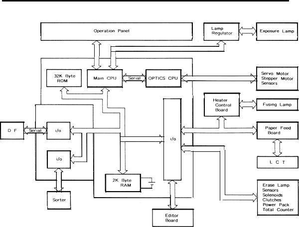
OVERALL MACHINE CONTROL
The base copier has two CPUs on the main board that control all machine operations (the main CPU and the optics CPU).
The main CPU is the main controller of this copier. It monitors the input signals from sensors and controls the electrical devices through program mable 1/0 devices. The main board has a RAM (2 kilobytes) for the service program function. A battery backs up the power to this RAM. This CPU con trols the fusing lamp, via the heater control board, the exposure lamp, via the lamp regulator, and motors directly from the main board.
The optics CPU controls the servomotor (15 volts) and the stepper motors (24 volts) for the optics section.
The interface board is connected to the copier main board when the document feeder and/or sorter are installed.
1-20
16 April ’88
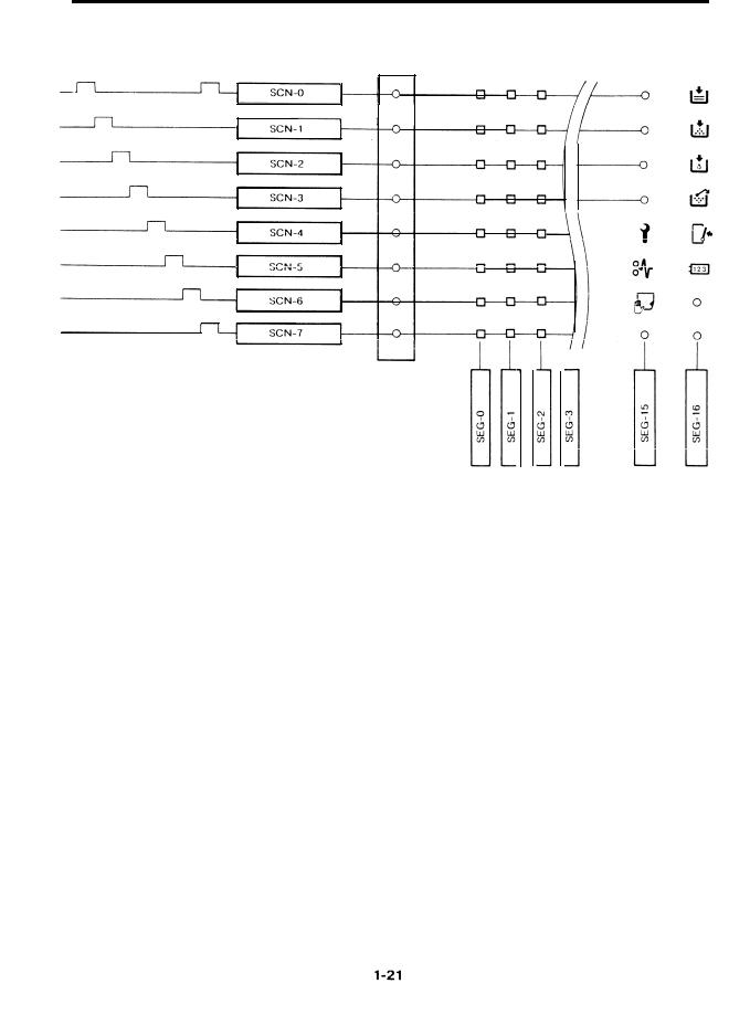
OPERATION PANEL CONTROL
The CPU controls all functions of the operation panel. The CPU sends data to programmable 1/0 devices which form a multiplexing circuit consisting of 8 scan lines and 17 segment lines, Transistors drive all the scan lines at 12 volts to reduce effects from noise.
The multiplexing circuit lights all displays and monitors all keys of the operation panel. The door switch is also monitored by this circuit and acts like any other operation panel key. The counters are also controlled by the operation panel multiplexing circuit and act like the operation panel lamps.
SECTION 2
DETAILED SECTION DESCRIPTIONS

OVERVIEW . . . . . . . . . . . . . . . . . . . . . . . . . . . . . . . . . . . . . . . . . . . . . . . . . : . . . . . . ...2-6 LEAD EDGE ERASE . . . . . . . . . . . . . . . . . . . . . . . . . . . . . . . . . . . . . . . . . . . . . . . . . ...2-7 SIDE ERASE . . . . . . . . . . . . . . . . . . . . . . . . . . . . . . . . . . . . . . . . . . . . . . . . . . . . . . . ...2-7 I. Side Erase Operation . . . . . . . . . . . . . . . . . . . . . . . . . . . . . . . . . . . . . . . . . . ...2-8 TRAIL EDGE ERASE . . . . . . . . . . . . . . . . . . . . . . . . . . . . . . . . . . . . . . . . . . . . . . . . . ...2-9 ERASE LAMP CIRCUIT . . . . . . . . . . . . . . . . . . . . . . . . . . . . . . . . . . . . . . . . . . . . . . ...2-10
OPTICS . . . . . . . . . . . . . . . . . . . . . . . . . . . . . . .. . . . . . . . . . . . . . ...2-12
OVERVIEW . . . . . . . . . . . . . . . . . . . . . . . . . . . . . . . . . . . . . . . . . . . . . . . . . . . . . . . ...2-12 SCANNER DRIVE . . . . . . . . . . . . . . . . . . . . . . . . . . . . . . . . . . . . . . . . . . . . . . . . . . ...2-13 I. Scanner Drive Mechanism . . . . . . . . . . . . . . . . . . . . . . . . . . . . . . . . . . . . . . ...2-13
2.Scanner Motor Control LENS/MIRRORPOSITIONING I. Lens Drive . . . . . . . . . . .
Z. Lens Positioning . . . . . .
3.Second Scanner Drive .
4. Second Scanner Positioning . . . . . . . . . . . . . . . . . . . . . . . . . . . . . . . . . . . . ...2-18 STEPPER MOTOR CONTROL . . . . . . . . . . . . . . . . . . . . . . . . . . . . . . . . . . . . . . . . ...2-19 AUTOMATIC IMAGE DENSITY SENSING . . . . . . . . . . . . . . . . . . . . . . . . . . . . . . . ...2-20 EXPOSURE LAMP CONTROL . . . . . . . . . . . . . . . . . . . . . . . . . . . . . . . . . . . . . . . . ...2-21 Service Call Conditi.ons . . . . . . . . . . . . . . . . . . . . . . . . . . . . . . . . . . . . . . . . . . . . . . ...2-22
DEVELOPMENT . . . . . . . . . . . . . . . . . . . . . . . . . . . . . . . . . . . . . . ...2-23 overview . . . . . . . . . . . . . . . . . . . . . . . . . . . . . . . . . . . . . . . . . . . . . . . . . . . . . . . . . ...2-23 DRIVE MECHANISM . . . . . . . . . . . . . . . . . . . . . . . . . . . . . . . . . . . . . . . . . . . . . . . . ...2-24 SEALS AND END MAGNETS . . . . . . . . . . . . . . . . . . . . . . . . . . . . . . . . . . . . . . . . . ...2-25 CROSS-MIXING . . . . . . . . . . . . . . . . . . . . . . . . . . . . . . . . . . . . . . . . . . . . . . . . . . . ...2-26 IMAGE DENSITY CONTROL . . . . . . . . . . . . . . . . . . . . . . . . . . . . . . . . . . . . . . . . . ...2-27
1. ManualImag eDensityControl . . . . . . . . . . . . . . . . . . . . . . . . . . . . . . . . . . . ...2-27
Z. Automatic Image Density Control . . . . . . . . . . . . . . . . . . . . . . . . . . . . . . . . ...2-28
3. Bias Compensation Factors . . . . . . . . . . . . . . . . . . . . . . . . . . . . . . . . . . . . . ...2-29
4. Rest Time Compensation (V2) . . . . . . . . . . . . . . . . . . . . . . . . . . . . . . . . . . . ...2-29
5. Drum Temperature Compensation (V3) . . . . . . . . . . . . . . . . . . . . . . . . . . . . . .2-30
6. Total Bias (VT) . . . . . . . . . . . . . . . . . . . . . . . . . . . . . . . . . . . . . . . . . . . . . . . . ...2-30
BIAS FOR ID SENSING . . . . . . . . . . o . . . . . . . . . . . . . . . . . . . . . . . . . . . . . . . . . . . ...2-31 BIAS CONTROL CIRCUIT . . . . . . . . . . . . . . . . . . . . . . . . . . . . . . . . . . . . . . . . . . . . ...2-32
COLOR DEVELOPMENT . . . . . . . . . . . . . . . . . . . . . . . . . . . . . . . . . . . . . . . . . . . . . . .2-33 I. Overview . . . . . . . . . . . . . . . . . . . . . . . . . . . . . . . . . . . . . . . . . . . . . . . . . . . . ...2-33 Z. Bias Control . . . . . . . . . . . . . . . . . . . . . . . . . . . . . . . . . . . . . . . . . . . . . . . . . ...2-33 3. Base Bias for Color . . . . . . . . . . . . . . . . . . . . . . . . . . . . . . . . . . . . . . . . . . . . ...2-33 4. Bias for lD Sensing . . . . . . . . . . . . . . . . . . . . . . . . . . . . . . . . . . . . . . . . . . . . ...2-33 5. Color Detection . . . . . . . . . . . . . . . . . . . . . . . . . . . . . . . . . . . . . . . . . . . . . . . ...2-34
SERVICE CALL CONDITION . . . . . . . . . . . . . . . . . . . . . . . . . . . . . . . . . . . . . . . . . ...2-35
TONER DENSITY DETECTION AND TONER SUPPLY . . . . . . . . ...2-36
TONER DENSITY DETECTION . . . . . . . . . . . . . . . . . . . . . . . . . . . . . . . . . . . . . . . ...2-36 TONER DENSITY CONTROL . . . . . . . . . . . . . . . . . . . . . . . . . . . . . . . . . . . . . . . . . ...2-37 TONER SUPPLY . . . . . . . . . . . . . . . . . . . . . . . . . . . . . . . . . . . . . . . . . . . . . . . . . . . ...2-39 I. Roller Drive Mechanism.. . . . . . . . . . . . . . . . . . . . . . . . . . , . . . . . . . . . . . . ...2-39 Z. Toner Agitator Drive Mechanism . . . . . . . . . . . . . . . . . . . . . . . . . . . . . . . . . ...2-40
TONER SUPPLY AMOUNT . . . . . . . . . . . . . . . . . . . . . . . . . . . . . . . . . . . . . . . . . . . ...2-41 l. Detect Supply Mode . . . . . . . . . . . . . . . . . . . . . . . . . . . . . . . . . . . . . . . . . . . ...2-41 Z. Fixed Supply Mode . . . . . . . . . . . . . . . . . . . . . . . . . . . . . . . . . . . . . . . . . . . . ...2-41
TONER END DETECTION . . . . . . . . . . . . . . . . . . . . . . . . . . . . . . . . . . . . . . . . . . . ...2-42 COLORTONERDENSITY DETECTIONANDCOLOR TONER SUPPLY . . . . . . . ...2-42 l. Color Toner Density Control . . . . . . . . . . . . . . . . . . . . . . . . . . . . . . . . . . . . ...2-42 Z. Color Toner End Detection. . . . . . . . . . . . . . . . . . . . . . . . . . . . . . . . . . . . . . ...2-43 3. Abnormal Condition . . . . . . . . . . . . . . . . . . . . . . . . . . . . . . . . . . . . . . . . . . . ...2-44
SERVICE CALL CONDITION . . . . . . . . . . . . . . . . . . . . . . . . . . . . . . . . . . . . . . . . . ...2-44
IMAGE TRANSFER AND PAPER SEPARATION . . . . . . . . . . . . . ...2-45
PRE-TRANSFER LAMP (PAL).... . . . . . . . . . . . . . . . . . . . . . . . . . . . . . . . |
. . . . . . ...2-45 |
IMAGE TRANSFER . . . . . . . . . . . . . . . . . . . . . . . . . . . . . . . . . . . . . . . . . . . |
. . . . . . ...2-45 |
PAPER SEPARATION . . . . . . . . . . . . . . . . . . . . . . . . . . . . . . . . . . . . . . . . . |
, . . . . . ...2-46 |
PRE-TRANSFER LAMP CIRCUIT. . . . . . . . . . . . . . . . . . . . . . . . . . . . . . . . . |
. . . . . ...2-47 |
TRANSFER/SEPARATIONCORONA CIRCUIT . . . . . . . . . . . . . . . . . . . . . . |
. . . . . ...2-48 |
PICK-OFF MECHANISM . . . . . . . . . . . . . . . . . . . . . . . . . . . . . . . . . . . . . . . . |
. . . . . ...2-49 |
l. Touch and Release Mechanism . . . . . . . . . . . . . . . . . . . . . . . . . . . . . |
. . . . . ...2-49 |
2. Side to Side Movement . . . . . . . . . . . . . . . . . . . . . . . . . . . . . . . . . . . |
. . . . . ...2-50 |
PICK-OFF CIRCUIT . . . . . . . . . . . . . . . . . . . . . . . . . . . . . . . . . . . . . . . . . . . . |
. . . . . ...2-51 |
DRUM CLEANING . . . . . . . . . . . . . . . . . . . . . . . . . . . . . . . . . . . . . ...2-52
OVERVIEW . . . . . . . . . . . . . . . . . . . . . . . . . . . . . . . . . . . . . . . . . . . . . . . . . . . . . . . ...2-52

. |
16 April ’88 |
DRUM
SELENIUM DRUM
Selenium has the characteristics of:
1 . Being able to accept a high positive electrical charge in the dark. (The electrical resistance of selenium is high in the absence of light.)
2 . Dissipating the electrical charge when exposed to light. (The conductivity of selenium is greatly enhanced by exposure to light.)
3 . Dissipating an amount of charge in direct proportion to the intensity of the light. That is, where a stronger light illuminates the selenium surface, a smaller voltage remains on the selenium.
The sensitivity of selenium changes slightly with variations in the surface temperature of the drum. (Under cool conditions, the drum may be excessively charged; this will result in background or excessive image density.) To prevent this, the CPU monitors the temperature variations around the drum and changes the development bias accordingly. Also, during cold periods, the drum heater warms the drum.
Drum sensitivity also depends on how long the drum has rested between copy runs. The copier’s CPU compensates for changes in drum sensitivity due to rest time by changing the development bias. This prevents variations in image density at the beginning of copy runs
The selenium drum used in this model has high sensitivity, good color reproduction, and good reproduction of low contrast originals (pencil originals, etc.)
2-1

16 April ’88
HANDLING THE DRUM
1 . Never touch the drum surface with bare hands.
2 ● Store the drum in a CooI dry place away from heat.
3 . When cleaning the drum, always wear gloves.
4 . Prime the drum with setting powder only when installing a new drum.
5 ● Never expose the drum to light for long periods.
6 . Drum conditioning is necessary after installing a new drum. In addition, it should be done at the following times:
1 ) When image density is reduced due to over exposure of the drum
2)After cleaning the drum
3)When the drum is lightly scratched.
7 ● Always keep the drum in the protective sleeve when inserting or pulling the drum out of the copier.
8 . Before inserting or pulling out the drum, pull the cleaning unit out slightly to avoid scratching the drum on the pick-off pawls.
9 . Return used drums to the distributor according to standard procedure.
16 April ’88
DRUM CHARGE
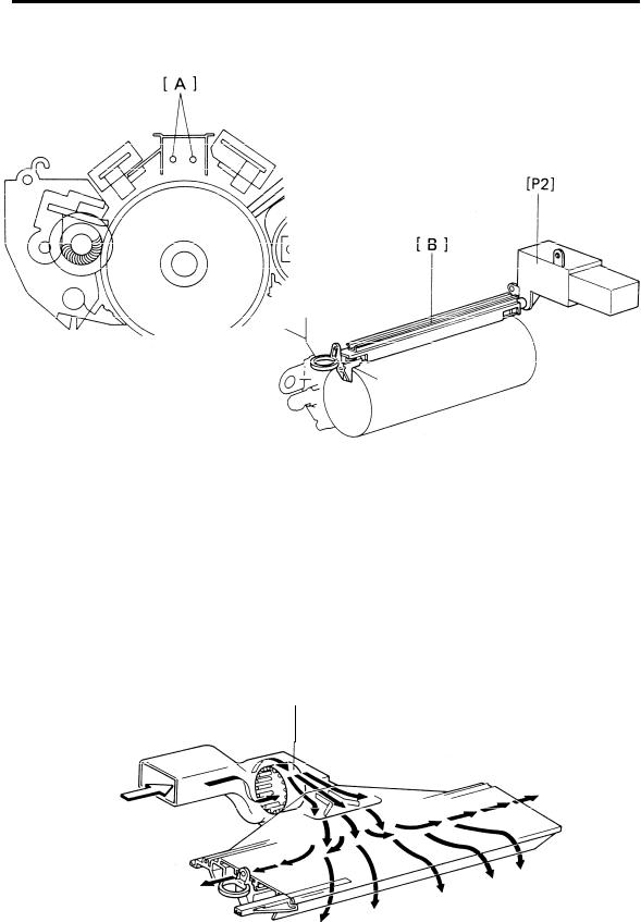
OVERVIEW
This copier uses a dual wire corotron [A] and a highly sensitive selenium drum. The corona wires generate a corona of positive ions when the charge power pack [P2] applies a high positive voltage. The selenium coating receives a uniform positive charge (750 t 50 volts) as it rotates past the corona unit [B].
The main motor fan [C] provides a smooth flow of air to the interior of the charge corona unit to prevent uneven build-up of positive ions. (An uneven build up of positive ions could cause uneven image density.)
[ c l
2-3
Loading...