


FT 4030

RICOH
RICOH
FIELD:
PEMOHT
D6CnYXHBRHIE
9
88
oolnc~oA
TEKHHKH
H
FT4060/FP4030
SERVICE
RICOH
COMPANY,
MANUAL
ITD.
1
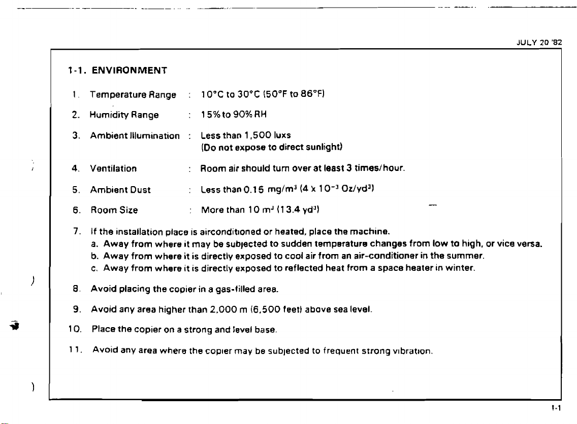
1-1.
ENVIRONMENT
1.
Temperature Range
2.
Humidity Range
3.
Ambient Illumination : Less than 1.500 Iuxs
4.
Ventilation
5. Ambient Dust
6.
RoomSize
7.
If
the
installation place
a.
Away
from where it may be subjected to sudden temperature changes from low
b.
Away from where
c.
Away from where
8.
Avoid placing the copier
9.
Avoid any area higher than 2,000
10. Place the copier on a strong and level
:
10°C to
:
15%to90%RH
(Do not expose to direct sunlight)
:
Room air should
:
Less than
:
More
is
aircondit~oned or heated, place the machine.
it
is directly exposed to cool air from
it
is directly exposed to reflected heat from a space heater in winter.
in
a
30°C
(50°F
0.1
5
mg/m"4
than
10
mJ
gas-filled area.
m
(6,500
base.
to
86°F)
turn
over at least 3 times/hour.
k
1
0-3
Oz/ydJl
(1
3.4
yd4)
an
air-conditioner
feet) above sea level.
-
to
in
the summer.
high.
or
vice
JULY
versa.
20
'82
I
I
I
I
I
1
1.
Avoid any area where the copter may be subjected to frequent strong v~bratron.
Car~entrr's Level

L
'E-
WnWINIW
33VdS
SlN3M13HlfID3U
I
C'I
i
JULY
20
'82
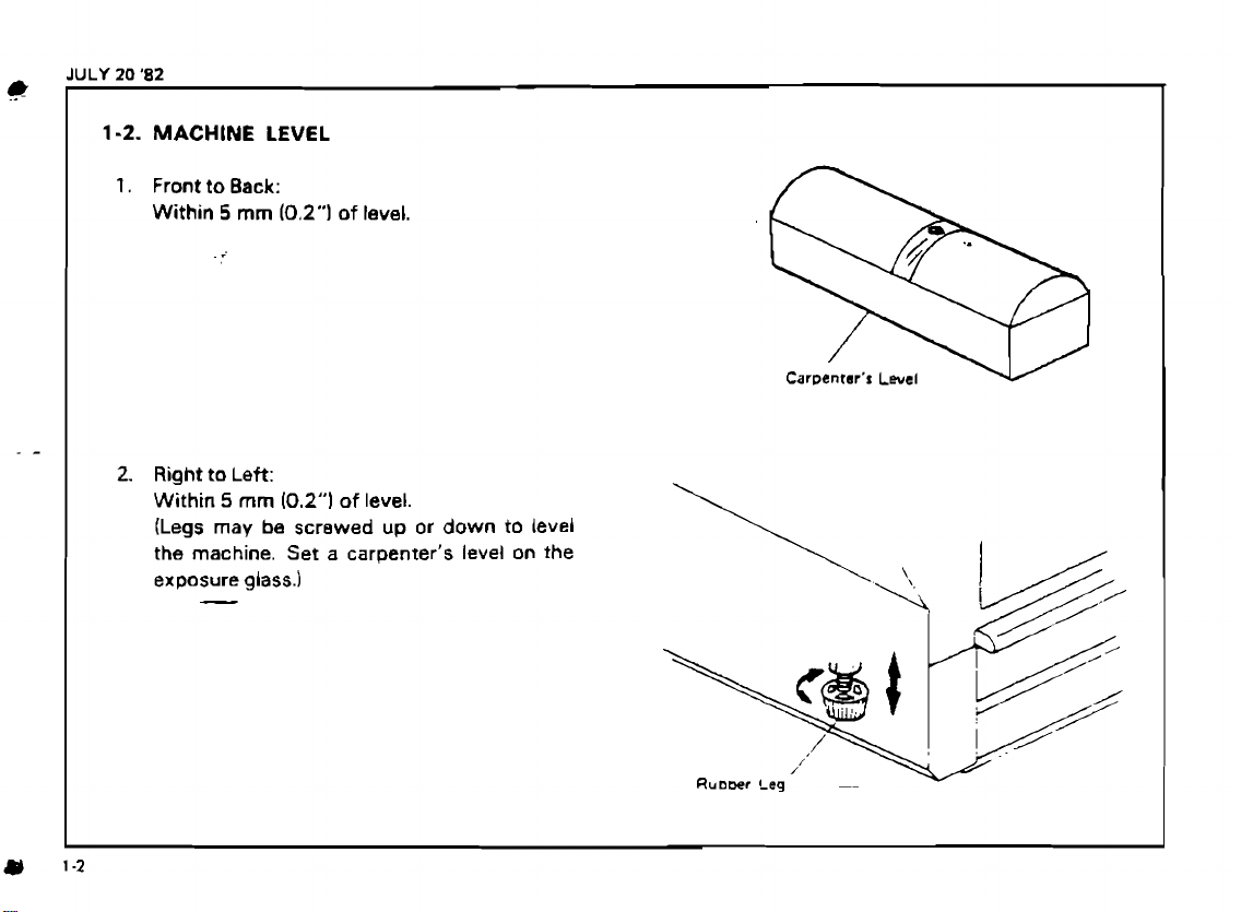
1-4.
1.
POWER
Input
1
15V/60Hz
SOURCE
Voltage
Level
:
More
than 12A
220V/50Hz : More than
240V/50Hz : More than
1
lP%~,..c,
,,I
I./\,L,.-
<
2. Permissible Voltage Fluctuation: = 10
3.
Permissible
--'At
least
rn
(1
6.4")
Extension
300V,
long.
30A
Cord:
capacity
7A
6A
and less
%
than
-
5
NOTE:
1.
8e
sure
to
ground the machine.
not connect the grounding wire
gas
pipe.)
2.
Make
sure
the
plug
is
firmly
the outlet.
3.
Avo~d
multi-w~ring.
4.
Do not set
anyrh~ng
on
the
power cord.
(Da
to
inserted
a
in

,
-
.
-..
,
.-.A,
2~~~?,~.i*A~.
UNPACKI IN^^^.^^;;;^,^:
.,
-r
-.- . -
....
Unpacking
_
,.
-
,
Accessory
-
..
.
-.
.a.
.
8
,
Procedure,LL;:,.
.-+
,
3*,.,,$@;2;i*::
,
,,
.
~l&k.
-
.;?2<?$':
.
-
+
,.;.
.
,A,
-9.-
,
.:-..
.
-a-
2.''
2-!.
_
-.
2-2.
.-
.
:,
...:...
.:&.
'.A*
..<,
.
%'.
c.,
.,-
.-.:
.
:
-
'4
A:,
,.
A,.;
-1;
I
I.
,
?;:,
.,-;,
-:
.
::;!
.......
.--.-... : ........-... L .......
Is;,'
L.
'
.,
.
-
:
,
-,:
:,-
.-,
"
*::I
..-
c.r,+-,
-
a
A?.
,-
--.
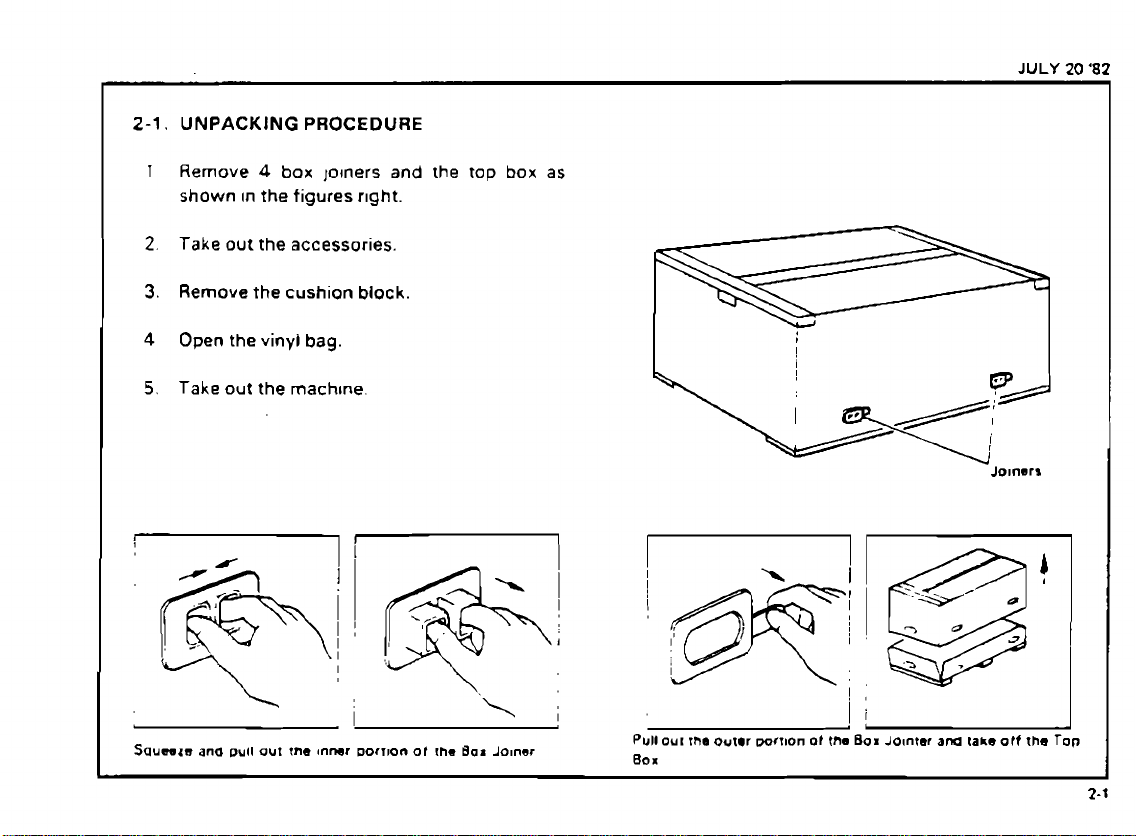
2-1.
UNPACKING
1
Remove
shown
2.
Take
3.
Remove
4
Open the vinyl
5.
Take
PROCEDURE
4
box
lolners
In
the
figures
r~ght.
out the accessories.
the
cushion
block.
bag.
out
the
machtne.
and
the
tap
box
as
JULY
20
'82
I
!
I
I
Jo~nerr
I
?
0
*
Squwzn
ana
pull
out
tne
Inner
I
Dorrron
ot
!he
Bar
Joiner
Pull OUI
80
x
I
the
outer
wrnon
of
the Box
Jointer
am
fake
otf
the
Top
SEP
30
'82
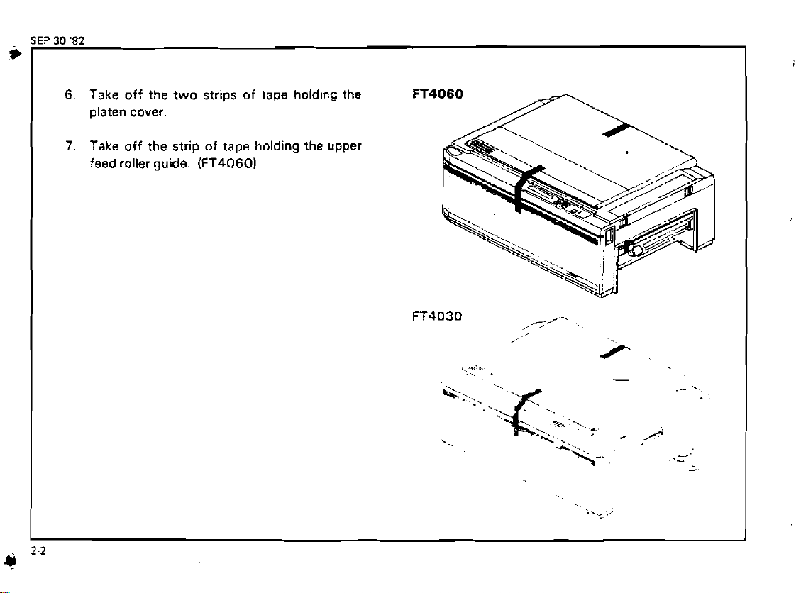
6.
Take off the two strips of tape holding the
platen cover.
7.
Take
off the strip of tape holding the upper
feed roller guide.
(FT40601
FT4060
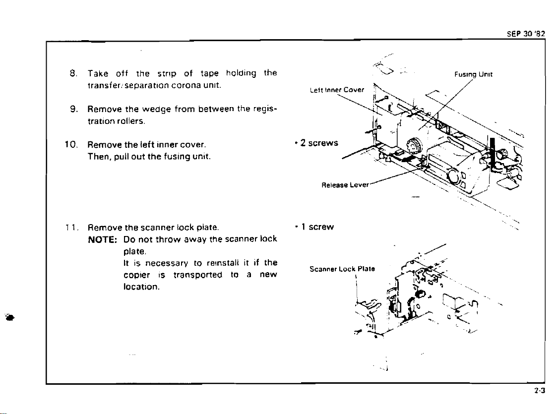
Take off the strlp of tape
transfer:separatlon corona unlt.
Remove the wedge from between the reglstratlon rollers.
Remove the left inner cover.
Then. pull out the fusing unit.
1
1.
Remove the scanner lock plate
NOTE:
Do
not throw away the scanner lock
date.
It is necessary to re~nstall it if the
copier
location.
is
transported to a new
holding
the
-
1
screw
Scanner Lock
Release
Lever
Plats
.I
-
-L/
'..
-.
SEP
30
82
i+
1
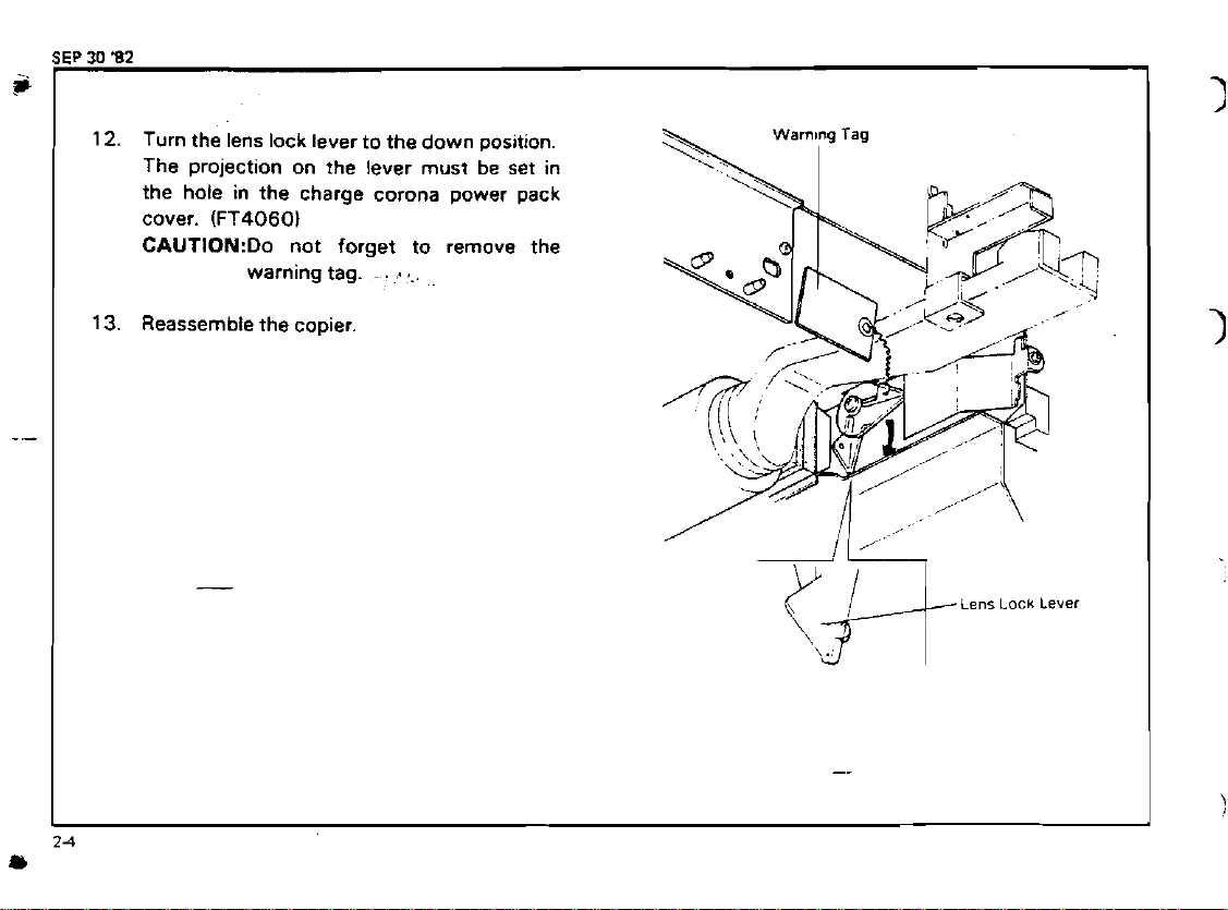
12.
Turn the ,ens lock lever to the down position.
The projection on the lever must be set in
the hole in the charge corona power pack
cover.
CAUTI0N:Do not forget to remove the
13.
Reassemble the copier.
(FT4060l
warning tag.
.
.
...
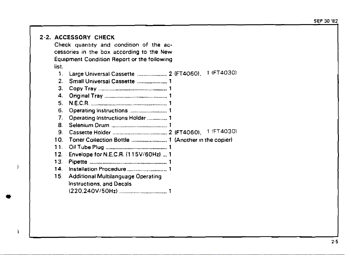
2-2.
ACCESSORY CHECK
Check
cessories in the box according to the New
Equ~prnent Condition Report or the following
list.
10. Toner Collection Bottle
1
1
15. Additional Multilanguage Operating
quantlty and condition of the ac-
1. Large Universal Cassette
2.
Small Universal Cassette
3.
Copy Tray
4.
Original Tray
5. N.E.C.R
6.
Operating Instructions
7.
Operating Instructions Holder
8.
Selenium Drum 1
9.
Cassette Holder
.................................................
..........................................
....................................................
........................................
.......................
.......................
..........................
...........................
1.
Oil Tube
2.
Envelope for N.E.C.R. (1 1 5Vl60Hz)
Instructions, and Decals
1220.240VI50Hz)
Plug
..........................................
....................................
...............
2
(FT40601. 1 (FT4030)
1
1
1
1
1
1
.
2
(FT4060). 1 fFT4030I
1 (Another in the copier)
1
...
1
1
.
.,
.
.
.
.
....
.'
,-.-I.
-
.
-.
<
.?,,
.
.
...
-
.
.
,.
.
*..
...
.......
-
?*.
'
..,.
tf-
v
.....
.
.-
-.
-.
..,*,,*:a*J.'.
..
%.
-.
._
.
...
..
..~
.*.
-.
I
I.'
:
*
.'
.,
.
.
........
..-.
JULY
20
'82
I
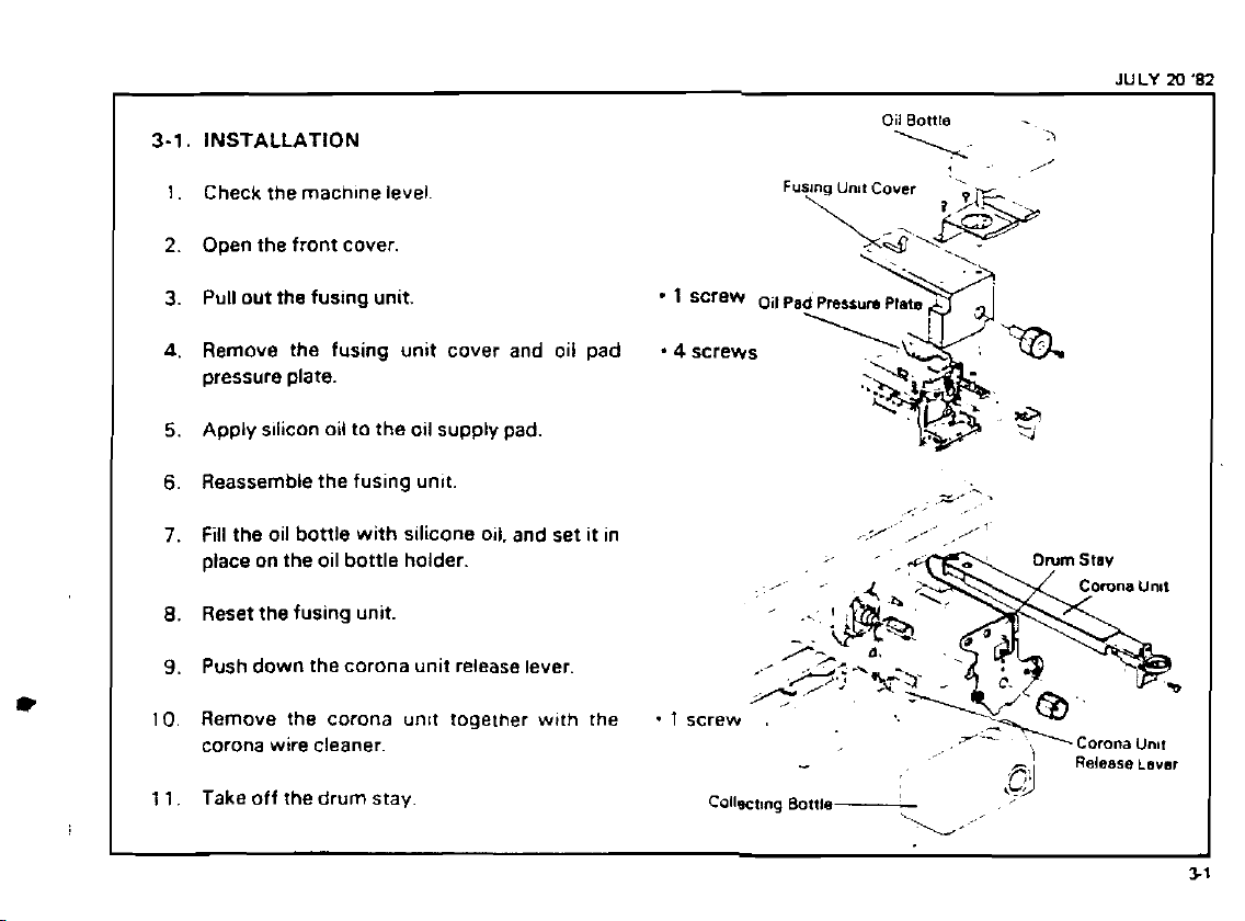
3-1.
INSTALLATION
1.
Check the machfne level
2.
O~en the front cover.
Pull out the fusing unit.
3.
A.
Remove the fusing unit cover and oil pad -4screws
pressure plate.
Apply sflicon oil to the oil supply pad.
5.
6.
Reassemble the fusing unft.
7.
Fill the oil bottle with silicone oil. and set it in
place on the oil bottle holder.
8.
Reset the fusing unit.
Push down the corona unit release lever.
9.
Oil Bottle
,
,..,
\.~
-
'>
.
'
/I
z-
'
.
,
,
/-1
,,
i
I
10.
Remove the corona unlt togelher w~th the
corona wire cleaner.
1 1.
Take off the drum stay.
.
1
screw
Collscttng Bottle
.
Corona
-
,
,L9
\
\;,'
Release
Unnr
Lavar
+
JULY
20
'82
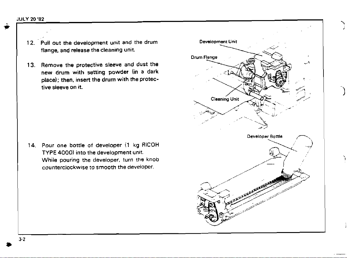
Pull out the development unit and the drum
12.
flange, and release the cleanlng unit.
Remove the protective sleeve and dust the
13.
new drum with setting powder (in
place): then, insert the drum with the protective sleeve on it.
14.
Pour one bottle of developer
TYPE
4000)
into the development unlt.
While pouring the developer. turn the knob
counterclockwise to smooth the
(1
a
dark
kg
RlCOH
deveioper.
Development
Unit
s:'
Developer
Battle
,
I
JULY
20 '82
2
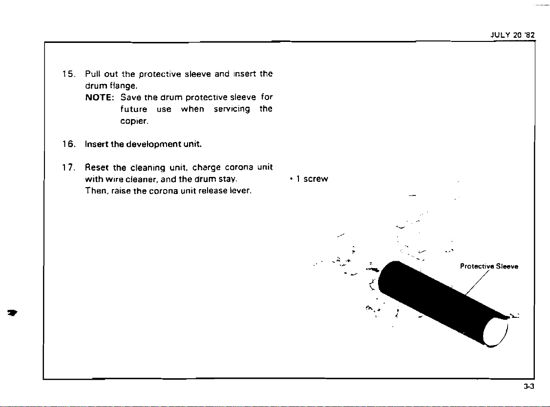
Pull out the protectlve sleeve and Insert the
15.
drum flange.
NOTE:
16.
Insert the development unit.
Reset the clean~ng unlt. charge corona unlt
17.
w~th wore cleaner. and the drum stav.
Then.
Save the drum protectlve sleeve for
future use when
copler.
ralse the corona unlt release lever.
serv~cing the
-
1
screw
-
6
.
JULY
M
'82
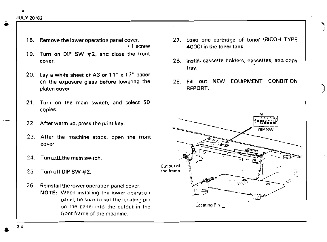
18.
Remove the lower operation panel cover.
.
I
screw
19.
Turn on DIP
cover.
20.
Lay a white sheet of
on the exposure glass before lowering the
platen cover. REPORT.
SW
#2.
and close the front
A3
or
1
1"
x
17"
Paper
27.
28.
29.
Load one cartridge of toner (RICOH TYPE
40001
in the toner tank.
Install cassette holders. cassettes. and copy
tray.
Fill out
NEW
EQUIPMENT CONDITION
Turn on the main switch. and select
copies.
After warm up, press the print key.
After the machine stops. open the front
cover.
Turnnffthe main sw~tch
Turn off DIP
Relnstail the lower ooerarlon panel cover
NOTE: When
SW
#2
~nstalltng the lower operatloll
panel. be sure to set the locatlng pln
on the panei Into the cutout in the
front frame of the
machlne.
50
Locating
1
pin-^
I
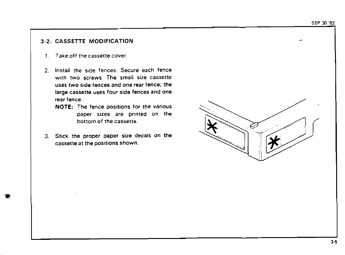
3-2.
CASSETTE MODIFICATION
1.
Take off the cassette cover
2.
Install the s~de fences. Secure each fence
w~th two screws. The small size cassette
uses two side fences and one rear fence; the
large cassette uses four side fences and one.
rear fence.
NOTE: The fence
paper sues are printed on the
bottom of the cassette.
Stick
3.
the proper paper size decals on the
cassette at the
pos~tions for the varlous
positions
shown.
SEP
30
'82
-
!
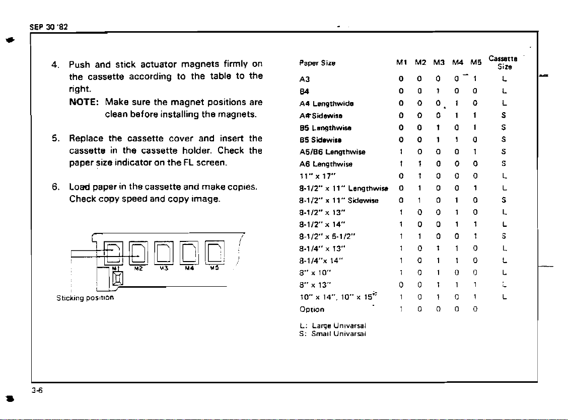
Push and stick actuator magnets firmly on
4.
the cassette according to the table to the
right.
NOTE:
Make sure the magnet positions are
clean before installing the magnets.
5.
Replace the cassette cover and insert the
cassette in the cassette holder. Check the
paper size indicator on the FL screen.
6.
Load paper in thecassette and make coples.
Check copy speed and copy image.
M1
Pawr
Sirs
A3
&)
A4 Lsngthwida
AQSidrmirs
85
Lsngthwisa
85
Saewiu
A5186
Lengthwise
A6
Langrhwira
ll"x17" 01000
8-llt" x 11"
8.112" x 11"
8-112"
8-112 x 14 10011
8-112" n 5-112" 11001
8-114" x 13" 10110
8.114~ 14" 10110
8"
x
8"
x
10 x 14". 10 x 15" 1 0
Option
L:
Lame
S:
Small
Lsngrhw~o
Sidewise
x
13"
10" 1010r)
13" 00111
Unlvarral
Unlvarral
M2 M3
0
0 0 0-1
00100
0
0 0.1 0
00011
00101
00110
10001
11000
0 1 0 0
0 1 0 1 0
10010
10000
M4
M5
Caizp
1
1
0
1
L
L
L
S
S
S
S
S
L
L
5
L
L
S
L
L
L
L
L

3-3.
1
KEY COUNTER HOLDER INSTALLATION
1.
For the FT4060 remove the right cover. - 4
For the
cover.
2.
Open the front cover and remove the right
inner cover.
3.
Remove the cover plate and fixing plate
from the key counter bracket.
4. Hold the fixing plate on the inside of the key
counter bracket and
holder.
Align the holes in the fixing plate with the
5.
mounting holes of the
and secure the key counter holder.
NOTE: This copier can use three types of
6.
Remove the shoRlng plug from the key
counter connector.
FT4030 remove the
insert the key counter
key
counter holder
the counter. Make sure to use the
in
correct holes
the fixtng plate.
csv
counter
2
-
3
screws
screws
screws
7.
Plug in the key counter holder.
8.
Reassemble the copier and check key counter operation.
Key
Counter
Holder
.
.
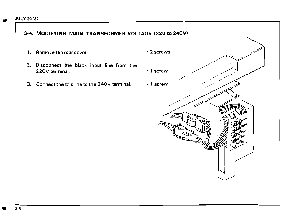
3-4.
MODIFYING MAIN TRANSFORMER VOLTAGE
1.
Remove the rear cover
2.
Disconnect the black input line from the
220V
terminal.
Connect the this line to the
3.
240V
terminal.
2
.
1
(220
tO240V)
screws
screw
\
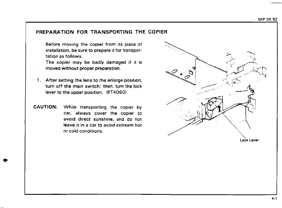
PREPARATION FOR TRANSPORTING THE COPIER
Before moving the copier from its place of
installation, be sure to prepare
tation as follows.
The copier may be badly damaged if
moved without proper preparation.
1.
After setting the lens to the enlarge position.
turn off the main
lever to the upper
CAUTION: While transporting the copler by
car. always cover the copier to
avoid direct sunshine. and do not
leave it in a car to avoid extream hot
or cold conditions.
sw~tch: then, turn the lock
pos~tion.
tt for transpor-
(FT4060)
it
is
,
Lock
Lever
SEP
30
**
JULY
20
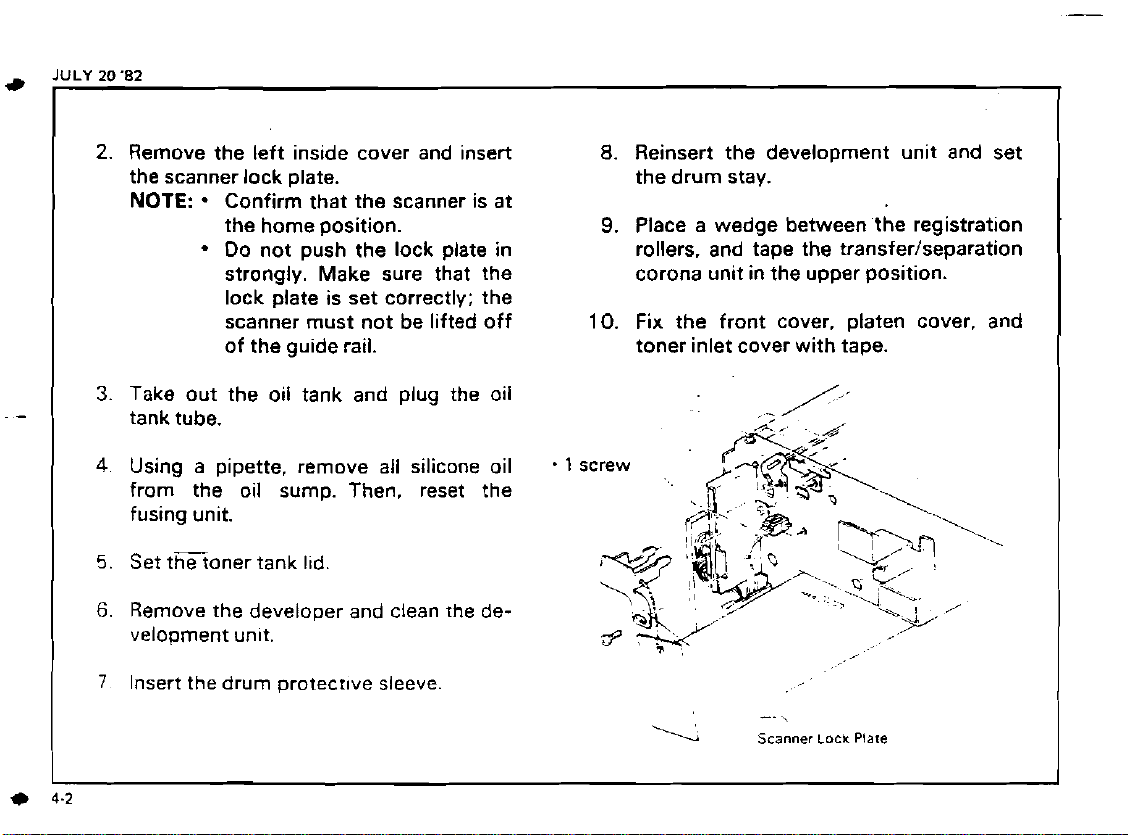
2.
3.
4.
5.
6.
7
(
1
'82
Remove the left inside cover and insert
the scanner lock plate.
NOTE:
Take out the oil tank and plug the oil
tank tube.
Using a pipette, remove all silicone oil
from the oil sump. Then, reset the
fusing unit.
Set tEoner tank l~d.
Remove the developer and clean the de-
velopment
Insert the drum protectwe sleeve
.
Confirm that the scanner is at
the home position.
Do not push the lock plate in
strongly. Make sure that the
lock plate is set correctly; the
scanner must not be lifted off
of the guide rail.
unlt.
.
10.
1
screw
8.
Reinsert the development unit and set
the drum stay.
9.
Place a wedge between the registration
rollers. and tape the
corona unit in the upper position.
Fix the front cover. platen cover. and
toner inlet cover with tape.
'Y
--
Scanner
transferlseparation
,
\
Lock
Plare
-.
I
I
*
-
.
,?
._k*.'.
...?$*.;-
,:?h
-.
..I*.<
...
,.;~,.
.,
It
.q%%..ey
.
.
~.
.
-.
.
..
,+-..
.
:-,
.r
::?-
.-
,.(:-..-
I
:e*tx*$y;&,
;
.
.
,
,.
.
'L5
..
-
.
,.'
-. .
~f.
-
=
-
:.
:;,
..
,.,:
.
.Z
-...
.I.
-*
h..
:-..c.
r:,.
.:.s>:
.
.
-
,
,
.
:,
'..
.?
--
.;:
&~$:*~4:#y$*$4::.
.
%.
:.d&;
kaK$<+<.*,&&&::
,
,
. . .
.
'.',~.2
.;:+!'.;-.
.. .
..,..
1
.
.-<.;
:'Y
.
.
:
'
.
:>,
...
1.:,
T
.
.-.
.
.
.
,,<
..:.
,.
.-.
.:
3.
,
,
.
.
.
.
. . .".
.,
41-
,
,
LI.
-
;:
,
,
"L
.
.. .
:
.
.
.
.
.
...
.
--
.
,
-
..
;.
*.
..
.
5-1.
POINTS TO
Drum Charge
1.
2.
3.
Exposure
1.
2.
3.
REMEMBER
The corona wlres should be cleaned at
servtce call by sliding the corona
every
4.
unit or with dry cloth.
Do not use emery paper or alcohol for
wire cleaning.
Do not touch the corona wires with oily
Launa
used to
a. Scanner Guide Rod (cleaning)
b. Scanner Guide Rod Pads (Lubrication)
011
or an equivalent oil should be
lubr~cate or clean the following
hands. c. Scanner Guide Plate
Make sure that the corona wires are correctly inserted between the cleaner pads.
ILubrication/Cleaning)
d. Lens Drive Screw Shaft (Lubrication)
CAUTI0N:Do not use silicone oil or any
DO not adjust the follow~ng parts:
a : First and second scanner height ad-
lusting cams.
b
:
Scanner Guide Plate
:
Lens AXIS Adjusting Cam
c
:
Lens Posltion Adjusting Screw.
d
:
Fourth Mirror Angle Adjusting Screw.
e
11
screw each1 er and a dry cloth.
(3
screws1
(1
screw)
The scanner home sensor and the lens
home sensor should be
when iewly
installed.
adlusted only
.
,
5.
Clean the exposure glass with glass clean-
6.
Do not touch the following parts with
bare hands:
a.
Reflectors
b. Exposure Glass
c. Mirrors and Lens
7.
DO not adjust the
other kind of
VR
..
on the optics PCB.
Do not bend or damage the lens support
plate or the mylar
strtp.
011.
JULY
20
82
-
~
..
5
 Loading...