


MCD-909
DVD Micro Theatre
TABLE OF CONTENTS
3141 785 33540
DB 0908
2009
MCD909
Location of PC Boards ............................................. 1-1
Electronic Specification
............................................. 1-2
Measurement Setup ................................................ 1-3
Service Aids............................................................... 1-4
Software Version Check & Upgrade ........................ 2-1
Malfuction Check Chart ............................................. 2-2
Disassembly Diagram................................................ 3-1
Block Diagram ......................................................... 4-1
Wiring Diagram ......................................................... 5-1
Display Board ............................................................... 6
Circuit diagram ...................................................... 6-1
Layout diagram ...................................................... 6-2
Prepositive Board ......................................................... 7
Circuit diagram ...................................................... 7-1
Layout diagram ...................................................... 7-2
AMP Board .................................................................. 8
Circuit diagram ...................................................... 8-1
Layout diagram ...................................................... 8-2
ECO Control Board Diagram ....................................... 9
Small Board Diagram ...................................................10
Decoder Board ............................................................11
Circuit diagram ....................................... 11-1 to 11-8
Layout diagram ..................................................... 11-9
Exploded View ............................................................12
DVD Exploded View ............................................. 12-1
AMP Exploded View ............................................. 12-2
Service Partlist .......................................... 13-1 to 13-2
Factory Partlist .......................................... 14-1 to 14-6
Version 1.0
Location of PC Boards
1-1
Type /Versions:
Features
Board in used:
MCD909
Service policy
BUTTON BOARD
AMP BOARD
ENCODER BOARD
VACUUM TUBE LAMP BOARD
PREPOSITIVE BOARD
DISPLAY BOARD
USB BOARD
ECO-POWER BOARD
LAMP BOARD
DECODER BOARD
* TIPS : C -- Component Level Repair.
M -- Module Level Repair
-- Used
/55
/55
/58
/58
/61
/61
/79
/79
/93
/93
/94
/94
/96
/96
/98
/98
/37
/37
/12
/12
/05
/05
Feature diffrence
RDS
TDS
VOLTAGE SELECTOR
ECO STANDBY - DARK
M
C
C
M
M
M
M
C
M
Type /Versions:
MCD909
DISPLAY BOARD
USB BOARD
DECODER BOARD
SCART BOARD
LAMP BOARD
PUSH KEY BOARD
VACUUM TUBE LAMP BOARD
ENCODER BOARD
LAMP BOARD
(Same location on the other side)
(Same location on the other side)
AMP BOARD
M

1-2
Specifications
AMPLIFIER
Rated Output Power ............................ 2 x 75W RMS
S/N ..............................................................>=65dBA
Frequency response .................... 40Hz-20KHz,±3dB
Aux Input ...................................... 0.5V RMS 47kohm
DISC
Laser Type ........................................ Semiconductor
Disc Diameter ............................................ 12cm/8cm
Support Disc ..............................................................
............ DVD,Divx,CD-DA,CD-R,CD-RW,MP3,WMA
Audio DAC........................................ 24Bits / 44.1kHz
Total Harmonic Distortion ...... 4Hz - 20kHz (44.1kHz)
S/N ................................................................>65dBA
TUNER
FM Tuning Range ............................ 87.5 – 108 MHz
Tuning grid ............................................ 50K/100KHz
Sensitivity
- Mono,26dB S/N .............................................. 5uV
- Stereo,46dB S/N ........................................ 100uV
Selectivity ........................................................ >33dB
Image Rejection ..........................................25-30 dB
Total Harmonic Distortion .................................. 2-3%
S/N ................................................................>33dBA
SPEAKERS
Speaker Impedance .......................................... 4ohm
Speaker Driver,base ........................................ 5 1/4"
Speaker Driver,tweeter ...................................... RT-2
Frequency response .......................... 60Hz - 20 KHz
GENERAL INFORMATION
Total Output Power ................................ 150 W RMS
AC Power .............................. 220V-230V / 50Hz(/12)
240V/50Hz(/79).220V / 50Hz(/93).220V / 60Hz(/61)
Operation Power Consumption .......................... 85W
Standby Pwer Consumption .............................. <4W
Eco Standby Pwer Consumption............................ NA
USB Direct................................................ Version 1.1
Dimensions
- Main unit (w x h x d) ..................280X130X290mm
- Speaker box(w x h x d) ............ 185x305x225mm
Weight
- With Packing ................................................24.5 KG
- Main unit ...................................................... 6.78KG
- Speaker box ....................................................14KG
- Subwoofer ............................................................NA
*
Specifications and external appearance
are subject to change without notice.
1-3
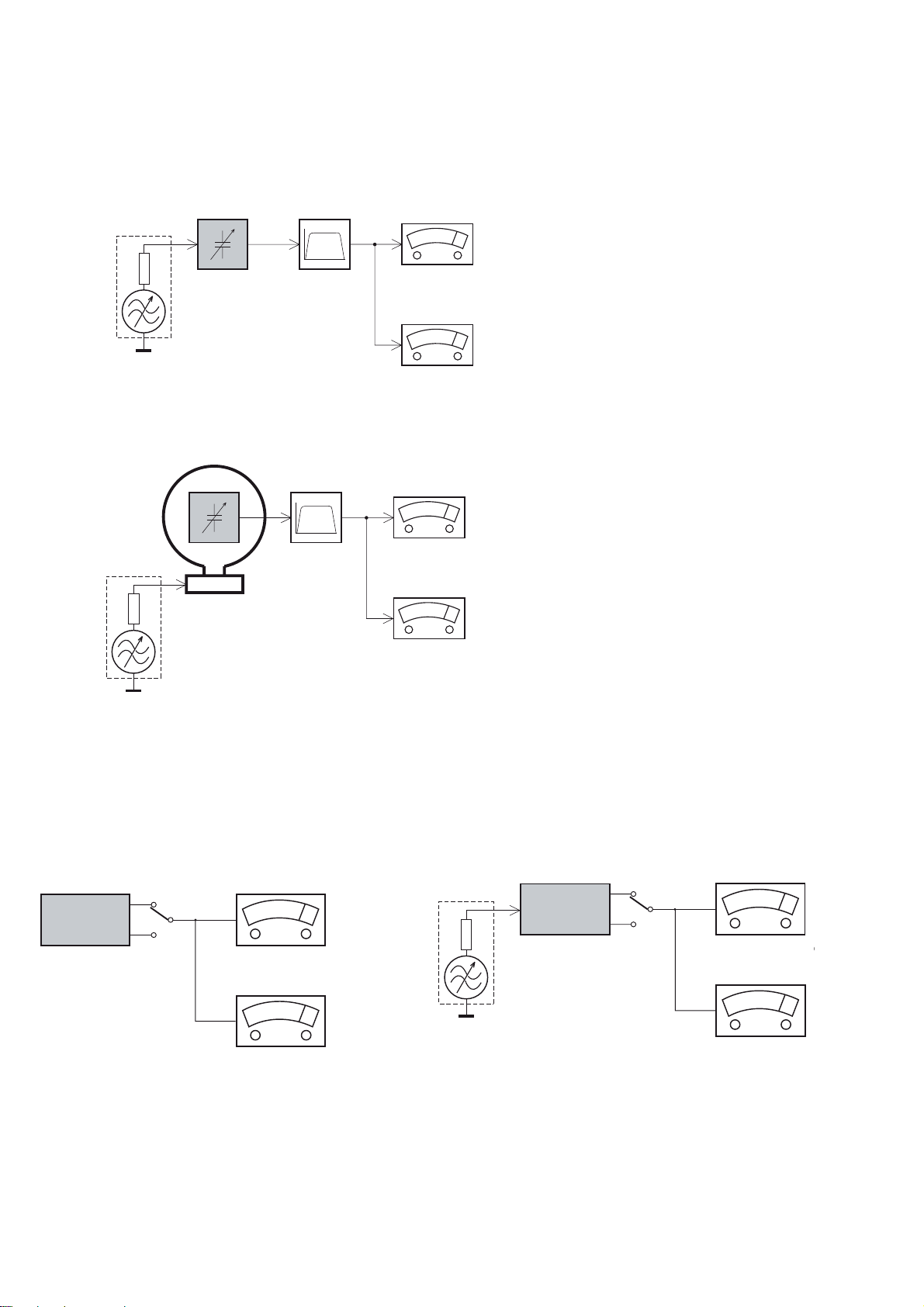
LF Generator
e.g. PM5110
Recorder
Use Universal Test Cassette CrO2 SBC419 4822 397 30069
LEVEL METER
e.g. Sennheiser UPM550
with FF-filter
S/N and distortion met
e
e.g. Sound Technology ST170
L
R
DUT
or Universal Test Cassette
Fe SBC420 4822 397 30071
LEVEL METER
e.g. Sennheiser UPM550
-
S/N and distortion meter
e.g. Sound Technology ST1700B
L
R
DUT
CD
Use Audio Signal Disc
(replaces test disc 3)
SBC429 4822 397 30184
Bandpass
250Hz-15kHz
e.g. 7122 707 48001
LF Voltmeter
e.g. PM2534
DUT
S/N and distortion meter
e.g. Sound Technology ST1700B
Frame aerial
e.g. 7122 707 89001
Tuner AM (MW,LW)
To avoid atmospheric interference all AM-measurements have to be carried out in a Faraday´s cage.
Use a bandpass filter (or at least a high pass filter with 250Hz) to eliminate hum (50Hz, 100Hz).
RF Generator
e.g. PM5326
Ri=50:
Bandpass
250Hz-15kHz
e.g. 7122 707 48001
LF Voltmeter
e.g. PM2534
DUT
RF Generator
e.g. PM5326
S/N and distortion meter
e.g. Sound Technology ST1700B
Use a bandpass filter to eliminate hum (50Hz, 100Hz) and disturbance from the pilottone (19kHz, 38kHz).
Ri=50:
Tuner FM
MEASUREMENT SETUP
1-4
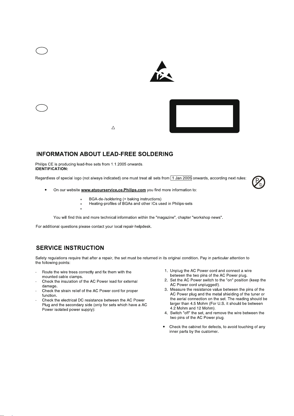
SERVICE AIDS
GB
WARNING
All ICs and many other semi-conductors are
susceptible to electrostatic discharges (ESD).
Careless handling during repair can reduce life
drastically.
When repairing, make sure that you are
connected with the same potential as the mass
of the set via a wrist wrap with resistance.
Keep components and tools also at this
potential.
ESD
CLASS 1
LASER PRODUCT
GB
Safety regulations require that the set be restored to its original
condition and that parts which are identical with those specified,
be used
Safety components are marked by the symbol
!
.
Lead free
Set remains closed!
N
Y
Play a CD
for at least 10 minutes
Y
playability
ok ?
N
playability
ok ?
add Info for customer
"SET OK"
check playability
N
Y
playability
ok ?
check playability
check playability
return set
Customer complaint
"CD related problem"
"fast" lens cleaning
1
2
3
For flap loaders (= access to CD drive possible)
cleaning method
4 is recommended
INSTRUCTIONS ON CD PLAYABILITY
1-
Exchange CDM
1 - 4 For description - see following pages
1
PLAYABILITY CHECK
For sets which are compatible with CD-RW discs
use CD-RW Printed Audio Disc ....................7104 099 96611
TR 3 (Fingerprint)
TR 8 (600μ Black dot) maximum at 01:00
• playback of these two tracks without audible disturbance
playing time for: Fingerprint t10seconds
Black dot from 00:50 to 01:10
• jump forward/backward (search) within a reasonable time
For all other sets
use CD-DA SBC 444A..................................4822 397 30245
TR 14 (600μ Black dot) maximum at 01:15
TR 19 (Fingerprint)
TR 10 (1000μ wedge)
• playback of all these tracks without audible disturbance
playing time for: 1000μ wedge t10seconds
Fingerprint t10seconds
Black dot from 01:05 to 01:25
• jump forward/backward (search) within a reasonable time
2
CUSTOMER INFORMATION
It is proposed to add an addendum sheet to the set which
informs the customer that the set has been checked
carefully - but no fault was found.
The problem was obviously caused by a scratched, dirty or
copy-protected CD. In case problems remain, the customer
is requested to contact the workshop directly.
The lens cleaning (method 3) should be mentioned in the
addendum sheet.
The final wording in national language as well as the printing
is under responsibility of the Regional Service Organizations.
4
LIQUID LENS CLEANING
Because the material of the lens is synthetic and coated
with a special anti-reflectivity layer, cleaning must be done
with a non-aggressive cleaning fluid. It is advised to use
“Cleaning Solvent
The actuator is a very precise mechanical component and
may not be damaged in order to guarantee its full function.
Clean the lens gently (don’t press too hard) with a soft and
clean cotton bud moistened with the special lens cleaner.
The direction of cleaning must be in the way as indicated in
the picture below.
Before touching the lens it is advised to clean the
surface of the lens by blowing clean air over it.
This to avoid that little particles make scratches on
the lens.
INSTRUCTIONS ON CD PLAYABILITY
1-

2-1
Software Version Check & Upgrade
Upgrade software
Software check
Press the “display” button quartic continuously on remote control,
display showing as below:
1.Download the software from Philips support website
2.Put in the Software CD Disc or USB,
untill hear a long ding voice while it is loading. Software
upgrade finish.
http://www.philips.com/support
Vxx dyyyy
2-2
Malfunction follow check chart
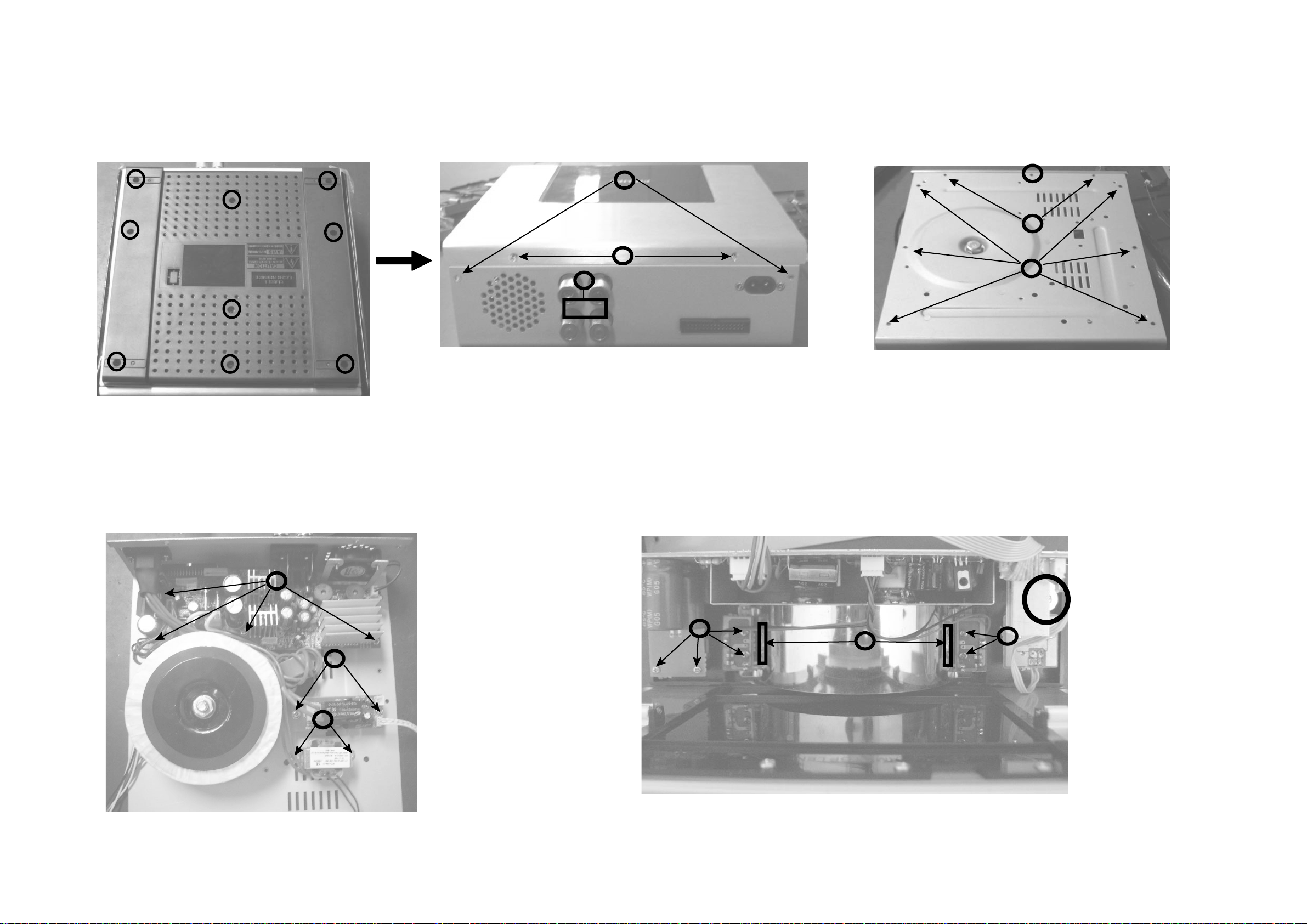
Disassembly Diagram
-- DVD Part
3-1
3-1
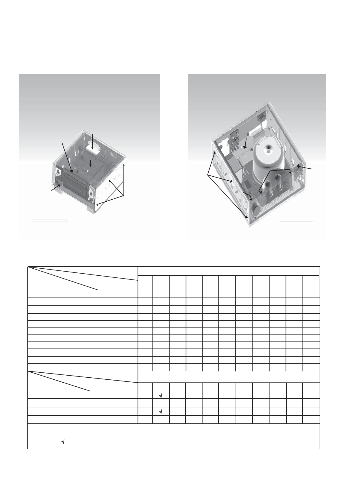
A. Loosen screws 9 PCS 3 X 6 BMTT
to remove bottom chassis
B.Loosen screws 2 PCS 3 X 6 FMTT
C.Loosen screws 5 PCS 3 X 10 BA
D.Loosen screws 2 PCS 3 X 10 BA
E.Loosen screws 2 PCS 3 X 10 BTH
F. Loosen screws 1 PCS 3 X 4 FMTT
G.Loosen screws 2 PCS 3 X 6 BMTT
H.Loosen screws 6 PCS 3 X 10 BTH
I . Loosen screws 5 PCS3 X 6 BM
J. Loosen 6PCS 3×12BTH screws
to dissassembly mechanism
K. Loosen 9PCS 2.6×8PA screws
to disassembly display board
B
C
D
E
F
G
H
3-2
3-2
Disassembly Diagram
-- AMP Part
B.Loosen 2 PCS 3 X 6 FMTT screws
C.Loosen 2 PCS 3 X 10 BMTT screws
D.Loosen 2 PCS 3 X 10 BTH screws
F. Loosen 1 PCS 3 X 4 FMTT screws
G. Loosen 2 PCS 3 X 6 BMTT screws
H. Loosen 6 PCS 3 X 10 BTH screws
I. Loosen 4 PCS 3 X 6 BM screws
J. Loosen 2 PCS 3 X 4 BMTT screws
K. Loosen 2 PCS 3 X 6 BM screws
L. Loosen 10 PCS 2.6X 8 PA screws
M. Loosen 1 PCS 3 X 10PA
screws
A. Loosen screws 9 PCS 3 X 6 BMTT
to remove bottom chassis
B
C
D
F
G
H
I
J
K
L
L
M
L
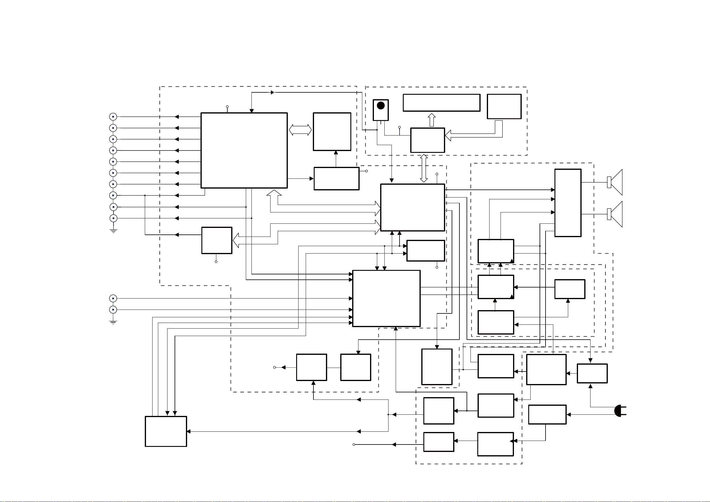
4-1
4-1
AUX-R
AUX-R IN
AUX-L
AUX-L IN
RED
ROUT
VIDEO
V-OUT
S-VIDEO
S-V OUT
COAXIAL
OPTICAL
GREEN
GR OUT
BLUE
B OUT
REM
1
GND
2
Vcc
3
REM-SENSOR
CPU5V
CPU5V
CPU5V
DVD5V
AC230
STANDBY
CPU5V
DVD5V
DVD ON/OFF
TUNER-RIN
AUX-R IN
AUX-L IN
D-FL
D-FR
SDA
SCL
FR
FL
FR
FL
STANDBY
MUTE
+vs
-vs
+vs
-vs
D-FL
D-FR
FR
FL
+vs
-vs
+12V
FM+5V
TUNER-LIN
TUNER-RIN
TUNER-LIN
DVD ON/OFF
MCU
R5R0C028
SM9435A
SWITCH
CONTROL
DVD POWER
PT2314
TDA8920
7812
24C02
MEPG2
BLOCK
MT1389FE
VFD KEY
CONTROL
MECHANISM
DVD
TUNER
BLOCK
IC:4705
POWER
CONTROL
SWITCH
VS1101
SELENIUM
FILTER
DVD
POWER
TRANSFORMER
FM+5V
HDMI/CEC
DTA9950
CEC
CEC3.3V
Loader motor driver
CD5954
DVD5V
DVD LINE-R
DVD LINE-R
DVD LINE-L
DVD LINE-L
CEC
SWITCH
POWER
TRANSFORMER
POWER
7805
POWER ON/OFF
POWER ON/OFF
SELENIUM
FILTER
MCU
SELENIUM
FILTER
AMP
SELENIUM
FILTER
TUBE
12AX7
TL072
FR
FL
PT6311
HDMI
Block Diagram
Decode Board
Displayboard
AMP Board
Prepositive
Board
 Loading...