


 Loading...
Obstetrical Care
S E R V I C E G U I D E
Series 50 A
M1351A
Series 50 IP-2
M1353A
Fetal/Maternal Monitors
F E T A L M O N I T O R I N G
Printed in Germany 10/04
*M1353-9000K*
Part Number M1353-9000K
4512 610 04691
S

Series 50 Fetal Monitors
Series 50 A (M1351A)
Series 50 IP-2 (M1353A)
S E R V I C E A N D I N S T A L L A T I O N G U I D E
M1353-9000K
Printed in Germany October 2004

Notice
Philips makes no warranty of any kind with regard to this material, including, but not limited to, the implied warranties of merchantability and fitness for a particular purpose. Philips Medical Systems shall not be liable for errors contained herein or for incidental or consequential damages in connection with the furnishing, performance or use of this material.
This document contains proprietary information that is protected by copyright. All rights are reserved. No part of this document may be photocopied, reproduced or translated to another language without prior written consent of Philips Medical Systems.
The information contained in this document is subject to change without notice.
Philips assumes no responsibility for the use or reliability of its software on equipment that is not furnished by Philips.
Purchase of this instrument confers no express or implied license under any Nellcor patent or copyright to use this instrument with any fetal oximetry sensor that is not manufactured or licensed by Nellcor.
Dinamap is a trademark of General Electric.Press-Mate is a trademark of the COLIN Corporation.
Federal Law (US) restricts this device to sale by or on the order of a physician.
Caution
Failure on the part of the responsible individual hospital or institution employing the use of this equipment to implement a satisfactory maintenance schedule may cause undue equipment failure and possible health hazards.
ii

Printing History
New editions are complete revisions of the manual. Update packages, which are issued between editions, contain additional and replacement pages to be added to the manual. The dates on the title page change only when a new edition or a new update is published.
Edition 1: June 1992
Edition 2: August 1993
Edition 3: February 1995
Edition 4: March 1997
Edition 5: February 1998
Edition 6: May 2000
Edition 7: April 2002
Edition 8: October 2004
1990-2004 Koninklijke Philips Electronics N.V.
All Rights Reserved.
iii
iv
Contents
1. General Information. . . . . . . . . . . . . . . . . . . . . . . . . . . . . . . . . . . . . . . . . . . . . . . . . . . . . . . . . 1
Introduction . . . . . . . . . . . . . . . . . . . . . . . . . . . . . . . . . . . . . . . . . . . . . . . . . . . . . . . . . . . . . . . . . . . . . . . . . . . . . . 1 Who Should Read This Guide . . . . . . . . . . . . . . . . . . . . . . . . . . . . . . . . . . . . . . . . . . . . . . . . . . . . . . . . . . . . 1 What to do Next . . . . . . . . . . . . . . . . . . . . . . . . . . . . . . . . . . . . . . . . . . . . . . . . . . . . . . . . . . . . . . . . . . . . . . . 1 Repair Strategy . . . . . . . . . . . . . . . . . . . . . . . . . . . . . . . . . . . . . . . . . . . . . . . . . . . . . . . . . . . . . . . . . . . . . . . . . . . 1 Conventions and Symbols Used in this Guide. . . . . . . . . . . . . . . . . . . . . . . . . . . . . . . . . . . . . . . . . . . . . . . . . . . . 2 Initial Inspection . . . . . . . . . . . . . . . . . . . . . . . . . . . . . . . . . . . . . . . . . . . . . . . . . . . . . . . . . . . . . . . . . . . . . . . . . . 3 Claims for Damage . . . . . . . . . . . . . . . . . . . . . . . . . . . . . . . . . . . . . . . . . . . . . . . . . . . . . . . . . . . . . . . . . . . . . 3 Repacking . . . . . . . . . . . . . . . . . . . . . . . . . . . . . . . . . . . . . . . . . . . . . . . . . . . . . . . . . . . . . . . . . . . . . . . . . . . . 3 Overview . . . . . . . . . . . . . . . . . . . . . . . . . . . . . . . . . . . . . . . . . . . . . . . . . . . . . . . . . . . . . . . . . . . . . . . . . . . . . . . . 4 Major Keys and Parts at a Glance . . . . . . . . . . . . . . . . . . . . . . . . . . . . . . . . . . . . . . . . . . . . . . . . . . . . . . . . . . . . . 5 Monitor Control and Display Panel . . . . . . . . . . . . . . . . . . . . . . . . . . . . . . . . . . . . . . . . . . . . . . . . . . . . . . . . . . . . 7 M1351A Single Ultrasound Model . . . . . . . . . . . . . . . . . . . . . . . . . . . . . . . . . . . . . . . . . . . . . . . . . . . . . . . . 7 M1351A Dual Ultrasound Twins Model . . . . . . . . . . . . . . . . . . . . . . . . . . . . . . . . . . . . . . . . . . . . . . . . . . . . 7 M1353A Model . . . . . . . . . . . . . . . . . . . . . . . . . . . . . . . . . . . . . . . . . . . . . . . . . . . . . . . . . . . . . . . . . . . . . . . 8 Accessories. . . . . . . . . . . . . . . . . . . . . . . . . . . . . . . . . . . . . . . . . . . . . . . . . . . . . . . . . . . . . . . . . . . . . . . . . . . . . . . 9 Series 50 A (M1351A) . . . . . . . . . . . . . . . . . . . . . . . . . . . . . . . . . . . . . . . . . . . . . . . . . . . . . . . . . . . . . . . . . . 9 Series 50 IP-2 (M1353A) . . . . . . . . . . . . . . . . . . . . . . . . . . . . . . . . . . . . . . . . . . . . . . . . . . . . . . . . . . . . . . . . 9 Documentation . . . . . . . . . . . . . . . . . . . . . . . . . . . . . . . . . . . . . . . . . . . . . . . . . . . . . . . . . . . . . . . . . . . . . . . 10 Options . . . . . . . . . . . . . . . . . . . . . . . . . . . . . . . . . . . . . . . . . . . . . . . . . . . . . . . . . . . . . . . . . . . . . . . . . . . . . 11
2. Technical Specifications . . . . . . . . . . . . . . . . . . . . . . . . . . . . . . . . . . . . . . . . . . . . . . . . . . . . . 13
Monitor. . . . . . . . . . . . . . . . . . . . . . . . . . . . . . . . . . . . . . . . . . . . . . . . . . . . . . . . . . . . . . . . . . . . . . . . . . . . . . . . . 13 Power Requirements . . . . . . . . . . . . . . . . . . . . . . . . . . . . . . . . . . . . . . . . . . . . . . . . . . . . . . . . . . . . . . . . . . . 13 Environment . . . . . . . . . . . . . . . . . . . . . . . . . . . . . . . . . . . . . . . . . . . . . . . . . . . . . . . . . . . . . . . . . . . . . . . . . 13 Weight and Dimensions . . . . . . . . . . . . . . . . . . . . . . . . . . . . . . . . . . . . . . . . . . . . . . . . . . . . . . . . . . . . . . . . 13 Displays . . . . . . . . . . . . . . . . . . . . . . . . . . . . . . . . . . . . . . . . . . . . . . . . . . . . . . . . . . . . . . . . . . . . . . . . . . . . 14 Inputs . . . . . . . . . . . . . . . . . . . . . . . . . . . . . . . . . . . . . . . . . . . . . . . . . . . . . . . . . . . . . . . . . . . . . . . . . . . . . . 14 Recorder . . . . . . . . . . . . . . . . . . . . . . . . . . . . . . . . . . . . . . . . . . . . . . . . . . . . . . . . . . . . . . . . . . . . . . . . . . . . 15 Self-Test Facilities . . . . . . . . . . . . . . . . . . . . . . . . . . . . . . . . . . . . . . . . . . . . . . . . . . . . . . . . . . . . . . . . . . . . 16 Combined Interface Module . . . . . . . . . . . . . . . . . . . . . . . . . . . . . . . . . . . . . . . . . . . . . . . . . . . . . . . . . . . . . 16 Modem Interface Module . . . . . . . . . . . . . . . . . . . . . . . . . . . . . . . . . . . . . . . . . . . . . . . . . . . . . . . . . . . . . . . 16 Remote Event Marker (15249A) . . . . . . . . . . . . . . . . . . . . . . . . . . . . . . . . . . . . . . . . . . . . . . . . . . . . . . . . . 16
Transducers and Cables . . . . . . . . . . . . . . . . . . . . . . . . . . . . . . . . . . . . . . . . . . . . . . . . . . . . . . . . . . . . . . . . . . . . 17 Brown Toco Transducer (M1355A) . . . . . . . . . . . . . . . . . . . . . . . . . . . . . . . . . . . . . . . . . . . . . . . . . . . . . . . 17 Blue Toco Transducer (M1355A). . . . . . . . . . . . . . . . . . . . . . . . . . . . . . . . . . . . . . . . . . . . . . . . . . . . . . . . . 17
Brown Ultrasound Transducer (M1356A) . . . . . . . . . . . . . . . . . . . . . . . . . . . . . . . . . . . . . . . . . . . . . . . . . . 17 Blue1 Ultrasound Transducer (M1356A) . . . . . . . . . . . . . . . . . . . . . . . . . . . . . . . . . . . . . . . . . . . . . . . . . . . 17
DECG Transducer (M1357A) . . . . . . . . . . . . . . . . . . . . . . . . . . . . . . . . . . . . . . . . . . . . . . . . . . . . . . . . . . . 18 MECG Transducer (M1359A) . . . . . . . . . . . . . . . . . . . . . . . . . . . . . . . . . . . . . . . . . . . . . . . . . . . . . . . . . . . 18 DECG/MECG Patient Module (M1364A) . . . . . . . . . . . . . . . . . . . . . . . . . . . . . . . . . . . . . . . . . . . . . . . . . . 18 IUP Quartz Transducer (1290C option J05) . . . . . . . . . . . . . . . . . . . . . . . . . . . . . . . . . . . . . . . . . . . . . . . . . 19 IUP Pressure Transducer (CPJ840J5) . . . . . . . . . . . . . . . . . . . . . . . . . . . . . . . . . . . . . . . . . . . . . . . . . . . . . . 20
3. Installing the Monitor. . . . . . . . . . . . . . . . . . . . . . . . . . . . . . . . . . . . . . . . . . . . . . . . . . . . . . . 21
Fitting the Monitor to a Surface . . . . . . . . . . . . . . . . . . . . . . . . . . . . . . . . . . . . . . . . . . . . . . . . . . . . . . . . . . . . . . 21 Fitting the Monitor to the Angle Mount. . . . . . . . . . . . . . . . . . . . . . . . . . . . . . . . . . . . . . . . . . . . . . . . . . . . . . . . 21 Fitting the Monitor to a Wall . . . . . . . . . . . . . . . . . . . . . . . . . . . . . . . . . . . . . . . . . . . . . . . . . . . . . . . . . . . . . . . . 22 Wall Mount Dimensions . . . . . . . . . . . . . . . . . . . . . . . . . . . . . . . . . . . . . . . . . . . . . . . . . . . . . . . . . . . . . . . . 22 Fitting the Paper Take-Up Tray . . . . . . . . . . . . . . . . . . . . . . . . . . . . . . . . . . . . . . . . . . . . . . . . . . . . . . . . . . . . . . 23
Contents |
v |
Cart-mounted Paper Tray . . . . . . . . . . . . . . . . . . . . . . . . . . . . . . . . . . . . . . . . . . . . . . . . . . . . . . . . . . . . . . . 23
Carts . . . . . . . . . . . . . . . . . . . . . . . . . . . . . . . . . . . . . . . . . . . . . . . . . . . . . . . . . . . . . . . . . . . . . . . . . . . . . . . . . . . 24
Fitting the Barcode Reader Holder . . . . . . . . . . . . . . . . . . . . . . . . . . . . . . . . . . . . . . . . . . . . . . . . . . . . . . . . . . . 24
4. Configuring the Monitor . . . . . . . . . . . . . . . . . . . . . . . . . . . . . . . . . . . . . . . . . . . . . . . . . . . . 25
Introduction. . . . . . . . . . . . . . . . . . . . . . . . . . . . . . . . . . . . . . . . . . . . . . . . . . . . . . . . . . . . . . . . . . . . . . . . . . . . . . 25 Configuring the Monitor Using Pushbuttons . . . . . . . . . . . . . . . . . . . . . . . . . . . . . . . . . . . . . . . . . . . . . . . . . . . . 26 Examples: How to Change the Time Format and IUP Format using Pushbuttons . . . . . . . . . . . . . . . . . . . . 28 Configuring the Monitor Using Barcodes . . . . . . . . . . . . . . . . . . . . . . . . . . . . . . . . . . . . . . . . . . . . . . . . . . . . . . 29 Configuring the Monitor Using a PC . . . . . . . . . . . . . . . . . . . . . . . . . . . . . . . . . . . . . . . . . . . . . . . . . . . . . . . . . . 29 Installing the Service Program. . . . . . . . . . . . . . . . . . . . . . . . . . . . . . . . . . . . . . . . . . . . . . . . . . . . . . . . . . . . 30 Connecting the PC to the Monitor . . . . . . . . . . . . . . . . . . . . . . . . . . . . . . . . . . . . . . . . . . . . . . . . . . . . . . . . . 31 Loading the Service Program . . . . . . . . . . . . . . . . . . . . . . . . . . . . . . . . . . . . . . . . . . . . . . . . . . . . . . . . . . . . 31 Using the Service Program . . . . . . . . . . . . . . . . . . . . . . . . . . . . . . . . . . . . . . . . . . . . . . . . . . . . . . . . . . . . . . 31 Error Log Messages . . . . . . . . . . . . . . . . . . . . . . . . . . . . . . . . . . . . . . . . . . . . . . . . . . . . . . . . . . . . . . . . . . . . . . . 44
5. Setting Time, Date, and Paper Speed . . . . . . . . . . . . . . . . . . . . . . . . . . . . . . . . . . . . . . . . . . 47
Time and Date. . . . . . . . . . . . . . . . . . . . . . . . . . . . . . . . . . . . . . . . . . . . . . . . . . . . . . . . . . . . . . . . . . . . . . . . . . . . 47
Paper Speed. . . . . . . . . . . . . . . . . . . . . . . . . . . . . . . . . . . . . . . . . . . . . . . . . . . . . . . . . . . . . . . . . . . . . . . . . . . . . . 48
6. Theory of Operation . . . . . . . . . . . . . . . . . . . . . . . . . . . . . . . . . . . . . . . . . . . . . . . . . . . . . . . . 49
System Overview . . . . . . . . . . . . . . . . . . . . . . . . . . . . . . . . . . . . . . . . . . . . . . . . . . . . . . . . . . . . . . . . . . . . . . . . . 49 Booting and Self Tests . . . . . . . . . . . . . . . . . . . . . . . . . . . . . . . . . . . . . . . . . . . . . . . . . . . . . . . . . . . . . . . . . . . . . 50 Front End Board . . . . . . . . . . . . . . . . . . . . . . . . . . . . . . . . . . . . . . . . . . . . . . . . . . . . . . . . . . . . . . . . . . . . . . . . . . 52 M1351A (M1353-66501 and M1353-66511) . . . . . . . . . . . . . . . . . . . . . . . . . . . . . . . . . . . . . . . . . . . . . . . 52 M1353A (M1353-66512) . . . . . . . . . . . . . . . . . . . . . . . . . . . . . . . . . . . . . . . . . . . . . . . . . . . . . . . . . . . . . . . 52 Frontend Board for M1353A (M1350-66517) . . . . . . . . . . . . . . . . . . . . . . . . . . . . . . . . . . . . . . . . . . . . . . . 54 Power Supply Board (M1353-66502) . . . . . . . . . . . . . . . . . . . . . . . . . . . . . . . . . . . . . . . . . . . . . . . . . . . . . . . . . 55 CPU Board (M1353-66503 and M1353-66513) . . . . . . . . . . . . . . . . . . . . . . . . . . . . . . . . . . . . . . . . . . . . . . . . . 56 CPU Board M1353-66503 . . . . . . . . . . . . . . . . . . . . . . . . . . . . . . . . . . . . . . . . . . . . . . . . . . . . . . . . . . . . . . . 56 CPU Board M1353-66513 . . . . . . . . . . . . . . . . . . . . . . . . . . . . . . . . . . . . . . . . . . . . . . . . . . . . . . . . . . . . . . . 56 Display Board (M1350-66520) . . . . . . . . . . . . . . . . . . . . . . . . . . . . . . . . . . . . . . . . . . . . . . . . . . . . . . . . . . . . . . 58 Recorder Interface Board (M1353-66510) . . . . . . . . . . . . . . . . . . . . . . . . . . . . . . . . . . . . . . . . . . . . . . . . . . . . . 59 Interface Boards . . . . . . . . . . . . . . . . . . . . . . . . . . . . . . . . . . . . . . . . . . . . . . . . . . . . . . . . . . . . . . . . . . . . . . . . 60 Combined Interface Board. . . . . . . . . . . . . . . . . . . . . . . . . . . . . . . . . . . . . . . . . . . . . . . . . . . . . . . . . . . . . . . 60 Modem Interface Board . . . . . . . . . . . . . . . . . . . . . . . . . . . . . . . . . . . . . . . . . . . . . . . . . . . . . . . . . . . . . . . . . 63
7. Tests and Error Messages . . . . . . . . . . . . . . . . . . . . . . . . . . . . . . . . . . . . . . . . . . . . . . . . . . . 65
Service Philosophy . . . . . . . . . . . . . . . . . . . . . . . . . . . . . . . . . . . . . . . . . . . . . . . . . . . . . . . . . . . . . . . . . . . . . . . . 65
Overview of the Service Tests . . . . . . . . . . . . . . . . . . . . . . . . . . . . . . . . . . . . . . . . . . . . . . . . . . . . . . . . . . . . 65
Performance Assurance Tests . . . . . . . . . . . . . . . . . . . . . . . . . . . . . . . . . . . . . . . . . . . . . . . . . . . . . . . . . . . . . . . . 65
Self Test . . . . . . . . . . . . . . . . . . . . . . . . . . . . . . . . . . . . . . . . . . . . . . . . . . . . . . . . . . . . . . . . . . . . . . . . . . . . . 65
Quick Test . . . . . . . . . . . . . . . . . . . . . . . . . . . . . . . . . . . . . . . . . . . . . . . . . . . . . . . . . . . . . . . . . . . . . . . . . . . 66
Parameter Test . . . . . . . . . . . . . . . . . . . . . . . . . . . . . . . . . . . . . . . . . . . . . . . . . . . . . . . . . . . . . . . . . . . . . . . . 68
Operator Error Messages . . . . . . . . . . . . . . . . . . . . . . . . . . . . . . . . . . . . . . . . . . . . . . . . . . . . . . . . . . . . . . . . . . . 69
Permanent Test . . . . . . . . . . . . . . . . . . . . . . . . . . . . . . . . . . . . . . . . . . . . . . . . . . . . . . . . . . . . . . . . . . . . . . . . . . . 70
FSpO2 . . . . . . . . . . . . . . . . . . . . . . . . . . . . . . . . . . . . . . . . . . . . . . . . . . . . . . . . . . . . . . . . . . . . . . . . . . . . . . . . . . 70
8. Troubleshooting Flowcharts . . . . . . . . . . . . . . . . . . . . . . . . . . . . . . . . . . . . . . . . . . . . . . . . . 71
Introduction. . . . . . . . . . . . . . . . . . . . . . . . . . . . . . . . . . . . . . . . . . . . . . . . . . . . . . . . . . . . . . . . . . . . . . . . . . . . . . 71
Error 500: General Failure . . . . . . . . . . . . . . . . . . . . . . . . . . . . . . . . . . . . . . . . . . . . . . . . . . . . . . . . . . . . . . . . . . 72
Error 501, 511, 512, 516, 517: Front End Board . . . . . . . . . . . . . . . . . . . . . . . . . . . . . . . . . . . . . . . . . . . . . . . . . 74
Error 502: Power Supply . . . . . . . . . . . . . . . . . . . . . . . . . . . . . . . . . . . . . . . . . . . . . . . . . . . . . . . . . . . . . . . . . . . 76
Contents |
vi |
Error 503 and 513: CPU Board. . . . . . . . . . . . . . . . . . . . . . . . . . . . . . . . . . . . . . . . . . . . . . . . . . . . . . . . . . . . . . . 78 Error 510: Recorder Board . . . . . . . . . . . . . . . . . . . . . . . . . . . . . . . . . . . . . . . . . . . . . . . . . . . . . . . . . . . . . . . . . . 79 Error 531: Combined Interface Board . . . . . . . . . . . . . . . . . . . . . . . . . . . . . . . . . . . . . . . . . . . . . . . . . . . . . . . . . 80 Error 532: Modem Interface Board . . . . . . . . . . . . . . . . . . . . . . . . . . . . . . . . . . . . . . . . . . . . . . . . . . . . . . . . . . . 81 Error 70: Modem Not Responding . . . . . . . . . . . . . . . . . . . . . . . . . . . . . . . . . . . . . . . . . . . . . . . . . . . . . . . . . . . . 82 Error 77: Modem Transmission Failure . . . . . . . . . . . . . . . . . . . . . . . . . . . . . . . . . . . . . . . . . . . . . . . . . . . . . . . . 83 Error 601: Paper Feed . . . . . . . . . . . . . . . . . . . . . . . . . . . . . . . . . . . . . . . . . . . . . . . . . . . . . . . . . . . . . . . . . . . . . . 84 Error 610: No Loudspeaker . . . . . . . . . . . . . . . . . . . . . . . . . . . . . . . . . . . . . . . . . . . . . . . . . . . . . . . . . . . . . . . . . 85 Error 611: Loudspeaker . . . . . . . . . . . . . . . . . . . . . . . . . . . . . . . . . . . . . . . . . . . . . . . . . . . . . . . . . . . . . . . . . . . . 86 Ultrasound Parameter Test . . . . . . . . . . . . . . . . . . . . . . . . . . . . . . . . . . . . . . . . . . . . . . . . . . . . . . . . . . . . . . . . . . 87 DECG Parameter Test . . . . . . . . . . . . . . . . . . . . . . . . . . . . . . . . . . . . . . . . . . . . . . . . . . . . . . . . . . . . . . . . . . . . . 88 MECG Parameter Test . . . . . . . . . . . . . . . . . . . . . . . . . . . . . . . . . . . . . . . . . . . . . . . . . . . . . . . . . . . . . . . . . . . . . 89 Toco Parameter Test . . . . . . . . . . . . . . . . . . . . . . . . . . . . . . . . . . . . . . . . . . . . . . . . . . . . . . . . . . . . . . . . . . . . . . . 90 Maternal NIBP with the Dinamap 1846/8100 Monitor . . . . . . . . . . . . . . . . . . . . . . . . . . . . . . . . . . . . . . . . . . . . 91 Maternal NIBP with the COLIN Model BP-8800 Monitor . . . . . . . . . . . . . . . . . . . . . . . . . . . . . . . . . . . . . . . . . 92 Fetal Pulse Oximetry with Nellcor N-400 or Compatible Monitor . . . . . . . . . . . . . . . . . . . . . . . . . . . . . . . . . . . 93 Paper Sensing Test . . . . . . . . . . . . . . . . . . . . . . . . . . . . . . . . . . . . . . . . . . . . . . . . . . . . . . . . . . . . . . . . . . . . . . . . 94
9. Preventive Maintenance,
Care and Cleaning . . . . . . . . . . . . . . . . . . . . . . . . . . . . . . . . . . . . . . . . . . . . . . . . . . . . . . . . . . . 95
Introduction. . . . . . . . . . . . . . . . . . . . . . . . . . . . . . . . . . . . . . . . . . . . . . . . . . . . . . . . . . . . . . . . . . . . . . . . . . . . . . 95 Cleaning the Monitor . . . . . . . . . . . . . . . . . . . . . . . . . . . . . . . . . . . . . . . . . . . . . . . . . . . . . . . . . . . . . . . . . . . . . . 95 Regular Maintenance . . . . . . . . . . . . . . . . . . . . . . . . . . . . . . . . . . . . . . . . . . . . . . . . . . . . . . . . . . . . . . . . . . . . . . 96 Mechanical Inspection . . . . . . . . . . . . . . . . . . . . . . . . . . . . . . . . . . . . . . . . . . . . . . . . . . . . . . . . . . . . . . . . . . 96 Recorder Maintenance . . . . . . . . . . . . . . . . . . . . . . . . . . . . . . . . . . . . . . . . . . . . . . . . . . . . . . . . . . . . . . . . . . 96 Accessory Testing. . . . . . . . . . . . . . . . . . . . . . . . . . . . . . . . . . . . . . . . . . . . . . . . . . . . . . . . . . . . . . . . . . . . . . . . . 97 Testing Toco Transducers . . . . . . . . . . . . . . . . . . . . . . . . . . . . . . . . . . . . . . . . . . . . . . . . . . . . . . . . . . . . . . . 97 Testing Ultrasound Transducers . . . . . . . . . . . . . . . . . . . . . . . . . . . . . . . . . . . . . . . . . . . . . . . . . . . . . . . . . . 98 Testing Patient Modules (M1364A) . . . . . . . . . . . . . . . . . . . . . . . . . . . . . . . . . . . . . . . . . . . . . . . . . . . . . . . 99 IUP. . . . . . . . . . . . . . . . . . . . . . . . . . . . . . . . . . . . . . . . . . . . . . . . . . . . . . . . . . . . . . . . . . . . . . . . . . . . . . . . . 99 Safety Testing . . . . . . . . . . . . . . . . . . . . . . . . . . . . . . . . . . . . . . . . . . . . . . . . . . . . . . . . . . . . . . . . . . . . . . . . . . . 100 Safety Test Procedures . . . . . . . . . . . . . . . . . . . . . . . . . . . . . . . . . . . . . . . . . . . . . . . . . . . . . . . . . . . . . . . . 100 When to Perform Safety Tests. . . . . . . . . . . . . . . . . . . . . . . . . . . . . . . . . . . . . . . . . . . . . . . . . . . . . . . . . . . 102 Test and Inspection Matrix . . . . . . . . . . . . . . . . . . . . . . . . . . . . . . . . . . . . . . . . . . . . . . . . . . . . . . . . . . . . . 103 Safety Tests . . . . . . . . . . . . . . . . . . . . . . . . . . . . . . . . . . . . . . . . . . . . . . . . . . . . . . . . . . . . . . . . . . . . . . . . . 104
10. Peripherals. . . . . . . . . . . . . . . . . . . . . . . . . . . . . . . . . . . . . . . . . . . . . . . . . . . . . . . . . . . . . . 107
Fitting the Combined Interface Module . . . . . . . . . . . . . . . . . . . . . . . . . . . . . . . . . . . . . . . . . . . . . . . . . . . . . . . 107 Connecting Peripheral Devices. . . . . . . . . . . . . . . . . . . . . . . . . . . . . . . . . . . . . . . . . . . . . . . . . . . . . . . . . . . . . . 108 RS232 Serial Interface . . . . . . . . . . . . . . . . . . . . . . . . . . . . . . . . . . . . . . . . . . . . . . . . . . . . . . . . . . . . . . 109 Barcode Reader . . . . . . . . . . . . . . . . . . . . . . . . . . . . . . . . . . . . . . . . . . . . . . . . . . . . . . . . . . . . . . . . . . . . . . 110 NIBP Monitor . . . . . . . . . . . . . . . . . . . . . . . . . . . . . . . . . . . . . . . . . . . . . . . . . . . . . . . . . . . . . . . . . . . . . . . 111 Maternal Measurements on the FHR Trace. . . . . . . . . . . . . . . . . . . . . . . . . . . . . . . . . . . . . . . . . . . . . . . . . 112 FSpO2 Monitor . . . . . . . . . . . . . . . . . . . . . . . . . . . . . . . . . . . . . . . . . . . . . . . . . . . . . . . . . . . . . . . . . . . . . . 113 Telemetry System . . . . . . . . . . . . . . . . . . . . . . . . . . . . . . . . . . . . . . . . . . . . . . . . . . . . . . . . . . . . . . . . . . . . . . . . 115 80235A (OBMS), M1370A (ODIS), and OB TraceVue . . . . . . . . . . . . . . . . . . . . . . . . . . . . . . . . . . . . . . . . . . 117
11. Replacing Parts . . . . . . . . . . . . . . . . . . . . . . . . . . . . . . . . . . . . . . . . . . . . . . . . . . . . . . . . . . 119
Introduction. . . . . . . . . . . . . . . . . . . . . . . . . . . . . . . . . . . . . . . . . . . . . . . . . . . . . . . . . . . . . . . . . . . . . . . . . . . . . 119
Ordering Parts . . . . . . . . . . . . . . . . . . . . . . . . . . . . . . . . . . . . . . . . . . . . . . . . . . . . . . . . . . . . . . . . . . . . . . . . . . . 119
Safety Test Requirements . . . . . . . . . . . . . . . . . . . . . . . . . . . . . . . . . . . . . . . . . . . . . . . . . . . . . . . . . . . . . . . . . . 119
Service Tools . . . . . . . . . . . . . . . . . . . . . . . . . . . . . . . . . . . . . . . . . . . . . . . . . . . . . . . . . . . . . . . . . . . . . . . . . . . 120
Lists of Parts . . . . . . . . . . . . . . . . . . . . . . . . . . . . . . . . . . . . . . . . . . . . . . . . . . . . . . . . . . . . . . . . . . . . . . . . . . . . 120
Contents |
vii |
Boards . . . . . . . . . . . . . . . . . . . . . . . . . . . . . . . . . . . . . . . . . . . . . . . . . . . . . . . . . . . . . . . . . . . . . . . . . . . . . 120
Monitor Parts . . . . . . . . . . . . . . . . . . . . . . . . . . . . . . . . . . . . . . . . . . . . . . . . . . . . . . . . . . . . . . . . . . . . . . . . 122
Recorder Parts . . . . . . . . . . . . . . . . . . . . . . . . . . . . . . . . . . . . . . . . . . . . . . . . . . . . . . . . . . . . . . . . . . . . . . . 126
Monitor Housing Color . . . . . . . . . . . . . . . . . . . . . . . . . . . . . . . . . . . . . . . . . . . . . . . . . . . . . . . . . . . . . . . . 127
Toco Transducer (Blue, M1355A) . . . . . . . . . . . . . . . . . . . . . . . . . . . . . . . . . . . . . . . . . . . . . . . . . . . . 128
Ultrasound Transducer (Blue, M1356A) . . . . . . . . . . . . . . . . . . . . . . . . . . . . . . . . . . . . . . . . . . . . . . . . 129
DECG Transducer (M1357A) . . . . . . . . . . . . . . . . . . . . . . . . . . . . . . . . . . . . . . . . . . . . . . . . . . . . . . . 130
MECG Transducer (M1359A). . . . . . . . . . . . . . . . . . . . . . . . . . . . . . . . . . . . . . . . . . . . . . . . . . . . . . . . . . . 131
Toco Transducer (Brown). . . . . . . . . . . . . . . . . . . . . . . . . . . . . . . . . . . . . . . . . . . . . . . . . . . . . . . . . . . . . . . . . . 132
Ultrasound Transducer (Brown) . . . . . . . . . . . . . . . . . . . . . . . . . . . . . . . . . . . . . . . . . . . . . . . . . . . . . . . . . . . . 134
Patient Module (M1364A) . . . . . . . . . . . . . . . . . . . . . . . . . . . . . . . . . . . . . . . . . . . . . . . . . . . . . . . . . . . . . . . . . 136
Parts List . . . . . . . . . . . . . . . . . . . . . . . . . . . . . . . . . . . . . . . . . . . . . . . . . . . . . . . . . . . . . . . . . . . . . . . . . . . 136
Troubleshooting. . . . . . . . . . . . . . . . . . . . . . . . . . . . . . . . . . . . . . . . . . . . . . . . . . . . . . . . . . . . . . . . . . . . . . 136
Fuses . . . . . . . . . . . . . . . . . . . . . . . . . . . . . . . . . . . . . . . . . . . . . . . . . . . . . . . . . . . . . . . . . . . . . . . . . . . . . . . . . . 137
Batteries . . . . . . . . . . . . . . . . . . . . . . . . . . . . . . . . . . . . . . . . . . . . . . . . . . . . . . . . . . . . . . . . . . . . . . . . . . . . . . . 138
Top Cover . . . . . . . . . . . . . . . . . . . . . . . . . . . . . . . . . . . . . . . . . . . . . . . . . . . . . . . . . . . . . . . . . . . . . . . . . . . . . . 139
Front End Board . . . . . . . . . . . . . . . . . . . . . . . . . . . . . . . . . . . . . . . . . . . . . . . . . . . . . . . . . . . . . . . . . . . . . . . . . 140
Power Supply Board . . . . . . . . . . . . . . . . . . . . . . . . . . . . . . . . . . . . . . . . . . . . . . . . . . . . . . . . . . . . . . . . . . . 141
CPU Board . . . . . . . . . . . . . . . . . . . . . . . . . . . . . . . . . . . . . . . . . . . . . . . . . . . . . . . . . . . . . . . . . . . . . . . . . . . . 142
Combined Interface Module . . . . . . . . . . . . . . . . . . . . . . . . . . . . . . . . . . . . . . . . . . . . . . . . . . . . . . . . . . . . . . . 143
Modem Interface Module . . . . . . . . . . . . . . . . . . . . . . . . . . . . . . . . . . . . . . . . . . . . . . . . . . . . . . . . . . . . . . . . . 143
Chassis . . . . . . . . . . . . . . . . . . . . . . . . . . . . . . . . . . . . . . . . . . . . . . . . . . . . . . . . . . . . . . . . . . . . . . . . . . . . . . . 144
On/Off Switch . . . . . . . . . . . . . . . . . . . . . . . . . . . . . . . . . . . . . . . . . . . . . . . . . . . . . . . . . . . . . . . . . . . . . . . . . . 145
Recorder Board . . . . . . . . . . . . . . . . . . . . . . . . . . . . . . . . . . . . . . . . . . . . . . . . . . . . . . . . . . . . . . . . . . . . . . . . . 146
Display Board . . . . . . . . . . . . . . . . . . . . . . . . . . . . . . . . . . . . . . . . . . . . . . . . . . . . . . . . . . . . . . . . . . . . . . . . . . 147
Switch Board . . . . . . . . . . . . . . . . . . . . . . . . . . . . . . . . . . . . . . . . . . . . . . . . . . . . . . . . . . . . . . . . . . . . . . . . . . . 148
Loudspeaker . . . . . . . . . . . . . . . . . . . . . . . . . . . . . . . . . . . . . . . . . . . . . . . . . . . . . . . . . . . . . . . . . . . . . . . . . . . . 149
Transformer . . . . . . . . . . . . . . . . . . . . . . . . . . . . . . . . . . . . . . . . . . . . . . . . . . . . . . . . . . . . . . . . . . . . . . . . . . . 150
Drawer Assembly . . . . . . . . . . . . . . . . . . . . . . . . . . . . . . . . . . . . . . . . . . . . . . . . . . . . . . . . . . . . . . . . . . . . . . . 151
Thermal Printhead. . . . . . . . . . . . . . . . . . . . . . . . . . . . . . . . . . . . . . . . . . . . . . . . . . . . . . . . . . . . . . . . . . . . . . . . 152
Recorder Sensing Assembly . . . . . . . . . . . . . . . . . . . . . . . . . . . . . . . . . . . . . . . . . . . . . . . . . . . . . . . . . . . . . . . 154
Stepper Motor . . . . . . . . . . . . . . . . . . . . . . . . . . . . . . . . . . . . . . . . . . . . . . . . . . . . . . . . . . . . . . . . . . . . . . . . . . 155
A. Modem Interface Module . . . . . . . . . . . . . . . . . . . . . . . . . . . . . . . . . . . . . . . . . . . . . . . . . . 157
Introduction. . . . . . . . . . . . . . . . . . . . . . . . . . . . . . . . . . . . . . . . . . . . . . . . . . . . . . . . . . . . . . . . . . . . . . . . . . . . . 157 Fitting the Modem Interface Module . . . . . . . . . . . . . . . . . . . . . . . . . . . . . . . . . . . . . . . . . . . . . . . . . . . . . . . . . 157 Connecting Peripheral Devices. . . . . . . . . . . . . . . . . . . . . . . . . . . . . . . . . . . . . . . . . . . . . . . . . . . . . . . . . . . . . . 158 Barcode Reader Interface . . . . . . . . . . . . . . . . . . . . . . . . . . . . . . . . . . . . . . . . . . . . . . . . . . . . . . . . . . . . . . 159 RS232 Serial Interface . . . . . . . . . . . . . . . . . . . . . . . . . . . . . . . . . . . . . . . . . . . . . . . . . . . . . . . . . . . . . . . . 160 Entering, Storing, and Transmitting Data . . . . . . . . . . . . . . . . . . . . . . . . . . . . . . . . . . . . . . . . . . . . . . . . . . . . . . 161 Setting the Receiver Phone Number . . . . . . . . . . . . . . . . . . . . . . . . . . . . . . . . . . . . . . . . . . . . . . . . . . . . . . 162 Setting the Patient Phone Number . . . . . . . . . . . . . . . . . . . . . . . . . . . . . . . . . . . . . . . . . . . . . . . . . . . . . . . . 162 Setting the Patient ID . . . . . . . . . . . . . . . . . . . . . . . . . . . . . . . . . . . . . . . . . . . . . . . . . . . . . . . . . . . . . . . . . 162 Clearing Memory. . . . . . . . . . . . . . . . . . . . . . . . . . . . . . . . . . . . . . . . . . . . . . . . . . . . . . . . . . . . . . . . . . . . . 163 Starting Storage . . . . . . . . . . . . . . . . . . . . . . . . . . . . . . . . . . . . . . . . . . . . . . . . . . . . . . . . . . . . . . . . . . . . . 163 Displaying Memory . . . . . . . . . . . . . . . . . . . . . . . . . . . . . . . . . . . . . . . . . . . . . . . . . . . . . . . . . . . . . . . . . . 164 Stopping the Storage or Transmission of Data . . . . . . . . . . . . . . . . . . . . . . . . . . . . . . . . . . . . . . . . . . . . . . 164 Transmitting Data . . . . . . . . . . . . . . . . . . . . . . . . . . . . . . . . . . . . . . . . . . . . . . . . . . . . . . . . . . . . . . . . . . . . 164 PCMCIA Card Modem . . . . . . . . . . . . . . . . . . . . . . . . . . . . . . . . . . . . . . . . . . . . . . . . . . . . . . . . . . . . . . . . . . . . 165 Modem Compatibility . . . . . . . . . . . . . . . . . . . . . . . . . . . . . . . . . . . . . . . . . . . . . . . . . . . . . . . . . . . . . . . . . 166 Modem Initialization . . . . . . . . . . . . . . . . . . . . . . . . . . . . . . . . . . . . . . . . . . . . . . . . . . . . . . . . . . . . . . . . . . 166 Using the Modem Setup Barcodes . . . . . . . . . . . . . . . . . . . . . . . . . . . . . . . . . . . . . . . . . . . . . . . . . . . . . . . 166 List of Parts . . . . . . . . . . . . . . . . . . . . . . . . . . . . . . . . . . . . . . . . . . . . . . . . . . . . . . . . . . . . . . . . . . . . . . . . . . . . . 167 Troubleshooting and Error Messages . . . . . . . . . . . . . . . . . . . . . . . . . . . . . . . . . . . . . . . . . . . . . . . . . . . . . . . . 167
Contents |
viii |
Telephone Connection . . . . . . . . . . . . . . . . . . . . . . . . . . . . . . . . . . . . . . . . . . . . . . . . . . . . . . . . . . . . . . . . 168
Modem Setup Barcodes . . . . . . . . . . . . . . . . . . . . . . . . . . . . . . . . . . . . . . . . . . . . . . . . . . . . . . . . . . . . . . . . . . . 170
Service Barcodes . . . . . . . . . . . . . . . . . . . . . . . . . . . . . . . . . . . . . . . . . . . . . . . . . . . . . . . . . . . . . . . . . . . . . 170
B. Safety and Environment . . . . . . . . . . . . . . . . . . . . . . . . . . . . . . . . . . . . . . . . . . . . . . . . . . . 173
Safety Information . . . . . . . . . . . . . . . . . . . . . . . . . . . . . . . . . . . . . . . . . . . . . . . . . . . . . . . . . . . . . . . . . . . . . . . 173 Protective Earth . . . . . . . . . . . . . . . . . . . . . . . . . . . . . . . . . . . . . . . . . . . . . . . . . . . . . . . . . . . . . . . . . . . . . . 173 Patient Safety . . . . . . . . . . . . . . . . . . . . . . . . . . . . . . . . . . . . . . . . . . . . . . . . . . . . . . . . . . . . . . . . . . . . . . . . 173 Series 50 A. . . . . . . . . . . . . . . . . . . . . . . . . . . . . . . . . . . . . . . . . . . . . . . . . . . . . . . . . . . . . . . . . . . . . . . . . . 174 Series 50 IP-2. . . . . . . . . . . . . . . . . . . . . . . . . . . . . . . . . . . . . . . . . . . . . . . . . . . . . . . . . . . . . . . . . . . . . . . . 174
Environment . . . . . . . . . . . . . . . . . . . . . . . . . . . . . . . . . . . . . . . . . . . . . . . . . . . . . . . . . . . . . . . . . . . . . . . . . . . . 174 Spillage . . . . . . . . . . . . . . . . . . . . . . . . . . . . . . . . . . . . . . . . . . . . . . . . . . . . . . . . . . . . . . . . . . . . . . . . . . . . . . . . 175 Electromagnetic Compatibility (EMC) Specifications . . . . . . . . . . . . . . . . . . . . . . . . . . . . . . . . . . . . . . . . . . . . 175 Emissions and Immunity . . . . . . . . . . . . . . . . . . . . . . . . . . . . . . . . . . . . . . . . . . . . . . . . . . . . . . . . . . . . . . . . . . 175 Electromagnetic Emissions. . . . . . . . . . . . . . . . . . . . . . . . . . . . . . . . . . . . . . . . . . . . . . . . . . . . . . . . . . . . . . . . . 176 Electromagnetic Immunity . . . . . . . . . . . . . . . . . . . . . . . . . . . . . . . . . . . . . . . . . . . . . . . . . . . . . . . . . . . . . . . . . 176 Finding Recommended Separation Distances . . . . . . . . . . . . . . . . . . . . . . . . . . . . . . . . . . . . . . . . . . . . . . . . . . 177 Recommended Separation Distances from Portable and Mobile RF Communication Equipment . . . . . . . . . . 179
C. Upgrade Key. . . . . . . . . . . . . . . . . . . . . . . . . . . . . . . . . . . . . . . . . . . . . . . . . . . . . . . . . . . . . 181
Introduction. . . . . . . . . . . . . . . . . . . . . . . . . . . . . . . . . . . . . . . . . . . . . . . . . . . . . . . . . . . . . . . . . . . . . . . . . . . . . 181
Upgrade Procedure . . . . . . . . . . . . . . . . . . . . . . . . . . . . . . . . . . . . . . . . . . . . . . . . . . . . . . . . . . . . . . . . . . . . . . . 181
Contents |
ix |
x |
Contents |

1 General Information
Introduction
This guide tells you how to install, service, and repair an Series 50 A (M1351A) and an Series 50 IP/IP-2 (M1353A) fetal monitor. Throughout this book, the M1353A is referred to as the IP-2. This also covers the IP, unless stated otherwise. It describes the system hardware and software, and tells you how to test the system and diagnose operating and service problems.
It gives instructions for both the Series 50 A and the Series 50 IP/IP-2 monitors. The features available on the monitor you are installing or servicing depend on which options have been purchased. If your monitor does not have a described parameter, you can skip that part of the instruction and move on to the next point.
Who Should The manual is for anyone who services and repairs Series 50 A (M1351A) and Series Read This Guide 50 IP/IP-2 (M1353A) fetal monitors. You must understand English and be familiar with
current conventional technical terms.
What to do |
Familiarize yourself with the contents of this guide before attempting to install or service the |
Next |
monitor. |
Repair Strategy
Reading operating error messages and the error log helps you to determine whether a fault is a hardware or software problem. Faults may be repaired by replacing a board when possible, or exchanging the monitor. Repair or replacement of components on the boards should not be attempted.
After any repairs you must carry out the following tests:
!
!
!
Performance test, by running the Self Test (see page 65).
Quick Test (see page 66).
Parameter Test (see page 68).
You must also perform the appropriate safety tests (see the section “Safety Testing” on page 100).
A series of preventive maintenance tasks and performance assurance tests must be carried out regularly to ensure the proper functioning of the monitor: these are described in “Regular Maintenance” on page 96.
Chapter 1 General Information |
1 |

Conventions and Symbols Used in this Guide
Conventions and Symbols Used in this Guide
This guide uses the following conventions for notes, cautions, and warnings:
Warning
A warning alerts you to a potential serious outcome, adverse event or safety hazard. Failure to observe a warning may result in death or serious injury to the user or patient.
Caution
A caution alerts you to situations where special care is necessary for the safe and effective use of the product. Failure to observe a caution may result in minor or moderate personal injury or damage to the product or other property, and possibly in a remote risk of more serious injury.
Note— A note calls your attention to an important point in the text.
On your monitor, this sign indicates that there is detailed information in this book and the Instructions For Use which you must read before proceeding with your task
Equipotential Terminal
This symbol is used to identify terminals which are connected together, bringing various parts of an equipment or system to the same potential, not necessarily being earth potential (the value of potentials of earth may be indicated adjacent to the symbol).
Protective Earth Terminal
This symbol identifies the terminal for connection to an external protective earth.
2 |
Chapter 1 General Information |

Initial Inspection
Initial Inspection
The monitor and any supporting options ordered are supplied packed in protective shipping cartons. Before unpacking, visually check the packaging and ensure that there are no signs of mishandling or damage.
Claims for |
If the shipping cartons show signs of having been mishandled, contact the carrier and |
Damage |
arrange for his agent to make an inspection. |
|
If any of the equipment supplied is damaged, you should contact both the carrier and your |
|
local Philips Medical Service Organization. Arrangements will then be made for repair or |
|
replacement, as appropriate. |
Repacking |
You are advised to retain the original packing carton and material. You will find it useful if it |
|
becomes necessary to return a piece of equipment to Philips for service. If you need to |
|
repack the equipment but cannot locate the original packing materials, Philips can advise |
|
you on alternatives. |
Chapter 1 General Information |
3 |

Overview
Overview
This guide describes three different Series 50 Fetal Monitor models:
!
!
!
M1351A Single Ultrasound model (with US and Toco channels).
M1351A Dual Ultrasound Twins model (with US1, Toco and US2 channels).
M1353A model (with US1, Toco and US2/ECG channels).
The M1351A single and double ultrasound model is for external monitoring of FHR and uterine activity in the antenatal period from early gestation (approximately 20 to 25 weeks) to term. The M1353A is for monitoring FHR, including twins, maternal heart rate and uterine activity. FHR and uterine activity can be monitored externally in the antenatal period from early gestation to term, and internally throughout labor and delivery. The basic capabilities of the three models are summarized in the table below.
Table 1-1 Fetal Monitor Parameters
Parameter |
M1351A |
M1351A |
M1353A |
|
Single |
Twin |
|||
|
|
|||
|
|
|
|
|
Monitor FHR using ultrasound |
Yes |
Yes |
Yes |
|
|
|
|
|
|
Monitor twin FHRs using ultrasound |
No |
Yes |
Yes |
|
|
|
|
|
|
Monitor twins using DECG and ultrasound |
No |
No |
Yes |
|
|
|
|
|
|
Monitor FHR using DECG |
No |
No |
Yes |
|
|
|
|
|
|
Monitor uterine activity using Toco ext |
Yes |
Yes |
Yes |
|
|
|
|
|
|
Monitor IUP |
No |
No |
Yes |
|
|
|
|
|
|
Monitor maternal heart rate |
No |
No |
Yes |
|
|
|
|
|
|
Detect fetal movements1 |
Yes |
Yes |
Yes |
|
Mark events |
Yes |
Yes |
Yes |
|
|
|
|
|
|
Record nursing notes1 |
Yes |
Yes |
Yes |
|
Transmission of fetal trace information1 |
Yes |
Yes |
Yes |
|
Fetal trace memory1 |
Yes |
Yes |
Yes |
|
Interfacing to fetal pulse oximetry |
Yes |
Yes |
Yes |
|
|
|
|
|
|
1. May be ordered as an option for all models |
|
|
|
4 |
Chapter 1 General Information |

Major Keys and Parts at a Glance
Major Keys and Parts at a Glance
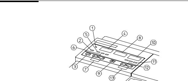
Figure 1-1 General Layout of the Series 50 A and Series 50 IP-2 Fetal
Monitors
Chapter 1 General Information |
5 |
Major Keys and Parts at a Glance
1.Mains socket
2.Monitor on/off switch
3.Equipotential grounding point
4.Monitor on/off light
5.Display panel
6.Time and date key
7.Paper speed key
8.Test key
9.Recorder on/off light
10.Recorder on/off key
11.Event marker key (Alert acknowledge key)
12.Paper advance key
13.Loudspeaker
14.Battery compartment
15.Paper table
16.Service socket
17.Series 50 A: US2 Socket (not present on Single Ultrasound model) Series 50 IP-2: US2/ECG Socket
18.Toco socket
19.Series 50 A: Single Ultrasound Model: US Socket
Double Ultrasound Model: US1 socket
Series 50 IP-2:US1 socket
20.Socket for remote event marker
21.Lock-release button
22.Combined interface module
23.Integrated carrying handle
24.Cable clamp
6 |
Chapter 1 General Information |
Monitor Control and Display Panel
Monitor Control and Display Panel
M1351A Single
Ultrasound
Model
Figure 1-2 Layout of the Monitor Control and Display Panel
1.Monitor On/Off Light.
2.Telemetry Indicator. On when the Fetal Telemetry Receiver is connected and switched on.
3.Function Key. Used to switch FMP and Fetal Alerting on and off.
4.US Display. Shows the FHR detected by the US transducer.
5.US Signal Quality Indicator. Indicates the quality of the signal detected by the US transducer:
"Green (optimum).
"Yellow (fair to potentially poor).
"Red (unacceptable).
6.US Speaker Light. On when you are hearing the US heartbeat.
7.US Volume Keys. Sets the volume and selects the US heartbeat.
8.Toco Display. Shows uterine activity.
9.Toco Baseline Key. Zeroes the Toco display and trace to 20 units.
M1351A Dual
Ultrasound
Twins Model
1.Monitor On/Off Light.
2.Telemetry Indicator. On when the Fetal Telemetry Receiver is connected and switched on.
3.Function Key. Used to switch Twins Offset, FMP, and Fetal Alerting on and off.
4.US1 Display. Shows the FHR detected by the US1 transducer.
Chapter 1 General Information |
7 |
Monitor Control and Display Panel
5.US1 Signal Quality Indicator. Indicates the quality of the signal detected by the US1 transducer.
6.US1 Speaker Light. On when you are hearing the US1 heartbeat.
7.US1 Volume Keys. Sets the volume and selects the US1 heartbeat.
8.Toco Display. Shows uterine activity.
9.Toco Baseline Key. Zeroes the Toco display and trace to 20 units.
10.US2 Display. Shows the FHR detected by the US2 transducer.
11.US2 Signal Quality Indicator. Indicates the quality of the signal detected by the US2 transducer.
12.US2 Speaker Light. On when you are hearing the US2 heartbeat.
13.US2 Volume Keys. Sets the volume and selects the US2 heartbeat.
M1353A Model 1. Monitor On/Off Light.
2.Telemetry Indicator. On when the Fetal Telemetry Receiver is connected and switched on.
3.Function Key. Used to switch Twins Offset, Logic, FMP, and Fetal Alerting on and off.
4.US Display. Shows the FHR detected by the US transducer.
5.US1 Signal Quality Indicator. Indicates the quality of the signal detected by the US1 transducer:
6.US1 Speaker Light. On when you are hearing the US1 heartbeat.
7.US1 Volume Keys. Sets the volume and selects the US1 heartbeat.
8.Toco Display. Shows uterine activity.
9.Toco Baseline Key. Zeroes the Toco display and trace to 20 units (when monitoring externally) or 0 units (when monitoring internally).
10.US2/ECG Display. Shows the FHR detected by the ECG transducer.
11.US2/ECG Signal Quality Indicator. Indicates the quality of the signal detected by the ECG transducer.
12.US2/ECG Speaker Light. On when you are hearing the ECG heartbeat.
13.US2/ECG Volume Keys. Sets the volume and selects the ECG heartbeat.
8 |
Chapter 1 General Information |
Accessories
Accessories
Series 50 A |
The following accessories are supplied as standard with the Monitor: |
||
(M1351A) |
! One external Toco transducer (M1355-60011). |
||
|
|||
|
! |
One ultrasound transducer (M1356-60011) (or two with the Dual Ultrasound |
|
|
|
Model). |
|
|
! |
Two reusable transducer belts (M1562A) (or three with Dual Ultrasound Model). |
|
|
! Three transducer knob adapters (M1356-43201). |
||
|
! |
One power cord. |
|
|
! |
One pack of paper: |
|
|
|
" |
M1910A (USA/Canada) |
|
|
" |
M1911A (Europe) |
|
|
" |
M1913A (Japan) |
|
! |
One bottle of gel: 40483A (Acquasonic gel) |
|
|
! |
One User’s Guide. |
|
|
! |
One Installation and Service Guide |
|
|
! |
One remote event marker (15249A). |
|
Series 50 IP-2 The following accessories are supplied as standard with the Monitor:
(M1353A)
!One external Toco transducer (M1355-60011).
!One ultrasound transducer (M1356-60011).
!One patient module M1364A with cables:
"One DECG legplate adapter cable (M1362B)
"One MECG adapter cable (M1363A)
!Five spiral electrodes:
"15133D Single spiral (USA).
"15133E Double spiral (Europe).
!Three reusable transducer belts.
!Three transducer knob adapters (M1356-43201).
!One power cord.
!Equipotential grounding cable:
Chapter 1 General Information |
9 |
Accessories
"
"
8120-2961 (USA).
8120-4808 (Europe).
!One pack of paper:
"
"
"
M1910A (USA/Canada)
M1911A (Europe)
M1913A (Japan)
!
!
!
One bottle of gel: 40483A (Acquasonic gel)
One Instructions for Use.
One Installation and Service Guide.
Documentation The following documentation is available for the Series 50 A and Series 50 IP-2 fetal monitors. Unless otherwise specified localized versions are available.
!Technical Data Sheets: Contain features and benefits, technical specifications, accessories, ordering, upgrading and re-ordering information.
!Service Documentation: All service documentation is in English.
!Instructions for Use: Detailed operating information, care and cleaning, and safety requirements.
!Video Tapes: 30-minute VHS video tapes demonstrating the Monitor.
!Barcode Booklets: Labels and cards, and instructions on how to customize sheets of nursing notes.
!Digital Interface Protocol Specifications: Written as a programmer's guide, describing the data exchange between the Series 50 Fetal Monitors and an Information Management System such as OB TraceVue. English only.
10 |
Chapter 1 General Information |
Accessories
Options |
The following accessories can also be supplied when the appropriate option is ordered. |
|||
|
|
|
||
Accessories |
Option |
Model |
||
|
|
|
||
Barcode Reader, including a reader and barcode booklet. This |
H15 |
Series 50 A and Series 50 IP |
||
requires Option J10 or J15. |
|
|
|
|
|
|
|
||
Combined Interface Module for telemetry and obstetrical |
J101 |
Series 50 A and Series 50 IP |
||
surveillance systems (e.g. Philips OB TraceVue) and barcode |
|
|
|
|
reader |
|
|
|
|
|
|
|
||
Combined Interface Module for telemetry and obstetrical |
J131 |
Series 50 A and Series 50 IP |
||
surveillance systems (e.g. Philips OB TraceVue), includes an |
|
|
|
|
interface cable M1350-61609. |
|
|
|
|
• for Dinamap 1846 or |
|
|
|
|
• COLIN Press-Mate/Nippon Colin Listmini Model BP- |
|
|
|
|
8800 NIBP Monitor |
|
|
|
|
|
|
|
||
Combined Interface Module for telemetry and obstetrical |
J141 |
Series 50 A and Series 50 IP |
||
surveillance systems (e.g. Philips OB TraceVue), includes an |
|
|
|
|
interface cable M1353-61614 |
|
|
|
|
• for Nellcor OxiFirst™ Fetal Oxygen Saturation Monitor |
|
|
|
|
(N-400) |
|
|
|
|
|
|
|
||
Modem Interface Module allows the transmission of fetal |
J151 |
Series 50 A |
||
trace data from a Series 50 A to a receiver (e.g., an OB |
|
|
|
|
TraceVue system) |
|
|
|
|
|
|
|
|
|
Fetal Movement Profile |
|
C02 |
|
Series 50 A and Series 50 IP |
|
|
|
|
|
IUP Pressure Transducer (CPJ840J5) |
C07 |
|
Series 50 IP |
|
|
|
|
|
|
Disposable IUP Catheter. This includes 1 x box M1333A |
C08 |
2 |
Series 50 IP |
|
(containing 10 catheters) disposable intrauterine sensor-tip |
|
|
||
|
|
|
||
pressure catheters and M1334A reusable connector cable |
|
|
|
|
|
|
|
|
|
1.Options J10, J13, J14 and J15 cannot be fitted at the same time
2.Not available in all countries.
Chapter 1 General Information |
11 |
Accessories
|
Accessories |
Option |
Model |
|
|
|
|
||
Service and Installation Guide |
0B3 |
Series 50 A and |
||
|
|
|
Series 50 IP |
|
|
|
|
||
Installation and Operating Guide Video |
0B5 |
Series 50 A and |
||
• |
VHS ⁄NTSC |
|
Series 50 IP |
|
• |
VHS ⁄PAL |
|
|
|
|
|
|
||
Wall mounting kit |
1AB |
Series 50 A and |
||
|
|
|
Series 50 IP |
|
|
|
|
||
Paper take-up tray1 |
1AC |
Series 50 A and |
||
|
|
|
Series 50 IP |
|
|
|
|
|
|
Angled mounting kit |
1AD |
Series 50 |
A and |
|
|
|
|
Series 50 |
IP |
|
|
|
|
|
Mobile cart |
2AE |
Series 50 |
A and |
|
|
|
|
Series 50 |
IP |
|
|
|
|
|
1. Not compatible with the wall mounting kit.
12 |
Chapter 1 General Information |

2
Technical Specifications
Monitor
Power
Requirements
The monitor is set for the correct voltage at the factory. Before you connect power, however, ensure that the voltage label shows the correct setting for your country.
Operating Voltage: |
100V - 120V or 220V - 240V (±10%). |
Line Frequency: |
50 to 60Hz ±5%. |
Power Consumption: |
25VA max. |
Battery Type: |
2 x 1.5V (AA size). Lifetime > 1 year. |
Environment |
The monitor should be used in an environment which is reasonably free from vibration, |
|
|
dust, corrosive or explosive gases, extremes of temperature, humidity, etc. It operates within |
|
|
specifications at ambient temperatures between 0 and 55°C. Ambient temperatures which |
|
|
exceed these limits can affect the accuracy of the monitor and cause damage to the |
|
|
components and circuits. Allow at least 5cm (2in) clearance around the monitor for proper |
|
|
air circulation. |
|
|
Operating Temp: |
0 to +55°C (32°F to 131°F). |
|
Storage Temp: |
-40 to +75°C (-40°F to 167°F), excludes transducers: -40 to |
|
|
+60°C (-40°F to +140°F) |
|
Relative Humidity: |
5 to 95%. |
Weight and |
Height: |
115mm (4.5in). |
Dimensions |
Width: |
340mm (13.4in). |
|
||
|
Depth: |
308mm (12.1in). |
|
Weight: |
5.74kg (12.6lb) (without transducers). |
Chapter 2 Technical Specifications |
13 |
Monitor
Displays
Numerical Display M1351A Single
Ultrasound Model: One heart rate display (orange) and one uterine activity display (green).
M1351A Dual
Ultrasound Twins Model: Two heart rate displays and one uterine activity display.
M1353A Model: |
Two heart rate displays and one uterine activity display. |
Type: |
7-segment LEDs (10mm). |
FHR Range: |
50 to 240 bpm. |
Uterine Activity Range: |
-99 to +127 relative units. |
Instrument Display Telemetry Mode is displayed if Option J10 is fitted and an M2720A Avalon CTS Cordless Fetal Transducer System or M1310A or 80240A Fetal Telemetry System is connected and switched on.
M1351A Single
Ultrasound Model: One signal quality indicator.
M1351A Dual
Ultrasound Twins Model: Two signal quality indicators.
M1353A Model: Two signal quality indicators.
Inputs |
M1351A Single |
|
|
Ultrasound Model |
US socket accepts the M1356A ultrasound transducer. Toco |
|
|
socket accepts the M1355A Toco transducer. Socket for the |
|
|
Remote Event Marker (15249A), and another for servicing. The |
|
|
monitor automatically selects the correct operating mode. |
|
M1351A Dual |
|
|
Ultrasound Twins Model US1 and US2 sockets accept M1356A ultrasound transducers. |
|
|
|
Toco socket accepts the M1355A Toco transducer. Socket for the |
|
|
Remote Event Marker (15249A), and another for servicing. The |
|
|
monitor automatically selects the correct operating mode. |
|
M1353A Model |
US1 socket accepts the M1356A ultrasound transducer. Toco |
|
|
socket accepts the M1355A external Toco or the M1350A/ |
8040A compatible internal Toco transducer. US2/ECG socket accepts either the M1356A ultrasound transducer, or the M1364A DECG/MECG patient module or the M1357A DECG or the M1359A MECG transducer. There is a socket for the remote event marker (15249A), and another for servicing. The monitor automatically selects the correct operating mode.
14 |
Chapter 2 Technical Specifications |
Monitor
Ultrasound Mode |
System: |
Pulsed Doppler oscillation. |
|
Frequency: |
998.4 kHz. |
|
Repetition Rate: |
3.2 kHz. |
|
Ultrasound Intensity: |
1.5mW/cm² average for each of the seven active surfaces. |
DECG and MECG See Specifications for Transducers and Cables on page 17. |
||
Mode |
|
|
External Labor |
Signal Range: |
0 to 127 units. |
|
Offset Compensation: |
±200 units. |
Internal Labor |
Signal Range: |
-99 to +127 mmHg. |
|
Patient Leakage Current: |
≤ 10 µArms. |
|
Sensitivity: |
40 µV/V/mmHg (M1348A). |
|
|
5 µV/V/mmHg (M1334A and CPJ840J5). |
Recorder |
Mechanism: |
3-channel, high-resolution (8 dots/mm) thermal array recorder |
|
|
with paper-end detection. |
|
Paper Speeds: |
1, 2 or 3 cm/min. |
|
Recording Time Per Pack |
|
|
of Paper: |
1 cm/min (25 h). |
|
|
2 cm/min (12 h 30 min). |
|
|
3 cm/min (8 h 20 min). |
|
Paper Advance Speed: |
24 cm/min (with automatic stop at the paper-end mark). |
|
Annotation: |
Time of day, date, and paper speed are printed automatically |
|
|
every ten minutes. Monitoring mode is printed with every |
|
|
alteration of parameter. |
|
Paper: |
Fanfold paper with numbered pages. |
|
FHR Scale: |
USA: 30 to 240 bpm @ 30 bpm/cm. |
|
|
Other countries: 50 to 210 bpm @ 20 bpm/cm. |
|
Labor Scale: |
0 to 100 units @ 25 units/cm. |
Chapter 2 Technical Specifications |
15 |
Monitor
Self-Test
Facilities
Combined
Interface
Module
Self-test facilities include:
System test: |
With no transducers connected (includes a display and recorder |
|
test). |
Parameter test: |
With the appropriate transducer connected, the monitoring |
|
mode (ultrasound or uterine activity) is tested. |
Telemetry: |
M1310A Fetal Telemetry System. |
System: |
M1383A/B/C OB TraceVue. |
Either |
|
Barcode Reader: |
SmartWand. |
or
Maternal NIBP Monitor: Dinamap 1846/8100.
COLIN Press-Mate /Nippon Colin Listmini Model BP-8800. or
Nellcor OxiFirst Fetal Oxygen Saturation Monitor (N-400) or compatible.
Modem |
Modem: |
Interface socket for an Philips-approved PCMCIA card modem. |
|
Interface |
Fetal Trace Memory: |
Local fetal trace storage. |
|
Module |
|||
Barcode Reader: |
|
||
|
Smart Wand. |
||
|
RS232 Serial Interface: |
For internal use only. |
|
Remote Event |
Length: |
2.8m/9ft 2in. |
|
Marker |
Weight: |
75g/2.65oz. |
|
(15249A) |
|||
|
|
16 |
Chapter 2 Technical Specifications |

Transducers and Cables
Transducers and Cables
|
Transducers can be stored at temperatures between -40 and +60°C. |
||
Brown Toco |
System: |
Passive Straingauge. |
|
Transducer |
Dynamic Range: |
0 to 12N (overload protected). |
|
(M1355A) |
|||
Weight: |
180g/6.3oz. |
||
|
|||
|
Cable Length: |
2.5m/8ft 2in. |
|
Blue1 Toco |
System: |
Passive Straingauge. |
|
Transducer |
Dynamic Range: |
0 to 12N (overload protected). |
|
(M1355A) |
|||
Weight: |
|
||
|
180g/6.3oz. |
||
|
Cable Length: |
2.5m/8ft 2in or 0.7m/2ft 3in. |
|
Brown |
System: |
Pulsed Doppler. |
|
Ultrasound |
Oscillator Frequency: |
998.4kHz. |
|
Transducer |
|||
|
|
||
(M1356A) |
Weight: |
185g/6.5oz. |
|
|
Cable Length: |
+ 2.5m/8ft 2in. |
|
|
Size: |
75mm/2.95in diameter. |
|
Blue1 |
System: |
Pulsed Doppler. |
|
Ultrasound |
Oscillator Frequency: |
998.4kHz. |
|
Transducer |
|||
|
|
||
(M1356A) |
Weight: |
185g/6.5oz. |
|
|
Cable Length: |
2.5m/8ft 2in or 0.7m/2ft 3in. |
|
|
Size: |
75mm/2.95in diameter. |
|
1. Indicates transducer is waterproof.
Chapter 2 Technical Specifications |
17 |
Transducers and Cables
DECG Transducer (M1357A)
MECG Transducer (M1359A)
DECG/MECG Patient Module (M1364A)
Input Impedance: |
>10MΩ (differential, dc to 50/60Hz). |
|
CMRR: |
>110dB (with patient cable, 51.5kΩ |
/0.047µF imbalance at line |
|
frequency). |
|
Noise: |
<4µVp (referred to input with 25kΩ |
). |
Contact Potential |
|
|
Tolerance: |
±400mV. |
|
Input Voltage Range: |
20µVp to 3mVp. |
|
Patient Leakage Current: <10µArms @ 120V/60Hz. |
|
|
Patient Auxiliary Current:<0.1µA (dc). |
|
|
Dielectric Strength: |
1500Vrms (spark-gap protected). |
|
Weight: |
185g/6.5oz. |
|
Cable Length: |
2.5m/8ft 2in or 0.7m/2ft 3in. |
|
Input Impedance: |
>10MΩ (differential, dc to 50/60Hz). |
|
CMRR: |
>90dB (with patient cable, 51.5kΩ |
/0.047µF imbalance at line |
|
frequency). |
|
Noise: |
<4µVp (referred to input with 25kΩ |
). |
Contact Potential |
|
|
Tolerance: |
±400mV. |
|
Input Voltage Range: |
80µVp to 4mVp. |
|
Patient Leakage Current: <10µArms @ 120V/60Hz. |
|
|
Patient Auxiliary Current:<0.1µA (dc). |
|
|
Dielectric Strength: |
1500Vrms (spark-gap protected). |
|
Weight: |
175g/6.2oz. |
|
Cable Length: |
2.5m/8ft 2in. |
|
The patient module has a 7-pin ECG connector into which you can plug either DECG cable (M1362A or B) or MECG cable (M1363A).
Overall length: 2706mm (+30, -100mm)
Length of free cable: 2618mm (+30, -100mm)
Weight: 120 grams
Size: 88x42x30mm
Socket: DECG or MECG connection
18 |
Chapter 2 Technical Specifications |
Loading...