


DVD Micro System |
MCD190 |
|
all versions |
ServiceManual
TABLE OF CONTENTS
Handling chip components ............................................................ |
1-1 |
Information about lead-free soldering............................................ |
1-2 |
Technical specification................................................................... |
2-1 |
Service tools .................................................................................. |
2-1 |
Service measurement setup.......................................................... |
2-2 |
Connections and controls...................................................... |
3-1...3-4 |
Disassembly diagram .................................................................... |
4-1 |
Service test program...................................................................... |
5-1 |
Set block diagram.......................................................................... |
5-2 |
Set wiring diagram......................................................................... |
5-3 |
DISPLAY BOARD |
|
circuit diagram .......................................................................... |
6-1 |
layout diagram .......................................................................... |
6-2 |
|
|
|
|
|
|
|
|
|
|
|
|
|
|
|
|
|
|
|
|
|
|
|
|
|
|
|
|
|
|
|
|
|
|
|
|
|
|
|
|
|
|
|
|
|
|
|
|
|
|
|
|
|
|
|
|
|
|
|
|
|
|
|
|
|
|
|
|
|
|
|
|
|
|
|
|
|
|
|
|
|
|
|
|
|
|
|
CASSETTE BOARD |
|
|
|
|
|
|
|
|
|
|
|
|
|
|
|
|
||||||||||||
|
|
|
|
circuit diagram .......................................................................... |
|
|
|
|
|
|
|
|
|
|
|
|
|
7-1 |
||||||||||
|
|
|
|
layout diagram .......................................................................... |
|
|
|
|
|
|
|
|
|
|
|
|
|
7-2 |
||||||||||
MAIN BOARD |
|
|
|
|
|
|
|
|
|
|
|
|
|
|
|
|
||||||||||||
|
|
|
|
circuit diagram .................................................................. |
8-1 |
...8-2 |
||||||||||||||||||||||
|
|
|
|
layout diagram.................................................................. |
8-3... |
8-4 |
||||||||||||||||||||||
MPEG BOARD |
|
|
|
|
|
|
|
|
|
|
|
|
|
|
|
|
||||||||||||
|
|
|
|
circuit diagram .................................................................. |
9-1... |
9-3 |
||||||||||||||||||||||
|
|
|
|
layout diagram .......................................................................... |
|
|
|
|
|
|
|
|
|
|
|
|
|
9-4 |
||||||||||
Exploded view diagram................................................................ |
|
|
|
|
|
|
|
|
|
|
|
|
|
10-1 |
||||||||||||||
Mechanical partslist ..................................................................... |
|
|
|
|
|
|
|
|
|
|
|
|
|
10-2 |
||||||||||||||
Electrical partslist............................................................... |
11-1...11-2 |
|||||||||||||||||||||||||||
Revision list.................................................................................. |
|
|
|
|
|
|
|
|
|
|
|
|
|
12-1 |
||||||||||||||
© Copyright 2005 Philips Consumer Electronics B.V. Eindhoven, The Netherlands
All rights reserved. No part of this publication may be reproduced, stored in a retrieval system or transmitted, in any form or by any means, electronic, mechanical, photocopying, or otherwise without the prior permission of Philips.
Published by LX 0551 Service Audio Printed in The Netherlands Subject to modification
CLASS 1
LASER PRODUCT
© 3141 785 30532
Version 1.2

1 - 1
HANDLING CHIP COMPONENTS
HANDLING CHIP COMPONENTS
© WARNING
All ICs and many other semiconductors are susceptible to electrostatic discharges (ESD). Careless handling during repair can reduce life drastically.
When repairing, make sure that you are connected with the same potential as the mass of the set via a wristband with resistance. Keep components and tools at this potential.
f ATTENTION
Tous les IC et beaucoup d´autres semi-conducteurs sont sensibles aux décharges statiques (ESD). Leur longévite pourrait être considérablement écourtée par le fait qu´aucune précaution nést prise à leur manipulation.
Lors de réparations, s´assurer de bien être relié au même potentiel que la masse de l´appareil et enfileer le bracelet serti d´une résistance de sécurité.
Veiller à ce que les composants ainsi que les outils que l´on utilise soient également à ce potentiel.
ESD
d WARNUNG
Alle ICs und viele andere Halbleiter sind empfindlich gegenüber elektrostatischen Entladungen (ESD). Unsorgfältige Behandlung im Reparaturfall kann die Lebensdauer drastisch reduzieren.
Sorgen Sie dafür, daß Sie im Reparaturfall über ein Pulsarmband mit Widerstand mit dem Massepotential des Gerätes verbunden sind.
Halten Sie Bauteile und Hilfsmittel ebenfalls auf diesem Potential.
ñ WAARSCHUWING
Alle IC´s en vele andere halfgeleiders zijn gevoelig voor electrostatische ontladingen (ESD).
Onzorgvuldig behandelen tijdens reparatie kan de levensduur drastisch doen vermindern. Zorg ervoor dat u tijdens reparatie via een polsband met weerstand verbonden bent met hetzelfde potentiaal als de massa van het apparaat.
Houd componenten en hulpmiddelen ook op ditzelfde potentiaal.
i AVVERTIMENTO
Tutti IC e parecchi semi-conduttori sono sensibili alle scariche statiche (ESD).
La loro longevità potrebbe essere fortemente ridatta in caso di non osservazione della più grande cauzione alla loro manipolazione. Durante le riparationi occorre quindi essere collegato allo stesso potenziale che quello della massa delápparecchio tramite un braccialetto a resistenza. Assicurarsi che i componenti e anche gli utensili con quali si lavora siano anche a questo potenziale.
©
Safety regulations require that the set be restored to its original condition and that parts which are identical with those specified be used.
Safety components are marked by the symbol 
f
Les normes de sécurité exigent que l`appareil soit remis à l`état d`origine et que soient utilisées les pièces de rechange identiques à celles spécifiées.
Les composants de sécurité sont marqués 
©DANGER: Invisible laser radiation when open. AVOID DIRECT EXPOSURE TO BEAM.
s Varning !
Osynlig laserstrålning när apparaten är öppnad och spärren är urkopplad. Betrakta ej strålen.
∂ Advarsel !
SAFETY
d
Bei jeder Reparatur sind die geltenden Sicherheitsvorschriften zu beachten. Der Originalzustand des Gerätes darf nicht verändert werden. Für Reparaturen sind Originalersatzteile zu verwenden.
Sicherheitsbauteile sind durch das Symbol  markiert.
ñ
Veiligheidsbepalingen vereisen, dat het apparaat in zijn oorspronkeliijke toestand wordt teruggebracht en dat onderdelen, identiek aan de gespecificeerde, worden toegepast. De Veiligheidsonderdelen zijn aangeduid met het symbool 
i
Le norme di sicurezza estigono che l´apparecchio venga rimesso nelle condizioni originali e che siano utilizzati i pezzi di ricambiago identici a quelli specificati. Componenty di sicurezza sono marcati con
|
CLASS 1 |
© |
|
LASER PRODUCT |
After servicing and before returning the set to customer |
|
perform a leakage current measurement test from all |
|
|
|
exposed metal parts to earth ground, to assure no |
|
|
shock hazard exists. |
|
|
|
|
|
The leakage current must not exceed 0.5mA. |
ß Varoitus ! |
f |
|
Usynlig laserstråling ved åbning når sikkerhedsafbrydere er ude af funktion. Undgå udsaettelse for stråling.
Avatussa laitteessa ja suojalukituksen ohitettaessa olet alttiina näkymättömälle laserisäteilylle. Älä katso säteeseen !
"Pour votre sécurite, ces documents doivent être utilisés par des spécialistes agréés, seuls habilités à réparer votre appareil en panne".

1 - 2
INFORMATION ABOUT LEAD-FREE SOLDERING
Philips CE is producing lead-free sets from 1.1.2005 onwards.
IDENTIFICATION:
Regardless of special logo (not always indicated) one must treat all sets from 1 Jan 2005 onwards, according next rules:
Example S/N:
Bottom line of typeplate gives a 14-digit S/N. Digit 5&6 is the year, digit 7&8 is the week number, so in this case 2005 wk12
So from 0501 onwards = from 1 Jan 2005 onwards
Im portant note : In fact also products of year 2004 must be treated in this way as long as you avoid mixin g solder-alloys ( leaded/lead -free). So best to always use SAC305 and the higher temperatures belon g t o this.
Due to lead-free technology some rules have to be respected by the workshop during a repair:
•Use only lead-free solder alloy Philips SAC305 with order code 0622 149 00106. If lead-free solder-paste is required, please contact the manufacturer of your solder-equipment. In general use of solder-paste within workshops should be avoided because paste is not easy to store and to handle.
•Use only adequate solder tools applicable for lead-free solder alloy. The solder tool must be able
o To reach at least a solder-temperature of 40

o To stabilize the adjusted temperature at the solder-tip
oTo exchange solder-tips for different applications.
•Adjust your solder tool so that a temperature around 

 −
− 

 is reached and stabilized at the solder joint. Heating-time of the solder-joint should not exceed ~ 4 sec. Avoid temperatures above 400
 otherwise wear-out of tips will rise drastically and flux-fluid will be destroyed. To avoid wear-out of tips switch off un-used equipment, or reduce heat.
•Mix of lead-free solder alloy / parts with leaded solder alloy / parts is possible but PHILIPS recommends strongly to avoid mixed solder alloy types (leaded and lead-free).
If one cannot avoid or does not know whether product is lead-free, clean carefully the solder-joint from old solder alloy and re-solder with new solder alloy (SAC305).
•Use only original spare-parts listed in the Service-Manuals. Not listed standard-material (commodities) has to be purchased at external companies.
•Special information for BGA-ICs:
-always use the 12nc-recognizable soldering temperature profile of the specific BGA (for de-soldering always use the lead-free temperature profile, in case of doubt)
-lead free BGA-ICs will be delivered in so-called 'dry-packaging' (sealed pack including a silica gel pack) to protect the IC against moisture. After opening, dependent of MSL-level seen on indicator-label in the bag, the BGA-IC possibly still has to be baked dry. (MSL=Moisture Sensitivity Level). This will be communicated via AYS-website.
Do not re-use BGAs at all.
•For sets produced before 1.1.2005 (except products of 2004), containing leaded solder-alloy and components, all needed spare-parts will be available till the end of the service-period. For repair of such sets nothing changes.
•On our website www.atyourservice.ce.Philips.com you find more information to:
BGA-de-/soldering (+ baking instructions)
Heating-profiles of BGAs and other ICs used in Philips-sets
You will find this and more technical information within the "magazine", chapter "workshop news".
For additional questions please contact your local repair-helpdesk.
SERVICE INSTRUCTION
Safety regulations require that after a repair, the set must be returned in its original condition. Pay in particular attention to the following points:
·Route the wire trees correctly and fix them with the mounted cable clamps.
·Check the insulation of the AC Power lead for external damage.
·Check the strain relief of the AC Power cord for proper function.
·Check the electrical DC resistance between the AC Power Plug and the secondary side (only for sets which have a AC Power isolated power supply):
1.Unplug the AC Power cord and connect a wire between the two pins of the AC Power plug.
2.Set the AC Power switch to the "on" position (keep the AC Power cord unplugged!).
3.Measure the resistance value between the pins of the AC Power plug and the metal shielding of the tuner or the aerial connection on the set. The reading should be larger than 4.5 Mohm (For U.S. it should be between 4.2 Mohm and 12 Mohm).
4.Switch "off" the set, and remove the wire between the two pins of the AC Power plug.
•Check the cabinet for defects, to avoid touching of any inner parts by the customer.
-/98 : 120 / 230 V -/79 : 240 V
-/93 : 220V
-/96 : 120 / 230 V
-/98 : 50 / 60 Hz -/79 : 50 Hz -/93 : 50 Hz -/96 : 50 / 60 Hz
remote : 1.5 V (AA x 2) normal : < 25 W
Standby : < 4 W
:141 x 233 x 212 mm
:2.9 Kg
mains : 2 x 4 W
:2 x 4 ohm
:63 Hz - 16 kHz (±3dB)
:87.5 - 108 MHz
:10.7 MHz ± 0.02 MHz
:< 22 dBf at 26dB 300kHz : > 33 dB
:> 60 dB
:> 25dB
:< 3 %
:>28dB
:100KHz
2 - 1
TUNER - AM SECTION
Tuning range |
9kHz |
: |
531 - 1602 kHz |
|
10kHz |
|
520 - 1710 kHz for /55 |
IF frequency |
|
|
450 kHz ± 1 kHz |
Sensitivity |
|
: ≤ 3.25 mV/m at 26dB |
|
Selectivity S9/300kHz |
|
: |
> 20 dB |
IF rejection |
|
: |
> 24 dB |
Distortion |
|
: |
< 5% |
Image rejection |
|
: |
> 28 dB |
AUDIO CASSETTE RECORDER
Speed Control |
: |
Nom ±1.5% |
Wow & flutter |
: |
< 0.4 % (DIN) |
Tape speed |
: |
4.76 cm/s |
Fast wind/rewind C60 |
: |
< 39 dB |
No of Tacks |
: |
2 Tacks (stereo) |
Recording Level |
: |
Auto |
DVD PLAYER
Frequency response |
: 4 Hz – 20 kHz(44.1KHz) |
|
|
|
4 Hz – 22 kHz(48KHz) |
|
|
4 Hz – 44 kHz(96KHz) |
Video S/N |
: |
56 dB(min) |
Video decording |
: |
MPEG-2/MPEG-1 |
Channel Separation |
1kHz : |
40 dB |
Video DAC |
: |
10bits |
VIDEO PERFORMANCE
Video Format |
: |
4:3/16:9 |
Disc Diameter |
: |
12cm/8cm |
Number of programmable tracks : |
16 |
|
Channel sepatation |
: |
≥ 40dB (1KHz) |
Signal to noise ratio |
: |
≥ 65dBA |
4822 466 10953
4822 466 10958
4822 395 10223
4822 320 11307
4822 320 11305
4822 320 11306
4822 320 11308
4822 310 10671
4822 344 13999
2 - 2
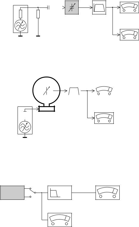
SERVICE MEASUREMENT
Tuner SW |
DUT |
Bandpass |
LF Voltmeter |
|
250Hz-15kHz |
||
RF Generator |
Aerial replacement |
e.g. 7122 707 48001 |
e.g. PM2534 |
Capacitor |
|
|
|
e.g. PM5326 |
|
|
|
Ri=50Ω |
R=50Ω |
|
|
|
|
|
S/N and distortion meter |
|
|
|
e.g. Sound Technology ST1700B |
To avoid atmospheric interference all AM-measurements have to be carried out in a Faraday«s cage. Use a bandpass filter (or at least a high pass filter with 250Hz) to eliminate hum (50Hz, 100Hz).
Tuner AM (MW,LW)
RF Generator
e.g. PM5326
Ri=50Ω
|
|
|
Bandpass |
LF Voltmeter |
||||
DUT |
250Hz-15kHz |
|||||||
e.g. 7122 707 48001 |
e.g. PM2534 |
|||||||
|
|
|
||||||
|
|
|
|
|
|
|
|
|
|
|
|
|
|
|
|
|
|
|
|
|
|
|
|
|
|
|
|
|
|
|
|
|
|
|
|
|
|
|
|
|
|
|
|
|
|
|
|
|
|
|
|
|
|
S/N and distortion meter e.g. Sound Technology ST1700B
Frame aerial e.g. 7122 707 89001
To avoid atmospheric interference all AM-measurements have to be carried out in a Faraday«s cage.
CD
Use Audio Signal Disc SBC429 4822 397 30184 (replaces test disc 3)
L.P.F. = 13 th order filter 4822 395 30204
DUT |
Low pass filter 22kHz |
L
R
S/N and distortion meter e.g. Sound Technology ST1700B
LEVEL METER
e.g. Sennheiser UPM550 with FF-filter

#
1 |
5 |
4 |
3 |
DISPLAY/ST |
6
1
4
$ |
|
|
|
|
|
2 |
|
|
6 |
|
|
|
|
# |
|
|
5 |
|
|
2 |
8 |
9 |
|
7 |
7 |
7 |
|
|
|
8 |
|
|
0 |
0 |
|
9 |
@ |
||
|
|||
8 |
! |
ª |
|
|
£ |
||
|
|
||
@ |
$ |
3 |
|
|
∞ |
• |
|
! |
% |
™ |
|
0 |
§ |
|
|
^ |
¡ |
||
|
|||
|
& |
) |
|
|
|
( |
|
|
|
* |
CONTROLS AND CONNECTION
1 - 3
%

Controls
Controls on the system
1 STANDBY ON y
–switches the system to standby/on.
2 iR sensor
–infrared sensor for remote control.
3CLOCK
Standby mode
*– sets the system clock. Playback mode
–displays the system clock.
4 PROGRAM
–DVD/VCD/CD/MP3-CD: enters the program menu.
–Picture CD: during playback, to select a slide show mode.
–Tuner: programs preset radio stations.
5 DISPLAY/ST
–Disc: to select disc information display mode.
–FM: to set stereo or mono sound mode.
6 Mode Selection
STOP 9 ............ In DISC mode, to stop playback or clear a program.
PLAY/PAUSE 2;
................................. In DISC mode, to start or interrupt playback.
PRESET 3 /4
Disc: skips to the previous/next chapter/title/ track.
Tuner: selects a preset radio station.
TUNING 22/33
Tuner
–press to tune to a lower/higher radio frequency gradually.
–press and hold, then release the key to start automatic search for a radio frequency downward/upward.
Disc
–searches fast backward/forward in a disc.
7 Display screen
–to view the current status of the system.
8 SOURCE
–to select the respective sound source : DISC TUNER, TAPE or AUX.
9 LOUDNESS
–enables or disables automatic loudness
adjustment.
0 DBB
–enables or disables bass enhancement.
! DSC
–selects different types of preset sound equalizer settings (CLASSIC, JAZZ, POP or ROCK).
@ VOLUME
–adjusts the volume upward/downward.
–adjusts the hours and minutes in clock/timer setting mode.
–in timer setting mode, switches the set timer ON or OFF.
# n
– to connect a headphone.
$ OPEN•CLOSE |
2 |
|
–to open or close the disc door.
%Tape Deck Operation RECORD ... starts recording. PLAY 2 ............ starts playback.
SEARCH 22 / 22 fast rewinds/winds the tape.
STOP•OPEN 9 0
................................. stops tape playback/recording; opens the tape compartment.
PAUSE ; ....... interrupts recording or playback.
Controls on the remote control
1 y
–switches the system on/off.
2 Numeric Keypad (0-9)
–inputs a track/title/chapter number of the disc.
–inputs the number of a preset radio station.
3 PROGRAM
–DVD/VCD/CD/MP3-CD: enters the program menu.
–Picture CD: during playback, to select a slide show mode.
–Tuner: programs preset radio stations.
4 SOURCE
–to select the respective sound source : DISC TUNER, TAPE or AUX.
5 SYSTEM MENU (disc mode only)
–to enter or exit the system menu bar.
6 DISC MENU (disc mode only)
–to start playback at any chosen time on the disc (for VCD operation with PBC off).
7 22/33
Tuner
–press to tune to a lower/higher radio frequency gradually.
–press and hold, then release the key to start automatic search for a radio frequency downward/upward.
Disc
–searches backward/forward in a disc at different speeds.
8 3/4
–In DISC mode, to select a movement direction in the disc menu or system menu bar.
9 OK
–to exit or confirm the selection.
0 |
|
3 /4 |
|
|
|
||
|
|
–Disc: skips to the previous/next chapter/title/ track.
–Tuner: selects a preset radio station.
! STOP 9
–In DISC mode, to stop playback or clear a program.
@ PLAY/PAUSE 2;
–In DISC mode, to start or interrupt playback.
# VOL +/-
–adjusts the volume upward/downward.
–adjusts the hours and minutes in clock/timer setting mode.
–switches the set timer ON or OFF.
$ REPEAT
–to repeat a track/disc.
% SUBTITLE
–selects a subtitle language.
^ SLEEP
–to set the sleep (auto-off) timer function.
& LOUDNESS
–enables or disables automatic loudness adjustment.
* DSC
– selects different types of preset sound equalizer settings (CLASSIC, JAZZ, POP or ROCK).
Controls
( DBB
–enables or disables bass enhancement.
) MUTE
–to interrupt or resume sound reproduction.
¡ DISPLAY (OSD)
–displays information on TV screen during playback.
–FM: to set stereo or mono sound mode.
™ SLOW
–selects different slow playback modes for a VCD/ SVCD/DVD.
£ SHUFFLE
–to repeat playback of all tracks in a random order.
 REPEAT A-B
–for CD: to repeat a specific section within the same track.
–for DVD/VCD: to repeat a specific section in a disc.
 AUDIO for VCD
–sets Stereo, Mono-Left or Mono-Right sound mode.
for DVD
–selects an audio language.
§ TIMER
*– to set the timer.
 ZOOM
ZOOM
–DVD/VCD/Picture CD: enlarges or reduces a picture or active image on the TV screen.
• ANGLE
–selects a DVD camera angle.
ª GOTO
–In DISC mode, to fast search in a disc by entering a time, title, chapter or track.
Notes for remote control:
–First, select the source you wish to control by pressing one of the source select keys on the remote control (VCD/ CD or TUNER, for example).
–Then select the desired function ( 2; 3 4 for example).
CONTROLS AND CONNECTION
2 - 3
* = Press and hold the button for more than three seconds. |
|
* = Press and hold the button for more than three seconds. |
|
|
|

Connections |
|
|
|
|
|
|
MW loop |
|
|
|
antenna |
FM wire antenna |
|
|
|
|
|
AM AERIAL |
|
|
|
FM AERIAL |
|
|
|
VIDEO OUT |
|
speaker |
|
S -V ID EO |
speaker |
|
o tu |
||
(right) |
COAXIAL |
Wof re |
(left) |
|
Su b- |
||
R |
L |
||
|
LINE OUT |
|
|
|
XUA |
|
|
|
NI |
|
|
|
R |
L |
|
|
|
|
AC power cord |
IMPORTANT!
-The type plate is located at the rear of the system.
-Before connecting the AC power cord to the wall outlet, ensure that all other connections have been made.
-Never make or change any connections with the power switched on.
To avoid overheating of the system, a safety circuit has been built in.Therefore, your system may switch to Standby mode automatically under extreme conditions. If this happens, let the system cool down before reusing it (not available for all versions).
Step 1: Placing speakers
Front |
Front |
speaker |
speaker |
( left ) |
( right ) |
VIEWING AREA
Place the front left and right speakers at equal distances from the TV set and at an angle of approximately 45 degrees from the listening position.
Notes:
-To avoid magnetic interference, do not position the front speakers too close to your TV set.
-Allow adequate ventilation around the DVD System.
Step 2: Connecting speakers
Connect the speaker wires to the SPEAKERS terminals, right speaker to "RIGHT" and left speaker to "LEFT", coloured (marked) wire to "+" and black (unmarked) wire to "-". Fully insert the stripped portion of the speaker wire into the terminal as shown.
Notes:
-Ensure that the speaker cables are correctly connected. Improper connections may damage the system due to short-circuit.
-For optimal sound performance, use the supplied speakers.
-Do not connect more than one speaker to any one pair of +/- speaker terminals.
-Do not connect speakers with an impedance lower than the speakers supplied. Please refer to the SPECIFICATIONS section of this manual.
Step 3: Antenna connection
MW Antenna
Connect the supplied MW loop antenna to the "MW AERIAL" terminal. Adjust the position of the antenna for optimal reception.
Position the antenna as far as possible from a TV, VCR or other radiation source.
Connections
FM Antenna
It is unnecessary to connect the FM pigtail antenna since it is fixed to the main unit. Adjust the FM antenna for optimal FM stereo reception.
Step 4: Connecting TV
IMPORTANT!
–You only need to make one video connection from the following options, depending on the capabilities of your TV system.
–Connect the DVD system directly to the TV.
Using Video In jack (CVBS)
|
AM AERIAL |
|
|
FM AERIAL |
|
|
VIDEO OUT |
|
|
S V- DI EO |
|
COAXIAL |
fe or u t |
|
ub-Woo |
||
|
||
|
S |
|
R |
L |
|
LINE OUT |
|
|
XUA |
|
|
NI |
|
|
R |
L |
Use the composite video cable (yellow) to connect the system's VIDEO jack to the video input jack (or labelled as A/V In,Video In, Composite or Baseband) on the TV set.
CONTROLS AND CONNECTION
3 - 3
Connections
Using S-Video In jack |
Using an accessory RF modulator |
IMPORTANT!
– If your TV set only has a single Antenna In jack (or labelled as 75 ohm or RF In), you will need a RF modulator in order to view the DVD playback via TV. See your electronics retailer or contact Philips for details on RF modulator availability and operations.
RF coaxial cable to TV
AM AERIAL |
|
|
|
FM AERIAL |
|
|
|
ANT IN |
TO TV VIDEO |
AUDIO IN |
|
VIDEO OUT |
IN |
R |
L |
|
S-VIDE O |
|
CH3 CH4 |
|
r uo t |
|
|
COAXIAL |
Wo fe |
|
|
|
Su b- |
|
|
R |
L |
|
|
LINE OUT |
|
Antenna or |
Back of RF Modulator |
|
|
||
|
|
Cable TV signal |
|
XUA |
|
(example only) |
|
|
|
||
NI |
|
|
|
R |
L |
|
|
Use the S-Video cable (not supplied) to connect the system's S-VIDEO jack to the S-Video input jack (or labelled as Y/C or S-VHS) on the TV set.
|
AM AERIAL |
|
|
FM AERIAL |
|
|
VIDEO OUT |
|
|
SVDI EO |
|
COAXIAL |
ef r out |
|
bWoo |
||
|
||
|
Su |
|
R |
L |
|
LINE OUT |
|
Use the composite cable (yellow) to connect the system's VIDEO jack to the video input jack on the RF modulator.
Use an RF coaxial cable (not supplied) to connect the RF modulator to your TV's RF jack.
Connections
Step 5: Connecting the power cord
IMPORTANT!
– Never make or change any connection with the power switched on.
After everything is connected properly, plug in the AC power cord to the power outlet.
Optional: Connecting additional equipment
IMPORTANT!
–Some discs are copy-protected.You cannot record the disc through a VCR or digital recording device.
–When making connections, make sure the colour of cables matches the colour of jacks.
–Always refer to the owner's manual of the other equipment for complete connection and usage details.
|
D |
C DIGITAL IN |
|
|
VIDEO IN |
AUDIO OUT |
AUDIO IN |
|
L |
R |
R B |
L |
|
A |
|
Viewing and listening to the playback of other equipment A
Connect the system's AUX IN (R/L) jacks to the AUDIO OUT jacks on the other audio/visual device (such as a TV, VCR, Laser Disc player or cassette deck).
Before starting operation, press SOURCE on the front panel to select AUX or press AUX on the remote in order to activate the input source.
Using the VCR for recording DVDs B
Connect one of the system's VIDEO OUT jacks to the corresponding VIDEO IN jack and LINE OUT (R/L) jacks to the AUDIO IN jacks on the VCR.This will allow you to make analogue stereo (two channel, right and left) recordings.
Recording (digital) C
Connect the system's COAXIAL jack to the DIGITAL IN jack on a digital recording device (such as DTS-Digital Theatre compatible, with Dolby Digital decoder).
Before starting operation, set the AUDIO OUT according to the audio connection. (See "DIGITAL OUT".)
Connecting an active subwoofer D
Connect the DVD micro system's SUBWOOFER OUT jack to the AUDIO INPUT jack on an active subwoofer (not supplied).
CONTROLS AND CONNECTION
4 - 3

DISASSEMBLY DIAGRAMS
ISASSEMBLY DIADRAMS
STEP A : Remove Rear Cabinet
-A1 : Remove 2 screws (SP3x12)
-A2 : Remove 4 screws (SP3x10)
-A3 : Remove 1 screws (SP3x10)
-A4 : Remove 2 screws (SP3x10)
A1
A6
4 - 1
-A5 : Remove 2 screws (SP3x10)
-A6 : Remove 2 screws (K3x10)
-A7 : Remove 2 screws (K3x10)
A2
A3
A4
A5
A7
STEP B : |
|
Remove Main board and LCD board |
|
- B1: Remove 2 screws (SP3x8) |
- B2: Remove 8 screws (SP2.5x8) |
B1
B2
 Loading...