


 Loading...
Philips MP20, MP60, MP40, MP30, MP50 User Manual
...
IntelliVue MP20/30, MP40/50 and MP60/70/80/90
INSTRUCTIONS FOR USE
IntelliVue Patient Monitor
MP20/30, MP40/50, MP60/70/80/90
Release D.0 with Software Revision D.00.xx
Patient Monitoring

Part Number M8000-9001G Printed in Germany 02/06 4512 610 13551
*M8000-9001G*

M8000-9001G
|
Table Of Contents |
|
|
1 Basic Operation |
1 |
|
|
|
Introducing the IntelliVue Family |
1 |
|
|
IntelliVue MP20/MP30 |
2 |
|
MP20/MP30 Major Parts and Keys |
3 |
|
IntelliVue MP40/MP50 |
4 |
|
MP40/MP50 Major Parts and Keys |
4 |
|
IntelliVue MP60/MP70 |
5 |
|
MP60/MP70 Major Parts and Keys |
6 |
|
IntelliVue MP80/MP90 |
6 |
|
MP80/MP90 Major Parts and Keys |
7 |
|
D80 Intelligent Display |
7 |
|
Remote Alarm Device |
7 |
|
Docking Station |
8 |
Related Products |
8 |
|
|
Flexible Module Server (M8048A) |
8 |
|
Measurement Modules |
9 |
|
Multi-Measurement Server (M3001A) |
10 |
|
Measurement Server Extensions |
11 |
|
M3014A, M3015A and M3016A Capnography Extensions |
12 |
|
M3012A Hemodynamic Measurement Server Extension |
13 |
Operating and Navigating |
14 |
|
|
Selecting Screen Elements |
15 |
|
Using the Setup Menu |
15 |
|
Using the Touchscreen |
15 |
|
Disabling Touchscreen Operation |
15 |
|
Using the SpeedPoint |
16 |
|
Using the Navigation Point |
17 |
|
Using a Mouse or Trackball |
17 |
|
Using Keys |
17 |
|
Permanent Keys |
17 |
|
SmartKeys |
18 |
|
Hardkeys |
19 |
|
Pop-Up Keys |
19 |
|
Using the On-Screen Keyboard |
20 |
|
Using the On-Screen Calculator |
20 |
Operating Modes |
21 |
|
|
Standby Mode |
21 |
Understanding Screens |
22 |
|
|
Switching to a Different Screen |
22 |
|
Changing a Screen’s Content |
22 |
Using Additional Displays |
23 |
|
|
Using the Visitor Screen |
24 |
i

Understanding Profiles |
24 |
|
|
Swapping a Complete Profile |
25 |
|
Swapping a Settings Block |
26 |
|
Default Profile |
26 |
|
Locked Profiles |
26 |
Understanding Settings |
26 |
|
|
Changing Measurement Settings |
26 |
|
Switching a Measurement On and Off |
27 |
|
Switching Numerics On and Off |
27 |
|
Adjusting a Measurement Wave |
27 |
Changing Wave Speeds |
27 |
|
|
Changing the Wave Group Speed |
27 |
|
Changing Wave Speed for a Channel |
28 |
Freezing Waves |
28 |
|
|
Freezing An Individual Wave |
28 |
|
Freezing All Waves |
28 |
|
Measuring Frozen Waves |
28 |
|
Changing The Wave Speed |
29 |
|
Updating The Frozen Wave |
29 |
|
Releasing Frozen Waves |
29 |
Using Labels |
29 |
|
|
About Label Sets |
29 |
|
Changing Measurement Labels (e.g. Pressure) |
29 |
|
Resolving Label Conflicts |
30 |
Changing Monitor Settings |
31 |
|
|
Adjusting the Screen Brightness |
31 |
|
Adjusting Touch Tone Volume |
31 |
|
Setting the Date and Time |
31 |
Checking Your Monitor Revision |
32 |
|
Getting Started |
32 |
|
|
Inspecting the Monitor |
32 |
|
Switching On |
32 |
|
Setting up the Measurement Servers and Modules |
32 |
|
Starting Monitoring |
33 |
Disconnecting from Power |
33 |
|
|
Monitoring After a Power Failure |
33 |
Networked Monitoring |
33 |
|
Using Remote Applications |
33 |
|
|
Remote Application Popup Keys |
34 |
|
2 What’s New? |
35 |
|
|
|
What’s New in Release D.0? |
35 |
|
What’s New in Release C.0? |
36 |
|
What’s New in Release B.1? |
37 |
|
What’s New in Release B.0? |
38 |
|
What’s New in Release A.2? |
39 |
|
ii

|
3 Alarms |
41 |
Visual Alarm Indicators |
42 |
|
Audible Alarm Indicators |
42 |
|
|
Alarm Tone Configuration |
42 |
|
Traditional Audible Alarms (HP/Agilent/Philips/Carenet) |
43 |
|
ISO/IEC Standard 9703-2 Audible Alarms |
43 |
|
Changing the Alarm Tone Volume |
43 |
|
Minimum Volume for No Central Monitoring INOP |
43 |
Acknowledging Alarms |
44 |
|
|
Acknowledging Disconnect INOPs |
44 |
|
Alarm Reminder (ReAlarm) |
44 |
Pausing or Switching Off Alarms |
44 |
|
|
To Pause All Alarms |
45 |
|
To Switch All Alarms Off |
45 |
|
To Switch Individual Measurement Alarms On or Off |
45 |
|
While Alarms are Paused or Off |
45 |
|
Restarting Paused Alarms |
46 |
|
Resetting Arrhythmia Alarm Timeouts |
46 |
|
Extending the Alarm Pause Time |
46 |
Alarm Limits |
46 |
|
|
Viewing Individual Alarm Limits |
46 |
|
Viewing All Alarm Limits |
47 |
|
Changing Alarm Limits |
48 |
|
About Automatic Alarm Limits (AutoLimits) |
49 |
|
Documenting Alarm Limits |
49 |
Reviewing Alarms |
50 |
|
|
Alarm Messages Window |
50 |
|
Review Alarms Window |
50 |
Understanding Alarm Messages |
51 |
|
Latching Alarms |
51 |
|
|
Viewing the Alarm Latching Settings |
51 |
|
Alarm Latching Behavior |
52 |
Testing Alarms |
52 |
|
Alarm Behavior at On/Off |
52 |
|
|
4 Patient Alarms and INOPs |
53 |
|
|
|
Patient Alarm Messages |
53 |
|
Technical Alarm Messages (INOPs) |
59 |
|
|
5 Managing Patients |
77 |
|
|
|
Admitting a Patient |
77 |
|
|
Patient Category and Paced Status |
78 |
|
Admitting a Centrally-Monitored Patient |
78 |
Quick Admitting a Patient |
78 |
|
Editing Patient Information |
79 |
|
iii

Discharging a Patient |
79 |
|
Transferring Patients |
80 |
|
|
Transferring a Centrally-Monitored Patient |
80 |
|
Transferring a Patient with an MMS (no Central Station) |
81 |
Data Upload from an MMS |
81 |
|
Data Exchange Between Information Centers |
82 |
|
Resolving Patient Information Mismatch |
82 |
|
|
Manually Resolving Patient Mismatch |
82 |
|
Patient Mismatch - If One Set of Patient Data is Correct |
83 |
|
Patient Mismatch - If Neither Patient Data Set is Correct |
83 |
|
Patient Mismatch - If Both Patient Data Sets Are Correct |
84 |
|
Automatically Resolving Patient Mismatch |
84 |
Care Groups |
84 |
|
|
Understanding the Care Group Overview Bar |
85 |
|
Viewing the My Care Group Window |
86 |
|
Viewing the Other Bed Window |
87 |
|
Other Bed Pop-Up Keys |
88 |
|
Visual Alarm Status Information in the Other Bed Window |
88 |
|
Care Group Alarms |
88 |
|
Telemetry Data Overview |
89 |
|
Unpairing a Telemetry Device |
89 |
|
Telemetry Data Overview Screen Element |
90 |
|
Silencing Telemetry Alarms from the Bedside |
90 |
|
Suspending Telemetry Alarms |
90 |
|
Using Standby |
90 |
|
6 ECG, Arrhythmia, and ST Monitoring |
91 |
|
|
|
Skin Preparation for Electrode Placement |
91 |
|
Connecting ECG Cables |
91 |
|
Selecting the Primary and Secondary ECG Leads |
92 |
|
Checking Paced Status |
92 |
|
Understanding the ECG Display |
93 |
|
Monitoring Paced Patients |
93 |
|
|
Setting the Paced Status (Pace Pulse Rejection) |
94 |
|
Avoiding Pace Pulse Repolarization Tails |
94 |
Changing the Size of the ECG Wave |
94 |
|
|
To Change the Size of an Individual ECG Wave |
94 |
|
To Change the Size of all the ECG Waves |
95 |
Changing the Volume of the QRS Tone |
95 |
|
Changing the ECG Filter Settings |
95 |
|
Choosing EASI or Standard Lead Placement |
96 |
|
About ECG Leads |
96 |
|
|
ECG Leads Monitored |
96 |
|
Changing Lead Sets |
96 |
ECG Lead Fallback |
97 |
|
ECG Lead Placements |
97 |
|
iv

Standard 3-Lead Placement |
98 |
Standard 5-Lead Placement |
98 |
Chest Electrode Placement |
99 |
10-Lead Placement |
100 |
Conventional 12-Lead ECG |
100 |
Modified 12-Lead ECG |
101 |
Choosing Standard or Modified Electrode Placement |
101 |
Labelling 12-Lead ECG Reports |
101 |
Capture 12-Lead |
102 |
EASI ECG Lead Placement |
102 |
ECG, Arrhythmia, and ST Alarm Overview |
104 |
Using ECG Alarms |
105 |
Extreme Alarm Limits |
105 |
ECG Alarms Off Disabled |
105 |
HR Alarms When Arrhythmia Analysis is Switched Off |
105 |
HR Alarms When Arrhythmia Analysis is Switched On |
105 |
ECG Safety Information |
105 |
About Arrhythmia Monitoring |
107 |
Arrhythmia Options |
107 |
Where Can I Find More Information? |
107 |
Switching Arrhythmia Analysis On and Off |
108 |
Choosing an ECG Lead for Arrhythmia Monitoring |
108 |
Aberrantly-Conducted Beats |
108 |
Atrial Fibrillation and Flutter |
108 |
Intermittent Bundle Branch Block |
109 |
Understanding the Arrhythmia Display |
109 |
Viewing Arrhythmia Waves |
109 |
Arrhythmia Beat Labels |
109 |
Arrhythmia Status Messages |
110 |
Rhythm Status Messages |
110 |
Ectopic Status Messages |
111 |
Arrhythmia Relearning |
111 |
Initiating Arrhythmia Relearning Manually |
111 |
Automatic Arrhythmia Relearn |
112 |
Arrhythmia Relearn and Lead Fallback |
112 |
Arrhythmia Alarms |
112 |
Yellow Arrhythmia Alarms |
113 |
Arrhythmia Alarms and Latching |
113 |
Switching Individual Arrhythmia Alarms On and Off |
113 |
Switching All Yellow Arrhythmia Alarms On or Off |
113 |
Adjusting the Arrhythmia Alarm Limits |
113 |
Arrhythmia Alarm Timeout Periods |
113 |
What is a Timeout Period? |
114 |
Resetting the Timeout Period |
114 |
How are Yellow Arrhythmia Alarms Indicated? |
114 |
Behavior of Unsilenced Arrhythmia Alarms |
114 |
v

|
Behavior of Silenced Arrhythmia Alarms |
114 |
|
|
Arrhythmia Alarm Chaining |
115 |
|
|
Understanding PVC-Related Alarms |
116 |
|
About ST Monitoring |
117 |
||
Switching ST On and Off |
117 |
||
|
Selecting ST Leads for Analysis |
117 |
|
Understanding the ST Display |
118 |
||
Updating ST Baseline Snippets |
119 |
||
Recording ST Segments |
119 |
||
About the ST Measurement Points |
120 |
||
|
Adjusting ST Measurement Points |
120 |
|
ST Alarms |
122 |
||
|
Singleor Multi-lead ST Alarming |
122 |
|
|
Changing ST Alarm Limits |
122 |
|
Viewing ST Maps |
122 |
||
|
Current View |
122 |
|
|
Trend View |
123 |
|
|
Viewing an ST Map |
124 |
|
|
Working in the ST Map Task Window |
124 |
|
|
Switching Between ST Map Views |
124 |
|
|
Displaying an ST Reference Baseline |
125 |
|
|
Updating an ST Map Reference Baseline |
125 |
|
|
Changing the Scale of the ST Map |
125 |
|
|
Changing the Trending Interval |
125 |
|
|
Printing an ST Map Report |
125 |
|
|
7 Monitoring Pulse Rate |
127 |
|
|
|
|
|
Entering the Setup Pulse Menu |
127 |
||
System Pulse Source |
127 |
||
Switching Pulse On and Off |
128 |
||
Using Pulse Alarms |
128 |
||
|
Selecting the Active Alarm Source: HR or Pulse? |
128 |
|
|
Alarm Source Selection Disabled |
129 |
|
|
Changing HR/Pulse Alarm Limits |
129 |
|
|
Extreme Alarm Limits |
129 |
|
|
QRS Tone |
129 |
|
|
8 Monitoring Respiration Rate (Resp) |
131 |
|
|
|
|
|
Lead Placement for Monitoring Resp |
131 |
||
|
Optimizing Lead Placement for Resp |
131 |
|
|
Cardiac Overlay |
131 |
|
|
Lateral Chest Expansion |
132 |
|
|
Abdominal Breathing |
132 |
|
Understanding the Resp Display |
132 |
||
Changing Resp Detection Modes |
132 |
||
|
Auto Detection Mode |
132 |
|
vi

Manual Detection Mode |
133 |
Resp Detection Modes and Cardiac Overlay |
133 |
Changing the Size of the Respiration Wave |
133 |
Changing the Speed of the Respiration Wave |
134 |
Using Resp Alarms |
134 |
Changing the Apnea Alarm Delay |
134 |
Resp Safety Information |
134 |
|
9 Monitoring SpO2 |
|
137 |
SpO2 Sensors |
137 |
||
Applying the Sensor |
137 |
||
Connecting SpO2 Cables |
138 |
||
Measuring SpO2 |
138 |
||
Assessing a Suspicious SpO2 Reading |
139 |
||
Understanding SpO2 Alarms |
140 |
||
|
Alarm Delays |
140 |
|
|
Adjusting the Alarm Limits |
140 |
|
|
Adjusting the Desat Limit Alarm |
140 |
|
Pleth Wave |
140 |
||
Perfusion (Pleth) Indicator |
141 |
||
Setting SpO2/Pleth as Pulse Source |
141 |
||
Setting Up Tone Modulation |
141 |
||
Setting the QRS Volume |
141 |
||
Calculating SpO2 Difference |
141 |
||
10 Monitoring NBP |
143 |
||
|
|
|
|
Introducing the Oscillometric NBP Measurement |
143 |
||
|
Measurement Limitations |
144 |
|
|
Measurement Methods |
144 |
|
|
Reference Method |
144 |
|
Preparing to Measure NBP |
144 |
||
|
Correcting the Measurement if Limb is not at Heart Level |
145 |
|
|
Understanding the NBP Numerics |
145 |
|
Starting and Stopping Measurements |
146 |
||
Enabling Automatic Mode and Setting Repetition Time |
146 |
||
Choosing the NBP Alarm Source |
147 |
||
Assisting Venous Puncture |
147 |
||
Calibrating NBP |
147 |
||
11 Monitoring Temperature |
149 |
||
|
|
|
|
Making a Temp Measurement |
149 |
||
|
Selecting a Temperature for Monitoring |
149 |
|
|
Extended Temperature Label Set |
150 |
|
Calculating Temp Difference |
150 |
||
vii

12 Monitoring Invasive Pressure |
151 |
||
|
|
|
|
Setting up the Pressure Measurement |
151 |
||
|
Selecting a Pressure for Monitoring |
152 |
|
|
Extended Pressure Label Set |
152 |
|
Zeroing the Pressure Transducer |
152 |
||
|
Zeroing ICP (or IC1/IC2) |
153 |
|
|
Determining a Pressure’s Most Recent Zero |
153 |
|
|
Zeroing a Pressure Measurement |
153 |
|
|
Using the Zero Hardkey |
153 |
|
|
Zeroing All Pressures Simultaneously |
153 |
|
|
Troubleshooting the Zero |
154 |
|
Adjusting the Calibration Factor |
154 |
||
Displaying a Mean Pressure Value Only |
154 |
||
Changing the Pressure Wave Scale |
154 |
||
Optimizing the Waveform |
155 |
||
Non-Physiological Artifact Suppression |
155 |
||
Choosing the Pressure Alarm Source |
155 |
||
Calibrating Reusable Transducer CPJ840J6 |
156 |
||
|
Making the Pressure Calibration |
156 |
|
|
Troubleshooting the Pressure Calibration |
157 |
|
Calculating Cerebral Perfusion |
157 |
||
Calculating Pulse Pressure Variation |
157 |
||
Measuring Pulmonary Artery Wedge Pressure |
158 |
||
Editing the Wedge |
159 |
||
Identifying the Pressure Analog Output Connector |
160 |
||
13 Monitoring Cardiac Output |
161 |
||
|
|
|
|
Hemodynamic Parameters |
162 |
||
Using the C.O. Procedure Window |
163 |
||
Accessing the Setup C.O. and Setup CCO Menus |
164 |
||
Entering the HemoCalc Window |
164 |
||
Measuring C. O. Using the PiCCO Method |
164 |
||
|
Measuring Continuous Cardiac Output |
164 |
|
|
Measuring Systemic Vascular Resistance |
164 |
|
|
Setting Up the PiCCO C.O. Measurement |
165 |
|
|
Performing PiCCO C.O. Measurements |
166 |
|
|
Editing PiCCO C.O. Measurements |
166 |
|
|
Saving and Calibrating PiCCO C.O. Measurements |
167 |
|
|
CCO Calibration Status Indicators |
167 |
|
Measuring C.O. Using the Right Heart Thermodilution Method |
168 |
||
|
Setting up RH C.O. Measurements |
168 |
|
|
Ice-Bath Setup for RH Thermodilution C.O. Measurements |
168 |
|
|
Setting the Computation Constant |
169 |
|
|
Performing RH C.O. Measurements |
169 |
|
|
Editing and Saving RH C.O. Measurements |
169 |
|
viii
Documenting C.O. Measurements |
169 |
||
C.O. Injectate Guidelines |
170 |
||
|
Guidelines for Right Heart Thermodilution C.O. Injectate |
170 |
|
|
Guidelines for PiCCO C.O. Injectate |
170 |
|
|
Injectate Volume, Patient Weight and ETVI Values (PiCCO Only) |
170 |
|
C.O./CCO Curve Alert Messages |
171 |
||
C.O./CCO Prompt Messages |
172 |
||
C.O./CCO Warning Messages |
173 |
||
C.O./CCO Safety Information |
173 |
||
14 Monitoring Carbon Dioxide |
175 |
||
|
|
|
|
Using the Capnography Extension (M3014A) |
176 |
||
|
Preparing to Measure Mainstream CO2 |
176 |
|
|
Preparing to Measure Sidestream CO2 |
177 |
|
|
Using the Sidestream Sensor Holder |
178 |
|
|
Removing Exhaust Gases from the System |
179 |
|
Using the Mainstream CO2 Extension (M3016A) |
179 |
||
|
Preparing to Measure Mainstream CO2 |
179 |
|
|
Checking Transducer Accuracy |
179 |
|
|
Calibrating the Transducer |
180 |
|
|
Attaching and Removing the CO2 Transducer |
180 |
|
Using the Microstream CO2 Extension (M3015A) |
181 |
||
|
Preparing to Measure Microstream CO2 |
181 |
|
|
Using Microstream Accessories |
181 |
|
|
Using the FilterLine and Airway Adapter |
182 |
|
|
Removing Exhaust Gases from the System |
182 |
|
|
Suppressing Zero Calibration |
183 |
|
Setting up Mainstream and Sidestream CO2 |
183 |
||
|
Adjusting the CO2 Wave Scale |
183 |
|
|
Setting up CO2 Corrections |
183 |
|
|
Suppressing Sampling (not Mainstream CO2) |
184 |
|
|
Changing CO2 Alarms |
184 |
|
|
Changing the Apnea Alarm Delay |
184 |
|
|
Deriving Alarms From awRR |
184 |
|
|
Changing awRR Alarm Limits |
184 |
|
15 Monitoring Airway Flow, Volume and Pressure |
187 |
||
|
|
|
|
Attaching the Flow Sensor |
188 |
||
Zero Calibration |
190 |
||
Automatic Purging |
190 |
||
|
Adult Mode |
191 |
|
|
Neonatal and Pediatric Modes |
191 |
|
Manual Purging |
191 |
||
Gas Compensation |
191 |
||
Setting up Spirometry |
192 |
||
|
Optimizing Scale Settings |
192 |
|
ix

|
Spirometry Values Window |
192 |
|
|
Alarms and Alarm Limits |
192 |
|
|
Changing the Apnea Alarm Delay |
192 |
|
|
Automatic Alarm Suppression |
193 |
|
|
Choosing Measured AWV Components |
193 |
|
|
Setting the Gas Compensation Mode |
193 |
|
|
Changing the Type of Balance Gas |
193 |
|
|
Changing the Concentration of Inspired O2 and the Inspired Agents |
193 |
|
|
Changing the Temperature of the Inspired Gas |
194 |
|
16 Monitoring tcGas |
195 |
||
|
|
|
|
Identifying tcGas Module Components |
195 |
||
Setting the tcGas Sensor Temperature |
196 |
||
Using the tcGas Site Timer |
196 |
||
|
Setting the tcGas Site Timer |
196 |
|
|
Restarting the tcGas SiteTimer |
197 |
|
|
Disabling the tcGas Site Timer |
197 |
|
Setting the tcGas Barometric Pressure |
197 |
||
Remembraning the tcGas Transducer |
197 |
||
|
New/Dried Out Transducers |
198 |
|
|
Storing tcGas Transducers |
198 |
|
Calibrating the tcGas Transducer |
199 |
||
|
Calibration Failure |
200 |
|
|
Troubleshooting tcGas Calibration |
200 |
|
Applying the tcGas Transducer |
201 |
||
|
Selecting the tcGas HeatPowerDisplay Mode |
202 |
|
|
Zeroing the tcGas Relative Heat Power |
202 |
|
Finishing tcGas Monitoring |
202 |
||
TcGas Corrections |
202 |
||
|
Temperature Correction for tcpCO2 |
202 |
|
|
Metabolism Correction for tcpCO2 |
202 |
|
17 Monitoring SvO2 |
203 |
||
|
|
|
|
Preparing to Monitor SvO2 |
204 |
||
Carrying out a Pre-insertion Calibration |
204 |
||
Inserting the Catheter |
205 |
||
Performing a Light Intensity Calibration |
205 |
||
Performing In-Vivo Calibration |
206 |
||
|
Setting Up the In-Vivo Calibration |
206 |
|
|
Making the In-Vivo Calibration |
206 |
|
Calculating Oxygen Extraction |
206 |
||
18 Monitoring EEG |
207 |
||
|
|
|
|
EEG Monitoring Setup |
208 |
||
Using the EEG Impedance/Montage Window |
208 |
||
|
Choosing an EEG Electrode Montage |
209 |
|
x

|
Changing the Impedance Limit |
209 |
|
|
About Electrode-to-Skin Impedance |
210 |
|
|
Impedance Indicators |
210 |
|
About Compressed Spectral Arrays (CSA) |
211 |
||
|
Changing CSA Settings |
212 |
|
Changing EEG Settings |
212 |
||
|
Switching EEG Numerics On and Off |
212 |
|
|
Changing the Scale of the EEG Waves for Display |
212 |
|
|
Changing Filter Frequencies |
213 |
|
|
Changing the Speed of the EEG Wave |
213 |
|
EEG Reports |
213 |
||
EEG Safety Information |
214 |
||
EEG and Electrical Interference |
214 |
||
19 Monitoring BIS |
215 |
||
|
|
|
|
BIS Monitoring Setup |
216 |
||
|
Monitoring BIS Using the DSC and BIS Engine |
216 |
|
|
Monitoring BIS using the BISx |
217 |
|
|
Manufacturer’s Information |
218 |
|
BIS Continuous Impedance Check |
218 |
||
BIS Cyclic Impedance Check |
218 |
||
|
Starting a Cyclic Impedance Check |
218 |
|
|
Stopping a Cyclic Impedance Check |
218 |
|
BIS Window |
219 |
||
|
BIS Impedance Indicators |
219 |
|
Changing the BIS Smoothing Rate |
220 |
||
Switching BIS and Individual Numerics On and Off |
220 |
||
Changing the Scale of the EEG Wave |
220 |
||
Switching BIS Filters On or Off |
220 |
||
BIS Safety Information |
221 |
||
20 Trends |
223 |
||
|
|
|
|
Viewing Trends |
223 |
||
|
Viewing Graphic Trends |
224 |
|
|
Viewing Vital Signs Trends |
224 |
|
|
Trends Pop-Up Keys |
225 |
|
Setting Up Trends |
225 |
||
|
Making Segment Settings |
226 |
|
|
Expanded View |
226 |
|
|
Trend Scales for Segment Measurements |
226 |
|
|
Optimum Scale |
226 |
|
|
Trend Group |
226 |
|
|
No. of Segments |
226 |
|
|
Trend Groups |
227 |
|
|
Trend Interval |
227 |
|
|
Trend Priority |
227 |
|
xi

|
Trend Parameter Scales |
227 |
|
|
Graphical Trend Presentation |
228 |
|
Documenting Trends |
228 |
||
Trends Databases |
229 |
||
|
Aperiodic Trends Database |
229 |
|
|
Trending Multiple-Value Measurements |
229 |
|
Screen Trends |
229 |
||
|
Setting the Screen Trend Time |
230 |
|
|
Changing the Selection of Screen Trends Displayed |
231 |
|
|
Activating the Cursor for Screen Trends |
231 |
|
|
Changing the Screen Trend View |
231 |
|
|
Tabular View |
231 |
|
|
Horizon View |
232 |
|
|
Setting the Horizon |
232 |
|
|
Setting the Horizon Trend Scale |
232 |
|
21 Calculations |
233 |
||
|
|
|
|
Viewing Calculations |
233 |
||
|
Calculations Windows |
234 |
|
|
Calculations Pop-Up Keys |
234 |
|
Reviewing Calculations |
235 |
||
Performing Calculations |
235 |
||
Entering Values for Calculations |
236 |
||
|
Automatic Value Substitution |
236 |
|
|
Automatic Unit Conversion |
236 |
|
|
Manual Unit Conversion |
236 |
|
|
BSA Formula |
236 |
|
Documenting Calculations |
237 |
||
22 High Resolution Trend Waves |
239 |
||
|
|
|
|
Changing the Hi-Res Trend Waves Displayed |
239 |
||
Hi-Res Trend Wave Scales |
239 |
||
Hi-Res Trend Waves and OxyCRG |
239 |
||
Printing Hi-Res Trend Wave Reports |
240 |
||
Hi-Res Trend Wave Recordings |
240 |
||
23 Event Surveillance |
241 |
||
|
|
|
|
Levels of Event Surveillance |
241 |
||
Event Groups |
242 |
||
Event Episodes |
242 |
||
Events Pop-Up Keys |
243 |
||
Event Triggers |
244 |
||
|
Event Retriggering |
245 |
|
|
Event Notification |
245 |
|
|
Setting Triggers for NER and Basic Event Surveillance |
245 |
|
|
Setting Triggers and Notification for Advanced Event Surveillance |
246 |
|
xii

Triggering Events Manually |
246 |
The Events Database |
247 |
||
Viewing Events |
247 |
||
|
Event Counter |
247 |
|
|
Counting Combi-Events |
248 |
|
|
Counting Neonatal Event Review (NER) Events |
248 |
|
|
Event Summary Window |
249 |
|
|
Event Review Window |
249 |
|
|
Event Episode Window |
250 |
|
Annotating Events |
251 |
||
Documenting Events |
251 |
||
|
Documenting Event Review |
251 |
|
|
Documenting an Event Episode |
252 |
|
|
Event Recordings |
252 |
|
|
Event Review Recordings |
252 |
|
|
Event Episode Recordings |
253 |
|
|
Event Reports |
253 |
|
|
Event Review Reports |
254 |
|
|
Event Episode Reports |
255 |
|
|
Event Summary Reports |
255 |
|
24 Recording |
257 |
||
|
|
|
|
Starting and Stopping Recordings |
258 |
||
|
Quickstarting Recordings |
258 |
|
|
Extending Recordings |
259 |
|
|
Stopping Recordings |
259 |
|
|
Recording Without a Template |
259 |
|
Overview of Recording Types |
259 |
||
All ECG Waves Recordings |
260 |
||
Creating and Changing Recordings Templates |
260 |
||
Changing ECG Wave Gain |
261 |
||
Recording Priorities |
262 |
||
Sample Recording Strip |
262 |
||
|
Recording Strip Code |
262 |
|
|
Recorded Waveforms |
263 |
|
|
Maintaining Recording Strips |
263 |
|
Reloading Paper |
264 |
||
Recorder Status Messages |
265 |
||
25 Printing Patient Reports |
267 |
||
|
|
|
|
Starting Reports Printouts |
267 |
||
Stopping Reports Printouts |
268 |
||
Setting Up Reports |
268 |
||
|
Setting Up ECG Reports |
268 |
|
|
Setting Up Vital Signs and Graphic Trend Reports |
269 |
|
|
Setting Up Auto Reports |
269 |
|
xiii

Setting Up Individual Print Jobs |
270 |
||
Checking Printer Settings |
270 |
||
Printing a Test Report |
271 |
||
Switching Printers On Or Off for Reports |
271 |
||
Dashed Lines on Reports |
271 |
||
Unavailable Printer: Re-routing Reports |
271 |
||
Printer Status Messages |
272 |
||
Sample Report Printouts |
272 |
||
|
Alarm Limits Report |
273 |
|
|
Realtime Report |
274 |
|
|
Cardiac Output Report |
275 |
|
|
ECG Reports |
276 |
|
|
Other Reports |
276 |
|
26 Using the Drug Calculator |
277 |
||
|
|
|
|
Accessing the Drug Calculator |
277 |
||
Performing Drug Calculations |
278 |
||
|
About the Rule of Six |
278 |
|
|
Performing Calculations for a Non-Specific Drug |
278 |
|
|
Performing Calculations for a Specific Drug |
279 |
|
Charting Infusion Progress |
280 |
||
Using the Titration Table |
280 |
||
Documenting Drug Calculations |
280 |
||
27 VueLink Modules |
281 |
||
|
|
|
|
Connecting an External Device |
282 |
||
Changing VueLink Waves and Numerics Displayed |
282 |
||
Viewing the VueLink Device Data Window |
282 |
||
Using VueLink Screens |
283 |
||
Switching VueLink On and Off |
283 |
||
Alarms/INOPs From External Devices |
283 |
||
Language Conflict with External Device Drivers |
284 |
||
28 Using Timers |
285 |
||
|
|
|
|
Viewing Timers |
285 |
||
|
Notification |
285 |
|
|
Timer Types |
286 |
|
Timer Setup Pop-up Keys |
286 |
||
Setting Up Timers |
286 |
||
|
Timer Label |
286 |
|
|
Run Time |
287 |
|
|
Timer Counting Direction |
287 |
|
Displaying Timers On The Main Screen |
287 |
||
|
Main Screen Timer Pop-up Keys |
288 |
|
Displaying A Clock On The Main Screen |
288 |
||
xiv

29 Respiratory Loops |
289 |
||
|
|
|
|
Viewing Loops |
289 |
||
Capturing and Deleting Loops |
290 |
||
Showing/Hiding Loops |
290 |
||
Changing Loops Display Size |
291 |
||
Using the Loops Cursor |
291 |
||
Changing Loops Type |
291 |
||
Setting Up Source Device |
291 |
||
Documenting Loops |
292 |
||
30 Care and Cleaning |
293 |
||
|
|
|
|
General Points |
293 |
||
Cleaning |
294 |
||
Disinfecting |
294 |
||
Cleaning Monitoring Accessories |
294 |
||
Sterilizing |
295 |
||
Cleaning the Recorder Printhead (M1116B only) |
295 |
||
Cleaning the Batteries and Battery Compartment |
295 |
||
31 Using the Batteries |
297 |
||
|
|
|
|
Battery Power Indicators |
298 |
||
|
Battery LED |
298 |
|
|
Battery Status on the Main Screen |
298 |
|
|
Battery Status Window |
300 |
|
|
Viewing Individual Battery Status |
300 |
|
|
Recording Battery Status |
300 |
|
|
Printing Battery Reports |
300 |
|
Checking Battery Charge |
300 |
||
Replacing Batteries |
301 |
||
Optimizing Battery Performance |
301 |
||
|
Display Brightness Setting |
302 |
|
|
Charging Batteries |
302 |
|
|
Conditioning Batteries |
302 |
|
|
Unequally-Charged Batteries |
302 |
|
Battery Safety Information |
303 |
||
32 Maintenance and Troubleshooting |
305 |
||
|
|
|
|
Inspecting the Equipment and Accessories |
305 |
||
Inspecting the Cables and Cords |
305 |
||
Maintenance Task and Test Schedule |
306 |
||
Troubleshooting |
307 |
||
Disposing of the Monitor |
307 |
||
Disposing of Empty Calibration Gas Cylinders |
307 |
||
xv

33 Accessories |
309 |
||
|
|
|
|
ECG/Resp Accessories |
309 |
||
|
Trunk Cables |
309 |
|
|
3-Electrode Cable Sets |
309 |
|
|
5-Electrode Cable Sets |
310 |
|
|
10-Electrode Cable Sets |
310 |
|
|
3-Electrode One Piece Cables |
310 |
|
|
5-Electrode One Piece Cables |
310 |
|
|
Set Combiners and Organizers |
311 |
|
NBP Accessories |
311 |
||
|
Adult/Pediatric Multi-Patient Comfort Cuffs and Disposable Cuffs |
311 |
|
|
Reusable Cuff Kits |
311 |
|
|
Adult/Pediatric Antimicrobial Coated Reusable cuffs |
312 |
|
|
Adult/Pediatric Soft Single Patient Single-Hose Disposable Cuffs |
312 |
|
|
Neonatal/Infant Cuffs (Disposable, non-sterile) |
312 |
|
Invasive Pressure Accessories |
313 |
||
SpO2 Accessories |
313 |
||
Temperature Accessories |
318 |
||
Cardiac Output (C.O.) Accessories |
319 |
||
Mainstream CO2 Accessories (for M3014A) |
320 |
||
Sidestream CO2 Accessories (for M3014A) |
320 |
||
Mainstream CO2 Accessories (for M3016A) |
320 |
||
Microstream CO2 Accessories |
321 |
||
Spirometry Accessories |
321 |
||
tcGas Accessories |
322 |
||
EEG Accessories |
322 |
||
BIS Accessories |
322 |
||
|
BIS Sensors |
323 |
|
|
Other BIS Accessories |
323 |
|
SvO2 Accessories |
323 |
||
Recorder Accessories |
324 |
||
34 Installation and Specifications |
325 |
||
|
|
|
|
Intended Use |
325 |
||
Indication for Use |
325 |
||
Manufacturer’s Information |
326 |
||
|
BIS Manufacturer’s Information |
326 |
|
|
Trademark Acknowledgement |
327 |
|
Symbols |
328 |
||
Installation Safety Information |
329 |
||
|
Connectors |
329 |
|
|
MP20/MP30 |
330 |
|
|
MP40/MP50 |
331 |
|
|
MP60/MP70 |
332 |
|
|
MP80/MP90 |
334 |
|
xvi

802.11 Bedside Adapter (Wireless Network Adapter) |
335 |
Altitude Setting |
336 |
||
Monitor Safety Specifications |
336 |
||
|
Physical Specifications |
337 |
|
|
Environmental Specifications |
339 |
|
M4605A Battery Specifications |
341 |
||
Monitor Performance Specifications |
342 |
||
Measurement Specifications |
348 |
||
|
ECG/Arrhythmia/ST |
348 |
|
|
Respiration |
350 |
|
|
SpO2 |
350 |
|
|
NBP |
352 |
|
|
Invasive Pressure and Pulse |
354 |
|
|
Temp |
355 |
|
|
CO2 |
356 |
|
|
Interfering Gas and Vapor Effects On CO2 Measurement Values |
359 |
|
|
Spirometry |
359 |
|
|
Cardiac Output / Continuous Cardiac Output |
361 |
|
|
tcGas |
362 |
|
|
SvO2 |
363 |
|
|
EEG |
363 |
|
|
BIS |
364 |
|
Safety and Performance Tests |
365 |
||
|
Electromagnetic Compatibility (EMC) Specifications |
365 |
|
|
Accessories Compliant with EMC Standards |
365 |
|
|
Electromagnetic Emissions |
365 |
|
|
Avoiding Electromagnetic Interference (Resp and BIS) |
365 |
|
|
Electromagnetic Immunity |
366 |
|
|
Recommended Separation Distance |
366 |
|
|
Recommended separation distances from portable and mobile RF communication equipment367 |
||
|
Electrosurgery Interference/Defibrillation/Electrostatic Discharge |
368 |
|
|
Fast Transients/Bursts |
368 |
|
|
Restart time |
368 |
|
35 Default Settings Appendix |
369 |
||
|
|
|
|
Alarm Default Settings |
370 |
||
ECG, Arrhythmia, and ST Default Settings |
370 |
||
Pulse Default Settings |
373 |
||
Respiration Default Settings |
374 |
||
SpO2 Default Settings |
374 |
||
NBP Default Settings |
375 |
||
Temperature Default Settings |
375 |
||
Invasive Pressure Default Settings |
376 |
||
Cardiac Output Default Settings |
377 |
||
CO2 Default Settings |
378 |
||
Spirometry Default Settings |
378 |
||
xvii

tcGas Default Settings |
379 |
SvO2 Default Settings |
379 |
EEG Default Settings |
380 |
BIS Default Settings |
380 |
VueLink Default Settings |
381 |
xviii
1
Basic Operation
These Instructions for Use are for clinical professionals using the IntelliVue MP20/MP30 (M8001A/ M8002A), MP40/50 (M8003A/M8004A) and MP60/70/80/90 (M8005A/M8007A/M8008A/ M8010A) patient monitors. Unless otherwise specified, the information here is valid for all the above IntelliVue patient monitors.
The basic operation section gives you an overview of the monitor and its functions. It tells you how to perform tasks that are common to all measurements (such as entering data, switching a measurement on and off, setting up and adjusting wave speeds, working with profiles). The alarms section gives an overview of alarms. The remaining sections tell you how to perform individual measurements, and how to care for and maintain the equipment.
Familiarize yourself with all instructions including warnings and cautions before starting to monitor patients. Read and keep the Instructions for Use that come with any accessories, as these contain important information about care and cleaning that is not repeated here.
This guide describes all features and options. Your monitor may not have all of them; they are not all available in all geographies. Your monitor is highly configurable. What you see on the screen, how the menus appear and so forth, depends on the way it has been tailored for your hospital and may not be exactly as shown here.
In this guide:
•A warning alerts you to a potential serious outcome, adverse event or safety hazard. Failure to observe a warning may result in death or serious injury to the user or patient.
•A caution alerts you to where special care is necessary for the safe and effective use of the product. Failure to observe a caution may result in minor or moderate personal injury or damage to the product or other property, and possibly in a remote risk of more serious injury.
•Monitor refers to the entire patient monitor. Display refers to the physical display unit. Display Screen and Screen refer to everything you see on monitor’s display, such as measurements, alarms, patient data and so forth.
Introducing the IntelliVue Family
The Philips IntelliVue family of patient monitors offers a monitoring solution optimized for the surgical, cardiac, medical and neonatal care environments. Combining patient surveillance and data management, it allows multi-measurement monitoring by linking separate modules with “plug-and- play” convenience.
1
1 Basic Operation |
Introducing the IntelliVue Family |
Your monitor stores data in trend, event, and calculation databases. You can see tabular trends (vital signs) and document them on a local or remote printer. You can view measurement trend graphs, with up to three measurements combined in each graph, to help you identify changes in the patient’s physiological condition. You can view fast-changing measurement trends with beat to beat resolution and see up to four high resolution trend segments. Event surveillance enhances documentation and review of physiologically significant events by automatically detecting and storing up to 50 userdefined clinical events over a 24 hour period.
There is a choice of monitor configurations, as explained below. All models can also use computer devices such as a mouse, a trackball and a keyboard.
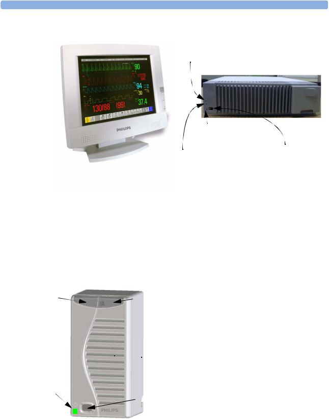
IntelliVue MP20/MP30
The IntelliVue MP20/MP30 (M8001A/M8002A) patient monitor has a 10-inch TFT LCD flat panel SVGA display. The standard input devices for the MP30 are the Touchscreen and integrated navigation point; the MP20 is supplied with an integrated navigation point only. Up to six waves can be shown on MP20/MP30 Screens (USA - up to four waves). 12 ECG traces can be shown on the 12-Lead ECG Screen.
The MP20/MP30 can be connected to one MultiMeasurement Server (MMS) and any one of the measurement server extensions. There is an optional built-in recorder. The Flexible Module Server (M8048A) and all plug-in modules cannot be used with the MP20/MP30. With an optional Interface board Bispectral Index (BIS) monitoring is possible.
MP20Junior and MP20L are options of MP20 (M8001A) and are not referred to separately in these Instructions for Use.
2
Introducing the IntelliVue Family
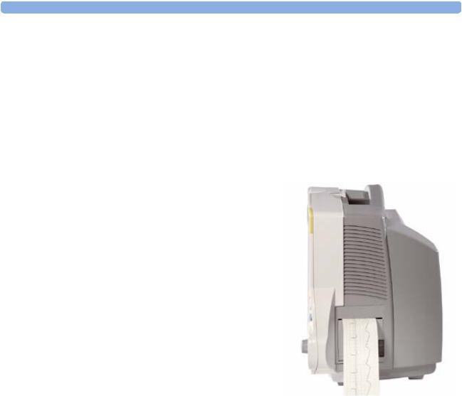
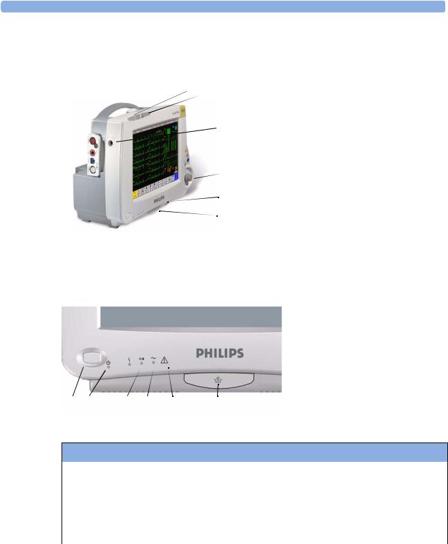
MP20/MP30 Major Parts and Keys
MP20/MP30 left side
1 2 3
 4
4
 5 6 7
5 6 7
MP20/MP30 front panel
1 |
2 |
3 |
4 |
5 |
6 |
7 |
1 Basic Operation
1Color-coded alarm lamps
2Alarms off lamp
3Model indicator
4ECG out
5Navigation Point
6Part number and serial number
7Mounting quick-release lever
1On/Standby switch
2On/Standby LED
3Error LED
4Battery status LED
5AC power operation LED
6“read the documentation” symbol
7Mounting quick-release lever
MP20/MP30 LED Colors and their Meanings
On/Standby LED |
Green when monitor is switched on |
|
|
Error LED |
Red if there is a problem with the monitor |
|
|
Battery LED |
Green, yellow, and red. |
|
See the section on Using the Batteries for details |
AC Power LED |
Green while the monitor is connected to AC power (mains) |
|
|
3
1 Basic Operation |
Introducing the IntelliVue Family |
IntelliVue MP40/MP50
The IntelliVue MP40/MP50 (M8003A/M8004A) patient monitor has a 12-inch TFT LCD flat panel SVGA display. The standard input devices for the MP50 are the Touchscreen and integrated navigation point; the MP40 is supplied with an integrated navigation point only. Up to six waves can be shown on MP40/MP50 Screens, 12 ECG traces can be shown on the 12-Lead ECG Screen.
The MP40/MP50 can be connected to one MultiMeasurement Server (MMS) and any one of the measurement server extensions. The IntelliVue family plug-in measurement modules can be connected to its
four integrated plug-in module slots with plug-and-play convenience (the only exception is the SvO2 module, M1021A, which cannot be used with the MP40/MP50). The Flexible Module Server (M8048A) cannot be used with the MP40/MP50.
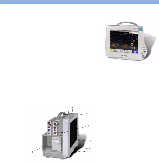
MP40/MP50 Major Parts and Keys
MP40/MP50 left side
1 Color-coded alarm lamps
2 Alarms off lamp
3 Model indicator
4 ECG out
5 Navigation Point
6 Part number and serial number
7 Mounting quick-release lever
8 Plug-in module slots
4
Introducing the IntelliVue Family |
1 Basic Operation |
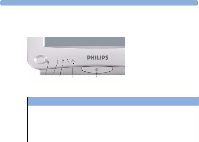
MP40/MP50 front panel
1 On/Standby switch
2 On/Standby LED
3 Error LED
4 Battery status LED
5 AC power operation LED
6 “read the documentation” symbol
7 Mounting quick-release lever
1 |
2 |
3 |
4 |
5 |
6 |
7 |
MP40/MP50 LED Colors and their Meanings
On/Standby LED |
Green when monitor is switched on |
|
|
Error LED |
Red if there is a problem with the monitor |
|
|
Battery LED |
Green, yellow, and red. |
|
See the section on Using the Batteries for details |
AC Power LED |
Green while the monitor is connected to AC power (mains) |
|
|
IntelliVue MP60/MP70
The IntelliVue MP60/MP70 (M8005A/M8007A) patient monitors integrate the display unit, with a 15” color LCD display, and the data processing unit into one. Up to eight waves can be shown on the screens, as well as the 12-Lead ECG Screen. The MP60 uses the SpeedPoint as its primary input device while the MP70 uses touch screen operation but may have an optional SpeedPoint.
The monitors can be connected to the Multi-Measurement Server (MMS) and any one of the measurement server extensions, and to the Flexible Module Server (M8048A). The IntelliVue family plug-in measurement modules can be connected to its FMS module slots with plug-and-play convenience.
The MP60/MP70 has two integrated slots for plug-in modules. You can combine one each of the following modules in these slots: Pressure, Temperature, C.O., SpO2 and VueLink. Two of the same type of module cannot be used. You can also use the two-slot recorder module in the integrated slots.
5

1 Basic Operation |
Introducing the IntelliVue Family |
MP60/MP70 Major Parts and Keys
1 |
2 |
3 |
4 |
5
11 |
10 9 |
8 |
7 |
6 |
1Color coded alarm lamps
2Alarms Off lamp
3Display
4Model indicator
5SpeedPoint (optional for MP70)
6Part number and serial number
7Mounting quick-release lever
8AC power LED
9Error LED
10Power on/standby switch
11Power on LED
IntelliVue MP80/MP90
Note: The MP80 monitor (M8008A) is not available in the USA.
The IntelliVue MP80/MP90 (M8008A/M8010A) patient monitors have the display and the processing unit as separate components. They offer both touchscreen and the Remote SpeedPoint as standard input devices. The MP80 can display up to 8 waves simultaneously and the MP90 up to 12 waves.
The monitors can be connected to the Multi-Measurement Server (MMS) and any one of the measurement server extensions, and to the Flexible Module Server (M8048A). The IntelliVue family plug-in measurement modules can be connected to its FMS module slots. The MP90 can be connected to two Flexible Module Servers (FMS). The MP90 has the capability for two displays and can have a third main display with the D80 Intelligent Display.
6
Introducing the IntelliVue Family |
1 Basic Operation |
MP80/MP90 Major Parts and Keys
AC Power LED
 Power on LED
Power on Switch
Error LED
Display Unit |
Processing Unit |
D80 Intelligent Display
The D80 Intelligent Display can be used as a third main display with the MP90 monitor. You then have three displays able to be configured individually and to be operated independently.
Remote Alarm Device
The Remote Alarm Device provides audio and visual indicators of alarms, in addition to those shown on the display.
1 |
2 |
1
2
 3
3
3
4
5
4 5
Two color coded alarm lamps (right-hand lamp flashes red or yellow for patient alarms, left-hand lamp flashes light blue for INOPs)
Alarms off lamp - when illuminated it indicates that all alarms are deactivated.
Speaker - for alarm tones, QRS tones and so forth
Monitor power on /standby switch. Press to switch monitor on remotely. Press and hold for one second to turn monitor off.
Power on LED - green when monitor is on
7
1 Basic Operation |
Related Products |
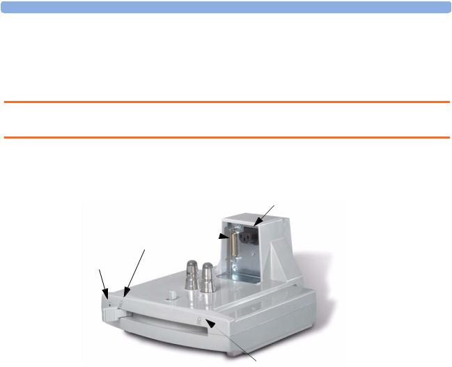
Docking Station
MP20/30/ The docking station provides quick mounting and connections in a one-step operation. By placing the 40/50 only monitor on the docking station and closing the lever you can make the connection to power and to a
wired network, if present.
WARNING If the docking station is in a tilted position, you must hold the monitor in place while closing the locking lever.
When using the monitor for transport directly after use on the docking station, insert the batteries before placing the monitor on the docking station.
Data Connector |
Power Connector |
|
Open Position
Power On LED
Locked Position
Related Products
Related products extend the measurement capabilities of your monitor. None of the related devices have their own power on/standby switches. They take their power from the monitor, and switch on automatically when you turn on the monitor. A green power-on LED indicates when they are drawing power from the monitor. A permanently illuminated, or flashing, red LED indicates a problem with the unit that requires the attention of qualified service personnel.
Flexible Module Server (M8048A)
MP60/70/80 /90 only
The flexible module server (FMS) lets you use up to eight plug-in physiological measurement modules.
With the MP60/70/80 you can connect only one FMS. With the MP90 (M8010A) you can connect two FMSs to use up to 10 measurement modules. For individual modules, the maximum that can be used simultaneously in an FMS is: five pressure modules, four temperature modules, four VueLink modules.
Connect the FMS to the monitor via the measurement server link cable (MSL). Use the MSL connector on the left-hand side to connect additional measurement servers. Use the connector on the right to connect to the monitor.
8
Related Products 1 Basic Operation
1 |
2 |
3 |
|
1 |
Multi-Measurement |
|
|
|
|
2 |
Server |
|
|
|
|
||
|
|
|
|
Measurement server |
|
|
|
|
|
|
mount |
|
|
|
|
3 |
Flexible Module Server |
|
|
|
|
4 |
Power on LED |
|
|
|
|
5 |
Interruption indicator |
|
|
4 |
5 |
|
|
Measurement Modules
You can use up to eight measurement modules with the Flexible Module Server (M8048A), two additional modules in the integrated module slots in the MP60/MP70, and up to four in the integrated slots in the MP40/MP50. Available modules are:
•Invasive blood pressure (M1006B)
•Temperature (M1029A)
•Oxygen saturation of arterial blood (SpO2) (M1020B)
•Cardiac output (M1012A), and Continuous cardiac output with M1012A Option #C10
•Transcutaneous gas (M1018A)
•Mixed venous oxygen saturation - SvO2 (M1021A) MP60/70/80/90 monitor only
•Recorder (M1116B)
•VueLink device interface (M1032A)
•EEG (M1027A)
•Bispectral Index - BIS (M1034A)
•Spirometry (M1014A)
You can plug and unplug modules during monitoring. Insert the module until the lever on the module clicks into place. Remove a module by pressing the lever upwards and pulling the module out. Reconnecting a module to the same monitor restores its label and measurement settings, such as alarms limits. If you connect it to a different monitor, the module remembers only its label.
The connector socket on the front of each module is the same color as the corresponding connector plug on the transducer or patient cable.
Press the Setup key on the module’s front to display the measurement’s setup menu on the monitor screen. When the setup menu is open, a light appears above the key. Some modules have a second key. On the pressure module, for example, it initiates a zeroing procedure.
9
1 Basic Operation |
Related Products |
Example Module (Pressure)
1Module name
2Setup key LED
3Setup key to enter setup menu of measurement modules or VueLink device data window
4Connector socket for patient cable/ transducer
5Second module-specific key, for example Zero
1
2
3
4
PRESS
Press
 5
5
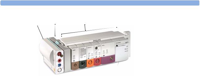
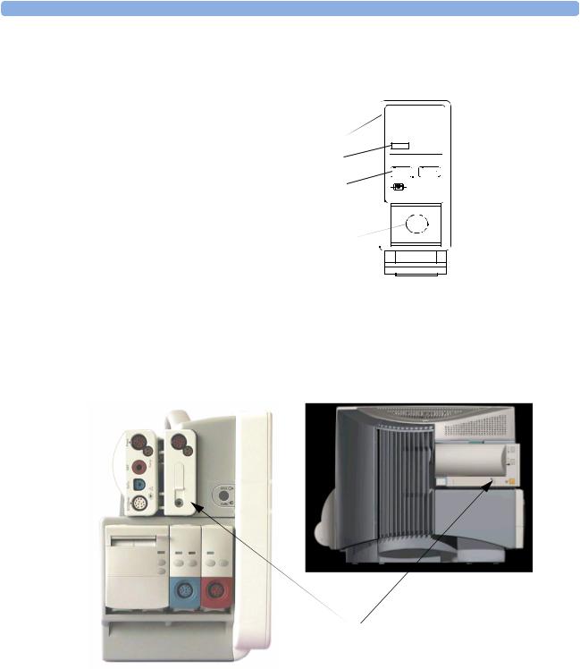
Multi-Measurement Server (M3001A)
The Multi-Measurement Server (MMS) can simultaneously monitor 3-, 5- or 10-lead ECG (including arrhythmia and ST monitoring), respiration, SpO2, NBP and either invasive pressure or temperature. Depending on the monitor model, you can connect it to the monitor via a cable or mount it either on the left side of the FMS or on the back of the monitor, as shown here.
MMS mounted on rear of MP40/MP50 (left) and MP60/MP70
10
Loading...