


 Loading...
Philips Healthcare
Cardiac Care Emergency Care Solutions |
-1/3- |
FSN86100085 2009 NOVEMBER |
URGENT – Voluntary Medical Device Correction
HeartStart Vehicle Wall Mount (Model M5528A) and DC Power Module
(Model M5529A)
Incorrect wiring during installation by user may result in a smoke or fire hazard
Dear Customer,
This letter is to inform you that a Philips investigation has found that a small number of users have modified the wiring of the HeartStart MRx Vehicle Wall Mount or the DC Power Module for the Philips HeartStart MRx defibrillator when connecting the Vehicle Wall Mount (Model M5528A) to the DC Power Module (Model M5529A). These user modifications involve cutting and splicing or soldering the DC output cable (that comes with the DC Power Module) and/or the electrical connector on the Vehicle Wall Mount.
Such improper connections can result in reversed electrical polarity from the DC Power Module to the Vehicle Wall Mount, and pose a smoke or fire hazard to patients or caregivers in proximity to the Vehicle Wall Mount. This Field Safety Notice is intended to inform you about:
•What the problem is and under what circumstances it can occur
•Actions that should be taken by the customer/user in order to mitigate risks for patients/caregivers
•Actions planned by Philips to address the problem
This document contains important information for the continued safe and proper use of your equipment
Please review the following information with all members of your staff who need to be aware of the contents of this communication. It is important to understand the implications of this communication.
Please retain a copy with the equipment Instructions for Use.
This issue can only arise when both the Vehicle Wall Mount and DC Power Module are installed together and modifications have been made to the DC Power Module power cable or Vehicle Wall Mount electrical connector. Vehicle Wall Mounts installed without a DC Power Module cannot be affected.
The HeartStart MRx monitor/defibrillator, which may be attached to the Vehicle Wall Mount, does not contribute to this issue under any circumstances and is not the subject of this correction.
1

Philips Healthcare
Cardiac Care Emergency Care Solutions |
-2/3- |
FSN86100085 2009 NOVEMBER |
Philips is updating the Instructions for Use for both the DC Power Module and the Vehicle Wall Mount with warnings to not make any unauthorized modifications to the equipment (wall mount, cables, mounting brackets, or M5529A DC Power Module). The updated Instructions for Use are included with this letter, and should be implemented to ensure the Vehicle Wall Mount and DC Power Module are installed and operated properly.
Please see the attached Field Safety Notice which provides information on how to identify affected devices and instructions on actions to be taken. Please follow the “ACTION TO BE TAKEN BY CUSTOMER / USER” section of the notice.
Should you have any questions or concerns about the Device Correction, please contact your local Philips representative:
German: |
0800 80 3000 |
French: |
0800 80 3001 |
Ensuring that you have the highest quality medical devices, accessories and supporting documentation is our top priority. Your satisfaction with Philips products as well as with our response to this problem is very important to us.
Sincerely,
Michael Miller Jr.
Senior VP and GM
Emergency Care Solutions
Cardiac Resuscitation
Attachments
2

Philips Healthcare
Cardiac Care Emergency Care Solutions |
-3/3- |
FSN86100085 2009 NOVEMBER |
AFFECTED PRODUCTS
PROBLEM
DESCRIPTION
HAZARD INVOLVED
HOW TO IDENTIFY AFFECTED PRODUCTS
ACTION TO BE TAKEN BY CUSTOMER / USER
ACTIONS PLANNED BY PHILIPS
FURTHER INFORMATION AND SUPPORT
Field Safety Notice
Product: Philips HeartStart Wall Mount, Model M5528A (if used with DC Power Module, Model M5529A).
Units Affected: Units distributed by Philips and shipped between September 1, 2004 and October 1, 2009.
Distributed by: Philips Healthcare, 3000 Minuteman Road, Andover, MA, 01810.
A small number of users have modified the wiring of the HeartStart Vehicle Wall Mount for the Philips HeartStart MRx monitor/defibrillator when connecting the Vehicle Wall Mount to the DC Power Module (Model M5528A), as part of installation. These modifications involve cutting and splicing or soldering the DC output cable from the DC Power Module and/or the electrical connector on the Wall Mount. Such incorrect installation may result in reversing the electrical polarity of the connection, which can lead to excessive heating at the lower mounting bracket of the Vehicle Wall Mount, where it interfaces with the monitor/defibrillator.
Elevated temperatures at the lower mounting bracket on the Vehicle Wall Mount can melt the plastic mounting bracket and smoke. If not promptly detected, combustion of the assembly may result. These events could result in exposure of patients or caregivers to smoke or fire, particularly if they are in an enclosed space, such as an ambulance. Furthermore, resulting damage to the ambulance or to the monitor/defibrillator could disrupt patient care.
See affected products above.
Immediately check all Vehicle Wall Mounts to verify that either (1) they are not connected to a DC Power Module or (2) that there is a proper connection between the two. The latter can be verified by checking whether the green external power indicator on a HeartStart MRx mounted on the Vehicle Wall Mount is lit when power is supplied to the DC Power Module.
If you cannot verify either of the two conditions above, immediately disconnect the power to DC Power Module, and contact your local representative.
Note: In any case, the associated HeartStart MRx is not affected and can remain in service.
Philips is voluntarily initiating a corrective action consisting of:
•Issuance of a procedure for identification of incorrect installations as described in this Field Safety Notice
•Issuance of revised Instructions for Use for Vehicle Wall Mount for HeartStart MRx and DC Power Module for the HeartStart MRx including a revised description of correct installation and verification of performance
If you need any further information or support concerning this issue, please contact your local Philips representative at:
German: 0800 80 3000
French: 0800 80 3001
3

M5528A
HeartStart MRx
Vehicle Wall Mount
Dispositif de fixation du HeartStart MRx pour véhicules de secours
Supporto a parete per uso su veicoli per HeartStart MRx
HeartStart MRx
Wandhalterung für
Fahrzeuge
Soporte de pared para vehículos del HeartStart MRx
HeartStart MRx Wandmontagesysteem voor voertuigen
HeartStart MRx - Suporte de parede para veículos
HeartStart MRx
HeartStart MRx
MRx
1

ENGLISH |
HeartStart MRx Vehicle Wall Mount |
HeartStart MRx Vehicle Wall Mount
The M5528A HeartStart MRx Vehicle Wall Mount (VWM) is designed to hold the
HeartStart MRx Monitor/Defibrillator (M3536A) during transport. The typical use is within an ambulance.
Unpacking
Table 1 |
Package Content |
|
|
|
|
Item |
|
Quantity |
|
|
|
HeartStart MRx Vehicle Wall Mount |
1 |
|
Instructions for Use |
1 |
|
Vehicle Mounting template |
1 |
|
Upper Mounting Bracket |
1 |
|
screws for Upper Mounting Bracket (12 mm) |
2 |
|
Lower Mounting Bracket |
1 |
|
screws for Lower Mounting Bracket (14 mm) |
2 |
|
|
|
|
Installation
Installation of the VWM should be performed by a qualified mechanical and electrical technician.
Selecting the VWM Location
The VWM is typically mounted on the left or right interior panels of the vehicle, or on the interior panel directly behind the driver's seat. The VWM must be screwed to the chassis of the vehicle. This prevents it from becoming detached during normal use and in extreme situations such as in a collision.
CAUTION: When the VWM is fastened to the wall, the wall and screws must withstand a force of at least 330 lb (150 kg) in all directions. Do not attach the VWM to the vehicle doors.
When identifying a suitable location for the VWM to be mounted:
Select a flat surface to support the VWM.
Allow sufficient space at each side of the VWM to accommodate the use of side accessory pouches on the HeartStart MRx (see Figure 1).
Allow sufficient space at the top of the unit to accommodate operation of the release handle.
2
HeartStart MRx Vehicle Wall Mount |
ENGLISH |
NOTE: The HeartStart MRx cannot be inserted into the VWM when any one of the following is attached:
–the rear accessory pouch,
–the bedrail hook,
–the M3539A AC power module.
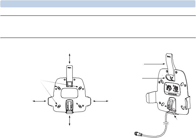
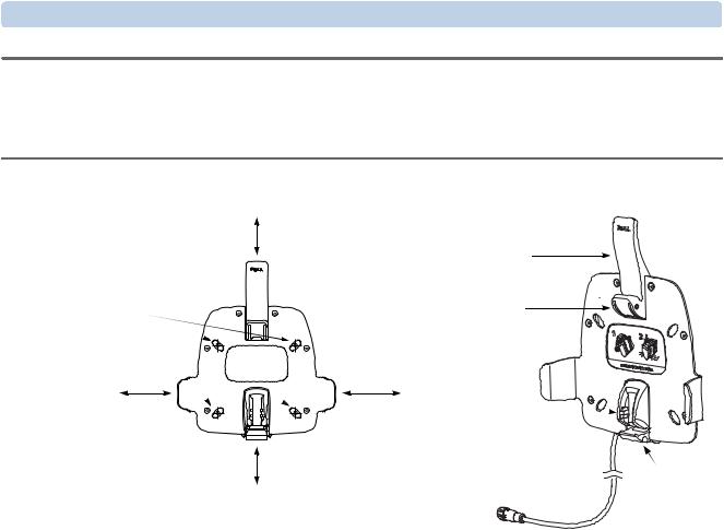
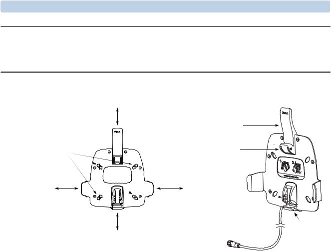
Figure 1 Positioning of the Mounting Frame and Wall Mount Elements
Min. 4” (100 mm)
Release
Lever
drill
locations  Upper Hook
|
|
HeartStart MRx |
|
|
|
electrical |
|
Min. 6” |
Min. 6” |
interface |
|
contacts |
|
||
(150 mm) |
(150 mm) |
|
|
|
|
||
|
Min. 4” (100 mm) |
cable to the |
|
|
M5529A DC |
Lower |
|
|
|
||
|
|
Power Module |
Hook |
Preparing the HeartStart MRx
To prepare the HeartStart MRx for wall mount:
1Remove the rear accessory pouch and bedrail hook (if installed).
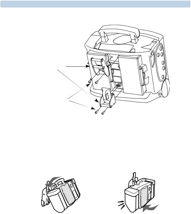
2Using a Torx T-20 screwdriver, screw the two mounting brackets into the MRx (see Figure 2). Note that the 14-mm screws are for the lower bracket, and the 12-mm screws are for the upper bracket. Apply 1.1 Nm (10 inch-lb) of torque when inserting the screws.
3

ENGLISH |
HeartStart MRx Vehicle Wall Mount |
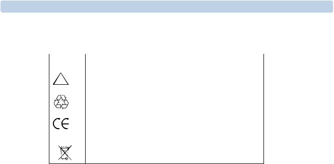
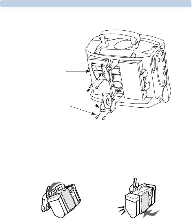
Figure 2 HeartStart MRx Vehicle Wall Mount Preparation
Upper and
Lower Mounting
Brackets
screws
Operation
To Insert the HeartStart MRx into the VWM:
1Place the Upper Mounting Bracket over the hook of the release handle (see Figure 3).
2Push the lower part of the MRx into the VWM.
You should feel the lower mounting bracket lock into place.
Figure 3 HeartStart MRx Operation
|
|
TIP: If the device does not click into place, check that no objects interfere with the locking mechanism.
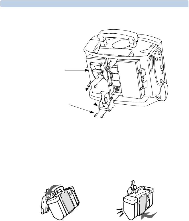
Use the DC Power Supply module (M5529A, see Figure 4) or a Philips-approved battery support system to charge the HeartStart MRx batteries in transport. If you do not use the DC Power Supply module, then tuck the DC Power Supply output cable away.
4

HeartStart MRx Vehicle Wall Mount |
ENGLISH |
Figure 4 Connecting the VWM to the DC Power Supply (optional)
DC Power Supply output cable
HeartStart MRx
DC Power Supply
to the vehicle battery power
Performance Verification
To verify installation:
Check that the VWM is securely mounted to the interior vehicle panel.
Check that the Upper and Lower Mounting Brackets are securely fastened to the HeartStart MRx.
Check that the HeartStart MRx can easily be installed into the VWM, as described in “Operation” on page 4.
Pull forward the front bottom portion of the MRx to ensure that it is securely mounted in position. Check that you can remove the MRx from the bracket by pulling on the release handle.
If you use the M5529A HeartStart MRx DC Power Module, then:
aInsert one or two batteries into the HeartStart MRx.
bInstall the HeartStart MRx into the VWM.
cConnect the DC Power Module to the vehicle battery.
dVerify that the green External Power indicator at the upper right corner of the HeartStart MRx screen is on.
If any of the verification steps fail, then stop using the VWM and correct the installation.
5

ENGLISH |
HeartStart MRx Vehicle Wall Mount |
Safety Considerations
WARNINGS: • Electrical shock hazard exists. Do not touch metal contacts.
•Do not perform any unauthorized modification to the equipment (wall mount, cables, mounting brackets, or M5529A DC Power Module, if used in installation).
•Do not mount the VWM directly below infusion pumps or other similar equipment where there is a possibility of liquid spill.
Maintenance
The VWM has no internal electronics that require maintenance.
Verify the installation every month. In addition to the performance verification (see “Performance Verification” on page 5), watch for:
–frayed cables,
–worn and oxidized contacts,
–loose mechanical joints.
Clean the VWM with a damp cloth using mild soap and water.
Repair
The VWM has no serviceable parts. The repair philosophy for the VWM is unit replacement. For information on ordering, call 1-800-225-0230 or visit our website at: http://philips.com/healthcarestore.
Specifications
Standards
IEC 60601-1 (2001), IEC 60601-1-2 (2001), EN 1789 (1999)
Physical
Weight (excluding cables): 1.5 kg (3.3 lb)
Dimensions (L x W x H): 75 x 300 x 320 mm (3.0" x 11.2" x 12.6")
Environmental
Temperature: Operating: 0o—40oC (32—104oF); Storage: –30o—70oC (–22—158oF)
Humidity: 5%—95% non-condensing
Altitude: –500—7500 m (–1,500—25,000 ft)
6
HeartStart MRx Vehicle Wall Mount |
ENGLISH |
Symbol Definitions
Table 2 |
VWM Packaging Symbols |
|
|
|
|
Symbol |
Definition |
|
|
|
|
! |
Attention – See operating instructions in HeartStart MRx |
|
Instructions for Use. |
||
|
||
|
Recyclable material. |
This device complies with the requirements of the Medical
Device Directive 93/42/EEC.
WEEE |
This appliance is marked according to the European directive |
||
|
|
|
2002/96/EC on Waste Electrical and Electronic Equipment |
|
|
|
|
|
|
|
(WEEE). Dispose of in accordance with local regulations. |
7
FRANÇAIS |
Dispositif de fixation du HeartStart MRx pour véhicules de secours |
Dispositif de fixation du HeartStart MRx pour véhicules de secours
Le dispositif de fixation du HeartStart MRx pour véhicules de secours M5528A permet de maintenir le défibrillateur/moniteur HeartStart MRx (M3536A) en position pendant le transport. Il est spécialement conçu pour être utilisé dans les ambulances.
Eléments du kit
Tableau 1 Contenu de l’emballage
Elément |
Quantité |
|
|
Dispositif de fixation du HeartStart MRx pour |
1 |
véhicules de secours |
|
Manuel d’utilisation |
1 |
Gabarit de montage pour fixation dans les véhicules |
1 |
Support de montage supérieur |
1 |
Vis pour le support de montage supérieur (12 mm) |
2 |
Support de montage inférieur |
1 |
Vis pour le support de montage inférieur (14 mm) |
2 |
|
|
Installation
L’installation du dispositif de fixation doit être effectuée par un technicien/électricien qualifié.
Choix de l’emplacement de fixation
Vous pouvez installer le dispositif de fixation sur le panneau latéral intérieur, gauche ou droit, du véhicule, ou directement derrière le siège du conducteur. Il doit être vissé sur le châssis du véhicule, afin de ne pas bouger pendant l’utilisation normale ou lors de situations extrêmes telles qu’une collision.
ATTENTION : Après fixation du dispositif, la paroi et les vis doivent supporter l’application d’une force d’au moins 150 kg dans toutes les directions. Ne fixez pas le dispositif aux portières d’un véhicule.
Choisissez un emplacement approprié pour monter ce dispositif :
Sélectionnez une surface parfaitement plane pour servir de support au dispositif.
Prévoyez un espace suffisant sur les côtés du dispositif pour pouvoir accéder facilement aux sacoches latérales contenant les accessoires du HeartStart MRx (voir la Figure 1).
Prévoyez aussi un espace suffisant au-dessus de l’appareil pour pouvoir activer la poignée de déverrouillage.
8

Dispositif de fixation du HeartStart MRx pour véhicules de secours |
FRANÇAIS |
REMARQUE : Il est impossible d’insérer le HeartStart MRx dans le dispositif de fixation lorsque les éléments suivants sont installés sur celui-ci :
–sacoche à accessoires arrière,
–crochet de montage,
–module d’alimentation CA M3539A.
Figure 1 Positionnement du support de montage et des éléments du dispositif de fixation
100 mm min.
Poignée de
déverrouillage
Emplacements
des trous à
Crochet
percer 
 supérieur
|
|
Contacts |
|
|
|
d’interface |
|
150 mm |
150 mm |
électrique avec le |
|
HeartStart MRx |
|
||
min. |
min. |
|
|
|
|
||
100 mm min. |
|
Câble de raccordement |
Crochet |
|
|
au module d’alimentation |
|
|
|
CC M5529A |
inférieur |
Préparation du HeartStart MRx
Pour préparer la fixation du HeartStart MRx au dispositif, procédez comme suit :
1Retirez la sacoche à accessoires arrière et le crochet de montage (le cas échéant).
2A l’aide d’un tournevis Torx T-20, vissez les deux supports de montage sur le MRx (voir la Figure 2). Les vis de 14 mm sont destinées au support inférieur. Les vis de 12 mm sont destinées au support supérieur. Appliquez un couple de serrage de 1,1 Nm pour fixer les vis.
9
FRANÇAIS |
Dispositif de fixation du HeartStart MRx pour véhicules de secours |
Figure 2 Préparation du dispositif de fixation du HeartStart MRx pour véhicules de secours
Supports de montage supérieur et inférieur
Vis
Mise en place
Pour insérer le HeartStart MRx dans le dispositif de fixation, procédez comme suit :
1Positionnez le crochet de la poignée de déverrouillage sur le support de montage supérieur (voir la Figure 3).
2Baissez la partie inférieure du MRx pour l’enclencher sur le dispositif.
Vous devez sentir que le support de montage inférieur est bien mis en place.
Figure 3 Mise en place du HeartStart MRx |
|
|
|
CONSEIL : Si vous n’entendez pas de clic indiquant que l’appareil est enclenché, vérifiez qu’aucun objet ne bloque le mécanisme de verrouillage.
Utilisez le module d’alimentation CC (M5529A, voir la Figure 4) ou un support de batterie approuvé par Philips pour recharger les batteries du HeartStart MRx pendant le transport. Si vous n’utilisez pas le module d’alimentation CC, rangez le câble de sortie de celui-ci.
10
Dispositif de fixation du HeartStart MRx pour véhicules de secours |
FRANÇAIS |
Figure 4 Raccordement du dispositif de fixation au module d’alimentation CC
(facultatif)
Câble de sortie du module d’alimentation CC
Module d’alimentation CC du HeartStart MRx
Vers la batterie du véhicule
Vérification de l’installation
Pour vérifier que l’installation est correcte, procédez comme suit :
Assurez-vous que le dispositif est bien fixé sur le panneau intérieur du véhicule.
Vérifiez que les supports de montage supérieur et inférieur du HeartStart MRx sont bien fixés sur l’appareil.
Assurez-vous que le HeartStart MRx puisse être facilement installé sur le dispositif de fixation (reportez-vous à la procédure décrite au titre ci-dessus “Mise en place”, page 10).
Tirez sur la partie inférieure du panneau avant du MRx pour vérifier qu’il est bien en position.
Vérifiez que vous pouvez dégager le MRx du dispositif de fixation en tirant sur la poignée de déverrouillage.
Si vous utilisez le module d’alimentation CC M5529A du HeartStart MRx, procédez comme suit :
aInsérez une ou deux batteries dans le HeartStart MRx.
bInstallez le HeartStart MRx dans le dispositif de fixation.
cBranchez le module d’alimentation CC sur la batterie du véhicule.
dAssurez-vous que l’indicateur d’alimentation externe vert, situé dans l’angle supérieur droit de l’écran du HeartStart MRx, s’allume.
Si vous détectez un problème pendant cette vérification, cessez toute utilisation du dispositif de fixation et modifiez l’installation.
11

FRANÇAIS |
Dispositif de fixation du HeartStart MRx pour véhicules de secours |
Consignes de sécurité
AVERTISSEMENTS :
•Afin d’éviter tout risque de choc électrique, ne touchez pas les contacts métalliques.
•N’apportez aucune modification non autorisée aux équipements (dispositif de fixation, câbles, supports de montage ou module d’alimentation CC M5529A, le cas échéant).
•N’installez pas le dispositif de fixation directement sous des pompes à perfusion ou sous tout autre équipement similaire contenant du liquide susceptible de fuir.
Entretien
Le dispositif de fixation ne contient aucune pièce électronique nécessitant une maintenance.
Procédez à une vérification mensuelle de l’installation. En plus de la vérification de l’installation (reportez-vous à la section “Vérification de l’installation”, page 11), assurez-vous :
–que les câbles ne sont pas endommagés,
–qu’aucun contact n’est usé ni oxydé,
–que les joints mécaniques ne sont pas lâches.
Pour nettoyer le dispositif de fixation, utilisez un chiffon imbibé d’eau savonneuse.
Maintenance
Aucune pièce du dispositif de fixation n’est réparable. Si le dispositif est endommagé, il doit être remplacé. Pour plus d’informations sur la procédure à suivre pour commander un équipement, appelez le 1-800-225-0230 ou consultez le site : http://philips.com/healthcarestore.
Caractéristiques techniques
Conformité aux normes
CEI 60601-1 (2001), CEI 60601-1-2 (2001), EN 1789 (1999)
Caractéristiques physiques
Masse (sans les câbles) : 1,5 kg
Dimensions (L x l x H) : 75 x 300 x 320 mm
Caractéristiques d’environnement
Température : en fonctionnement : 0 oC à 40 oC ; en stockage : –30 oC à 70 oC
Humidité : 5 % à 95 % sans condensation
Altitude : –500 à 7 500 m
12
Dispositif de fixation du HeartStart MRx pour véhicules de secours |
FRANÇAIS |
Signification des symboles
Tableau 2 Symboles figurant sur le dispositif et sur l’emballage
Symbole |
Signification |
|
|
|
|
! |
Attention – Reportez-vous aux instructions de |
|
fonctionnement du Manuel d’utilisation du HeartStart MRx. |
||
|
||
|
Matériel recyclable. |
Cet appareil est conforme aux exigences essentielles de la Directive européenne 93/42/CEE relative aux dispositifs médicaux.
WEEE |
Cet appareil est conforme à la Directive européenne |
||
|
|
|
2002/96/CE concernant la mise au rebut des équipements |
|
|
|
|
|
|
|
électriques et électroniques (WEEE). Procédez à la mise au |
|
|
|
rebut conformément à la législation en vigueur. |
13

ITALIANO |
Supporto a parete per uso su veicoli per HeartStart MRx |
Supporto a parete per uso su veicoli per HeartStart MRx
Il Supporto a parete per uso su veicoli per HeartStart MRx (VWM) M5528A è un dispositivo ideato per sostenere Monitor/defibrillatore HeartStart MRx (M3536A) durante il trasporto, generalmente all'interno delle ambulanze.
Disimballaggio
Tabella 1 Contenuto dell'imballaggio
Voce |
Quantità |
|
|
Supporto a parete per uso su veicoli per HeartStart MRx |
1 |
Istruzioni d'uso |
1 |
Schema per il montaggio nel veicolo |
1 |
Staffa di montaggio superiore |
1 |
Viti per staffa di montaggio superiore (12 mm) |
2 |
Staffa di montaggio inferiore |
1 |
Viti per staffa di montaggio inferiore (14 mm) |
2 |
|
|
Installazione
Il montaggio del supporto a parete deve essere eseguito da un tecnico elettricista e meccanico specializzato.
Identificazione della posizione di montaggio del supporto a parete
Il supporto a parete viene solitamente installato sul pannello interno destro o sinistro del veicolo o sul pannello interno direttamente dietro il sedile del guidatore e va fissato con delle viti al telaio del veicolo. Ciò previene l'eventuale distacco del dispositivo durante il normale utilizzo oppure in situazioni estreme a seguito, ad esempio, di una collisione.
ATTENZIONE: una volta fissato il supporto, la parete e le viti devono sostenere una forza di almeno 330 lb (150 kg) in tutte le direzioni. Non fissare il supporto a parete alle porte del veicolo.
Una volta identificata la posizione di montaggio appropriata, procedere come segue:
Individuare una superficie piana su cui appoggiare il supporto.
Lasciare spazio sufficiente ai lati del supporto per consentire l'utilizzo delle tasche per gli accessori di HeartStart MRx (vedere la Figura 1).
Lasciare spazio sufficiente sopra l'unità per consentire lo spostamento della maniglia di rilascio.
14

Supporto a parete per uso su veicoli per HeartStart MRx |
ITALIANO |
NOTA: HeartStart MRx non può essere inserito nel supporto a parete quando è presente uno dei seguenti elementi:
–Tasca degli accessori posteriore
–Gancio per sponda del letto
–Modulo alimentatore CA M3539A
Figura 1 Posizionamento del telaio di montaggio e degli elementi del supporto a parete
Min. 100 mm
Leva di rilascio
Posizione
dei fori  Gancio superiore
|
|
|
Contatti |
|
|
|
|
interfaccia |
|
Min. |
|
Min. 150 mm |
elettrica |
|
|
HeartStart MRx |
|
||
150 mm |
|
|
|
|
|
|
|
|
|
|
Min. 100 mm |
|
Cavo a modulo |
|
|
|
alimentatore CC |
Gancio |
|
|
|
|
||
|
|
|
M5529A |
inferiore |
Predisposizione di HeartStart MRx
Per preparare HeartStart MRx per il supporto a parete:
1Rimuovere la tasca degli accessori posteriore e il gancio per sponda del letto (se presente).
2Utilizzando un cacciavite Torx T-20, fissare le due staffe di montaggio al dispositivo MRx (vedere la Figura 2).
Le viti da 14 mm sono da utilizzare per la staffa inferiore mentre le viti da 12 mm sono da utilizzare per la staffa superiore. Applicare una forza di 1,1 Nm per fissare le viti.
15
ITALIANO |
Supporto a parete per uso su veicoli per HeartStart MRx |
Figura 2 Predisposizione del Supporto a parete per uso su veicoli per
HeartStart MRx
Staffe di montaggio superiore e inferiore
Viti
Funzionamento
Per inserire HeartStart MRx nel supporto a parete:
1Posizionare la staffa di montaggio superiore sul gancio della maniglia di rilascio (vedere la Figura 3).
2Spingere la parte inferiore del dispositivo MRx nel supporto a parete. Spingere finché la staffa di montaggio inferiore non scatta in posizione.
Figura 3 Funzionamento dell'HeartStart MRx
|
|
SUGGERIMENTO: se il dispositivo non scatta in posizione, verificare che non ci siano elementi che interferiscono con il meccanismo di blocco.
Utilizzare il modulo alimentatore CC (M5529A, vedere la Figura 4) o un sistema per la ricarica delle batterie approvato da Philips per caricare le batterie di HeartStart MRx durante il trasporto. Se non viene utilizzato un modulo alimentatore CC, riporre il relativo cavo.
16

Supporto a parete per uso su veicoli per HeartStart MRx |
ITALIANO |
Figura 4 Collegamento del supporto a muro all'alimentatore CC (opzionale)
Cavo di uscita alimentatore CC
Alimentatore CC
HeartStart MRx
Alla batteria del veicolo
Verifica del funzionamento
Per verificare l'installazione:
Verificare che il supporto a parete sia fissato saldamente al pannello interno del veicolo.
Verificare che le staffe di montaggio superiore e inferiore siano fissate saldamente a HeartStart MRx.
Controllare che HeartStart MRx possa essere facilmente installato sul supporto, come descritto in "Funzionamento" a pagina 16.
Tirare in avanti la parte anteriore in basso del dispositivo MRx per assicurarsi che sia fissata correttamente.
Verificare che l'MRx possa essere rimosso dalla staffa tirando la maniglia di rilascio.
Se si utilizza un modulo alimentatore CC M5529A per HeartStart MRx:
aInserire una o due batterie all'interno di HeartStart MRx.
bMontare HeartStart MRx nel supporto a parete.
cCollegare il modulo alimentatore CC alla batteria del veicolo.
dVerificare che la spia di alimentazione esterna verde nell'angolo superiore destro dello schermo di HeartStart MRx sia accesa.
Se una qualsiasi di queste verifiche non ha esito positivo, non utilizzare il supporto e correggerne l'installazione.
17
ITALIANO |
Supporto a parete per uso su veicoli per HeartStart MRx |
Considerazioni sulla sicurezza
AVVERTENZE: • Pericolo di scosse elettriche. Evitare il contatto con oggetti metallici.
•Non apportare modifiche non autorizzate all'apparecchiatura (supporto a parete, cavi, staffe di montaggio o modulo alimentatore CC M5529A, se utilizzato).
•Non installare il supporto a parete direttamente sotto le pompe di infusione o dispositivi simili dove sussista il pericolo di versamento di liquidi.
Manutenzione
Il supporto non è dotato di parti elettroniche interne che richiedono manutenzione.
Si consiglia di ispezionare l'installazione mensilmente. Oltre al controllo delle prestazioni (vedere la "Verifica del funzionamento" a pagina 17), verificare l'eventuale presenza di quanto segue:
–cavi sfilacciati
–contatti usurati e ossidati
–giunti meccanici allentati
Pulire il supporto a parete con un panno inumidito con acqua e sapone neutro.
Riparazione
Il supporto a parete non contiene parti riparabili. In caso di rotture o danni, è necessario sostituire l'intera unità. Per informazioni sull'ordinazione, chiamare il numero 1-800-225-0230 oppure visitare il nostro sito Web: http://philips.com/healthcarestore.
Specifiche
Standard
IEC 60601-1 (2001), IEC 60601-1-2 (2001), EN 1789 (1999)
Specifiche fisiche
Peso (cavi esclusi): 1,5 kg
Dimensioni (Lungh. x Largh. x H): 75 x 300 x 320 mm
Specifiche ambientali
Temperatura: in funzione: 0o—40oC; in magazzino: –30o—70oC
Umidità: 5%—95% senza condensa
Altitudine: –500—7500 m
18
Supporto a parete per uso su veicoli per HeartStart MRx |
ITALIANO |
Definizione dei simboli
Tabella 2 Simboli dell'imballaggio del supporto a parete
Symbol |
Definition |
|
|
|
|
! |
Attention – See operating instructions in HeartStart MRx |
|
Instructions for Use. |
||
|
||
|
Recyclable material. |
This device complies with the requirements of the Medical
Device Directive 93/42/EEC.
WEEE |
This appliance is marked according to the European directive |
||
|
|
|
2002/96/EC on Waste Electrical and Electronic Equipment |
|
|
|
|
|
|
|
(WEEE). Dispose of in accordance with local regulations. |
19

Deutsch |
HeartStart MRx Wandhalterung für Fahrzeuge |
HeartStart MRx Wandhalterung für Fahrzeuge
Die HeartStart MRx Wandhalterung für Fahrzeuge (M5528A) ist zur Befestigung des HeartStart MRx Monitors/Defibrillators (M3536A) beim Transport konzipiert. In der Regel wird das Produkt in einem Rettungswagen verwendet.
Lieferumfang
Tabelle 1 Packungsinhalt
Element |
Menge |
|
|
HeartStart MRx Wandhalterung für Fahrzeuge |
1 |
Gebrauchsanweisung |
1 |
Schablone zur Befestigung im Fahrzeug |
1 |
Obere Montageklemme |
1 |
Schrauben für obere Montageklemme (12 mm) |
2 |
Untere Montageklemme |
1 |
Schrauben für untere Montageklemme (14 mm) |
2 |
|
|
Installation
Die Installation der Wandhalterung ist von einem qualifizierten Mechaniker bzw. Elektrotechniker vorzunehmen.
Auswählen der Befestigungsposition
Die Wandhalterung wird in der Regel entweder an der rechten oder linken Seitenwand im Fahrzeug oder direkt hinter dem Fahrersitz angebracht. Die Wandhalterung muss am Fahrzeuggehäuse angeschraubt werden. Dadurch wird verhindert, dass sich die Wandhalterung unter normalen Bedingungen oder in Extremsituationen, wie beispielsweise einer Kollision, löst.
ACHTUNG: Wenn die Wandhalterung an der Fahrzeugwand befestigt wird, müssen Wand und Schrauben einer Kraft von mindestens 1500 N in alle Richtungen standhalten. Die Wandhalterung nicht an den Fahrzeugtüren anbringen.
Bei der Auswahl einer geeigneten Position zur Befestigung der Wandhalterung im Fahrzeug:
Eine ebene Oberfläche zur Befestigung auswählen.
Zu beiden Seiten der Wandhalterung ausreichend Platz lassen, um einen leichten Zugang zu den seitlichen Zubehörtaschen am HeartStart MRx zu ermöglichen (siehe Abbildung 1).
Über der Wandhalterung ausreichend Platz lassen, um eine leichte Betätigung des Ausklinkhebels zu ermöglichen.
20
HeartStart MRx Wandhalterung für Fahrzeuge |
Deutsch |
HINWEIS: Der HeartStart MRx kann nicht in die Wandhalterung eingesetzt werden, wenn eines der folgenden Zubehörteile angebracht ist:
–hintere Zubehörtasche
–Haken für die Bettschiene
–Wechselstrom-Netzmodul M3539A
Abbildung 1 Platzieren von Montagerahmen und Wandhalterungselementen
min. 100 mm
|
|
|
Ausklinkhebel |
|
Bohrlöcher |
|
|
Oberer |
|
|
|
|
|
|
|
|
|
Haken |
|
|
|
|
Elektrische |
|
|
|
|
Kontakte des |
|
min. |
|
min. |
HeartStart MRx |
|
|
|
|
||
150 mm |
|
150 mm |
|
|
|
min. 100 mm |
|
Kabel zum |
|
|
|
Gleichstrom-Netzmodul |
Unterer |
|
|
|
|
||
|
|
|
M5529A |
Haken |
Vorbereiten des HeartStart MRx
Den HeartStart MRx wie folgt für die Wandbefestigung vorbereiten:
1Die hintere Zubehörtasche und den Haken für die Bettschiene (sofern verwendet) abnehmen.
2Die zwei Montageklemmen mit einem Torx T20-Schraubendreher am MRx befestigen (siehe Abbildung 2).
Die 14-mm-Schrauben sind für die untere Montageklemme bestimmt, die 12-mm-Schrauben für die obere. Die Schrauben mit einem Drehmoment von 1,1 Nm festziehen.
21
Deutsch |
HeartStart MRx Wandhalterung für Fahrzeuge |
Abbildung 2 Vorbereiten des HeartStart MRx Wandhalterung für Fahrzeuge
Obere und untere
Montageklemme
Schrauben
Verwendung
Zum Einsetzen des HeartStart MRx in die Wandhalterung wie folgt vorgehen:
1Die obere Montageklemme über dem Haken des Ausklinkhebels positionieren (siehe Abbildung 3).
2Den unteren Teil des MRx vorsichtig in die Wandhalterung drücken. Die untere Montageklemme sollte spürbar einrasten.
Abbildung 3 Verwenden des HeartStart MRx
|
|
TIPP: Wenn das Gerät nicht richtig einrastet, überprüfen, ob der Verriegelungsmechanismus durch andere Gegenstände blockiert wird.
Zum Laden der Akkus des HeartStart MRx beim Transport das Gleichstrom-Netzmodul (M5529A, siehe Abbildung 4) oder eine von Philips zugelassenen Ladestation verwenden. Falls das Gleich- strom-Netzmodul nicht verwendet wird, das Gleichstrom-Ausgangskabel wegstecken.
22

HeartStart MRx Wandhalterung für Fahrzeuge |
Deutsch |
Abbildung 4 Anschließen der Wandhalterung an das Gleichstrom-Netzmodul
(optional)
Gleichstrom-
Ausgangskabel
HeartStart MRx
Gleichstrom-Netzmodul
Anschluss an
Fahrzeugbatterie
Leistungsnachweistest
Zum Überprüfen der Installation wie folgt vorgehen:
Prüfen, ob die Wandhalterung für Fahrzeuge fest an der Innenseite des Fahrzeugs befestigt ist.
Prüfen, ob obere und untere Montageklemme fest am HeartStart MRx befestigt sind.
Sicherstellen, dass der HeartStart MRx wie unter "Verwendung" auf Seite 22 beschrieben leicht in die Wandhalterung eingesetzt werden kann.
Den vorderen, unteren Teil des MRx zum Körper ziehen, um sicherzustellen, dass dieser sicher befestigt ist.
Sicherstellen, dass der MRx durch Ziehen des Ausklinkhebels wieder aus der Wandhalterung herausgenommen werden kann.
Bei Verwendung des HeartStart MRx Gleichstrom-Netzmoduls M5529A:
aEinen oder zwei Akkus in den HeartStart MRx einsetzen.
bDen HeartStart MRx in die Wandhalterung einsetzen.
cDas Gleichstrom-Netzmodul an die Fahrzeugbatterie anschließen.
dÜberprüfen, ob die grüne Leuchtanzeige für die externe Stromquelle oben rechts auf der Anzeige des HeartStart MRx leuchtet.
Wenn einer der angegebenen Punkte nicht erfolgreich überprüft werden kann, die Wandhalterung nicht weiter verwenden und die Installation korrigieren.
23

Deutsch |
HeartStart MRx Wandhalterung für Fahrzeuge |
Sicherheitshinweise
WARNUNGEN:
•Stromschlaggefahr besteht. Metallische Gegenstände nicht berühren.
•Keine nicht autorisierten Änderungen an den Komponenten vornehmen (Wandhalterung, Kabel, Montageklemmen, Gleichstrom-Netzmodul M5529A (sofern verwendet)).
•Die Wandhalterung nicht direkt unter Infusionspumpen oder ähnlicher Ausrüstung, bei der Flüssigkeit auf das Gerät gelangen kann, befestigen.
Wartung
Die Wandhalterung besitzt keine interne Elektronik, die gewartet werden muss.
Die Installation einmal monatlich überprüfen. Neben dem Leistungsnachweistest (siehe "Leistungsnachweistest" auf Seite 23) auf Folgendes achten:
–abgenutzte Stellen an den Kabeln
–verschlissene oder korrodierte Kontakte
–lose mechanische Verbindungen
Zum Reinigen der Wandhalterung ein feuchtes Tuch, milde Seife und Wasser verwenden.
Reparatur
Die Wandhalterung besitzt keine zu wartenden Teile. Wenn die Wandhalterung beschädigt ist, muss sie vollständig ersetzt werden. Für Informationen zur Bestellung wählen Sie bitte +1-800-225-0230 oder besuchen Sie unsere Website unter http://philips.com/healthcarestore.
Technische Daten
Standards
IEC 60601-1 (2001), IEC 60601-1-2 (2001), EN 1789 (1999)
Abmessungen und Gewicht
Gewicht (ohne Kabel): 1,5 kg
Abmessungen (L x B x H): 75 x 300 x 320 mm
Umgebungsbedingungen
Temperatur: Betrieb: 0–40 °C; Lagerung: -30–70 °C
Relative Luftfeuchtigkeit: 5%–95% (nicht kondensierend)
Höhe ü.d.M.: -500–7500 m
24
HeartStart MRx Wandhalterung für Fahrzeuge |
Deutsch |
Symboldefinitionen
Tabelle 2 Symbole auf der Verpackung
Symbol |
Definition |
|||||
|
|
|
|
|
|
|
! |
|
|
|
Achtung – siehe Betriebsanleitungen in der HeartStart MRx |
||
|
|
|
Gebrauchsanweisung. |
|||
|
|
|
|
|
||
|
|
|
|
|
Wiederverwertbares Material. |
|
|
|
|
|
|
Entspricht der Richtlinie 93/42/EWG des Rates vom |
|
|
|
|
|
|
14. Juni 1993 für Medizinprodukte. |
|
WEEE |
||||||
Markierung gemäß EU-Richtlinie 2002/96/EC zur Entsor- |
||||||
|
|
|
|
|
gung von elektrischen und elektronischen Geräten (WEEE). |
|
|
|
|
|
|
||
|
|
|
|
|
In Übereinstimmung mit allen geltenden Gesetzen entsorgen. |
|
|
|
|
|
|
|
|
25

ESPAÑOL |
Soporte de pared para vehículos del HeartStart MRx |
Soporte de pared para vehículos del HeartStart MRx
El Soporte de pared para vehículos del HeartStart MRx (soporte de pared) M5528A está diseñado para sujetar el Desfibrilador/monitor HeartStart MRx (M3536A) durante los traslados. Habitualmente se utiliza en las ambulancias.
Desembalaje
Tabla 1 |
Contenido del envase |
|
|
|
|
Elemento |
|
Cantidad |
|
|
|
Soporte de pared para vehículos del |
1 |
|
HeartStart MRx |
|
|
Instrucciones de uso |
1 |
|
Plantilla de montaje en el vehículo |
1 |
|
Soporte de montaje superior |
1 |
|
Tornillos para el soporte de montaje superior |
2 |
|
(12 mm) |
|
|
Soporte de montaje inferior |
1 |
|
Tornillos para el soporte de montaje inferior |
2 |
|
(14 mm) |
|
|
|
|
|
Instalación
La instalación del soporte de pared deberá realizarla un técnico mecánico y electricista cualificado.
Selección de la ubicación del soporte de pared
El soporte de pared se monta normalmente en los paneles internos situados a la izquierda o la derecha del vehículo, o bien en el panel interno situado directamente detrás del asiento del conductor. El soporte de pared debe atornillarse al chasis del vehículo. Así se impide que se desprenda durante el uso normal o en situaciones extremas, como una colisión.
PRECAUCIÓN: Cuando se fija el soporte a la pared, la pared y los tornillos deben soportar una fuerza de al menos 150 kg (330 lb) en todas las direcciones. No fije el soporte de pared a las puertas del vehículo.
Al elegir una ubicación adecuada para montar el soporte de pared:
Elija una superficie plana para sujetar el soporte de pared.
Deje espacio suficiente a ambos lados del soporte de pared para permitir el uso de bolsas para accesorios laterales en el HeartStart MRx (consulte la Figura 1).
Deje espacio suficiente encima de la unidad para permitir el uso del asa de liberación.
26
Soporte de pared para vehículos del HeartStart MRx |
ESPAÑOL |
NOTA: El HeartStart MRx no puede insertarse en el soporte de pared si se ha fijado alguno de los siguientes elementos:
–la bolsa para accesorios posterior;
–el enganche para la barra de cama;
–el módulo de alimentación de CA M3539A.
Figura 1 Posición del bastidor de montaje y de los elementos de montaje en la pared
Mín. 4 pulg. (100 mm)
Palanca de liberación
Lugares de
perforación Gancho superior
|
|
Contactos de la |
|
|
|
interfaz eléctrica |
|
Mín. 6 pulg. |
Mín. 6 pulg. |
con el |
|
HeartStart MRx |
|
||
(150 mm) |
(150 mm) |
|
|
|
|
||
|
Mín. 4 pulg. (100 mm) |
Cable al módulo |
|
|
de alimentación de |
Gancho |
|
|
|
||
|
|
CC M5529A |
inferior |
Preparación del HeartStart MRx
Para preparar el HeartStart MRx para su montaje en la pared:
1Retire la bolsa para accesorios posterior y el enganche para la barra de cama (si está instalado).
2Con un destornillador tipo Torx T-20, fije los dos soportes de montaje al MRx (consulte la Figura 2). Tenga en cuenta que los tornillos de 14 mm son para el soporte inferior y los tornillos de 12 mm, para el soporte superior. Aplique 1,1 Nm (10 pulg.-lb) de torsión al insertar los tornillos.
27
Loading...