


 Loading...
Philips Telemetry System
Instructions for Use
|
|
|
|
|
|
|
|
|
|
|
|
|
|
|
|
|
|
|
|
|
|
|
|
|
|
|
|
|
|
|
|
|
|
|
|
|
|
|
|
|
|
|
|
|
|
|
|
|
|
|
|
|
|
|
|
|
|
|
|
|
|
|
|
|
|
|
|
|
|
|
|
|
|
|
|
|
|
|
|
|
|
|
|
|
|
|
|
|
|
|
|
|
|
|
|
|
|
|
|
|
|
|
|
|
|
|
Part Number M2600-9001C |
|||||||||||
M2600-9001C |
|
|
Printed in the U.S.A. May 2002 |
|||||||||||||
|
|
Edition 2 |
||||||||||||||

Notice
Proprietary |
This document contains proprietary information that is protected by copyright. |
Information |
All Rights Reserved. Reproduction, adaptation, or translation without prior |
|
written permission is prohibited, except as allowed under the copyright laws. |
|
Philips Medical Systems |
|
3000 Minuteman Road |
|
Andover, MA 01810-1099 |
|
(978) 687-1501 |
|
Publication number |
|
M2600-9001C, Edition 2 |
|
Printed in USA May 2002 |
Warranty |
The information contained in this document is subject to change without notice. |
|
Philips Medical Systems makes no warranty of any kind with regard to this |
|
material, including, but not limited to, the implied warranties or merchantability |
|
and fitness for a particular purpose. |
|
Philips Medical Systems shall not be liable for errors contained herein or for |
|
incidental or consequential damages in connection with the furnishing, |
|
performance, or use of this material. |
Trademark |
EASI™ is a registered trademark of Zymed, Inc. |
Copyright |
Copyright © 2002 by Philips Medical Systems |
ii

Printing History
Printing History
New editions of this document incorporate all material updated since the previous edition. Update packages may be issued between editions and contain replacement and additional pages to be merged by a revision date at the bottom of the page. Pages that are rearranged due to changes on a previous page are not considered revised.
The documentation printing date and part number indicate its current edition. The printing date changes when a new edition is printed. (Minor corrections and updates which are incorporated at reprint do not cause the date to change.) The document part number changes when extensive technical changes are incorporated.
M2600-90201, First Edition.................................................... |
August 1998 |
Model M2604A Viridia Mainframe, revision D.01/D.02/D.03 Model M2601A Viridia Transmitter, revision A.00/A.01/A.02 Model M2605A Viridia Wave Viewer, revision A.00/A.01/A.02 Model M1403A Digital UHF Telemetry System with Option C03, revision D.01/D.02/D.03
M2600-90201, Second Edition............................................... |
February 1999 |
Model M2604A Viridia Mainframe, revision D.01/D.02/D.03 Model M2601A Viridia Transmitter, revision A.00/A.01/A.02 Model M2605A Viridia Wave Viewer, revision A.00/A.01/A.02 Model M1403A Digital UHF Telemetry System with Option C03, revision D.01/D.02/D.03
M2600-9001B, First Edition.................................................. |
February 2000 |
HP Telemetry System, Release B
Model M2604A Viridia Mainframe, revision D.01/D.02/D.03 Model M2601A Viridia Transmitter, revision A.00/A.01/A.02/A.03 Model M2605A Viridia Wave Viewer, revision A.00/A.01/A.02 Model M1403A Digital UHF Telemetry System with Option C03, revision D.01/D.02/D.03
iii
Printing History
M2600-9001C, First Edition.................................................. |
July 2000 |
Agilent Telemetry System, Release C
Model M2604A Agilent Mainframe, revision E.00
Model M2601A Agilent Transmitter, revision B.00
Model M2605A Agilent Wave Viewer, revision B.00
M2600-9001C, Second Edition.................................................. |
May 2002 |
Philips Telemetry System, Release C
Model M2604A Philips Mainframe, revision E.00
Model M2601A Philips Transmitter, revision B.00
Model M2605A Philips Wave Viewer, revision B.00
Details about the specific releases are contained in Appendix C.
iv

About this Book
About this Book
These Instructions for Use cover the use of the Philips Telemetry System Release C with the Philips Information Center.
The Instructions for Use contain information on performing day-to-day tasks and troubleshooting common problems as well as detailed information about all clinical applications. It includes lists of alarm and inoperative (INOP) messages, and configuration choices. Your purchased system may not include all of the functionality described in this manual. When information pertains only to the EASITM transmitters, the following EASI chest icon appears next to the title:
1
2
3 


 4
4

5
EASI
User information for the Philips Telemetry System is also contained in the Philips Information Center On-line Help. Help focuses on how to complete basic tasks and troubleshoot problems.
Appendix C, “System Releases” summarizes the differences between the current version of the Philips Telemetry System and earlier system releases.
v

About this Book
Document Procedures
Conventions Procedures are indicated in text by the heading Task Summary followed by the following table:
Step Action
1
2
3
Bold Typeface
Objects of actions in procedures appear in bold typeface. Note the following example:
Click the Update button.
Warnings
Warning
Warnings are information you should know to avoid injuring patients and personnel.
Cautions
Caution
Cautions are information you should know to avoid damaging your equipment and software.
Notes
Note—Notes contain additional information on Philips Telemetry System usage.
vi

Contents
1. Introduction to the Philips Telemetry System . . . . . . . . . . . . . . . . . . .1-1
Indications for Use. . . . . . . . . . . . . . . . . . . . . . . . . . . . . . . . . . . . . . . . . . . . . . . . . . . . . .1-2 Condition . . . . . . . . . . . . . . . . . . . . . . . . . . . . . . . . . . . . . . . . . . . . . . . . . . . . . 1-2 Prescription Versus Over-the-Counter . . . . . . . . . . . . . . . . . . . . . . . . . . . . . . . 1-2 Part of the Body or Type of Tissue with which the Device Interacts. . . . . . . . . 1-2 Frequency of Use . . . . . . . . . . . . . . . . . . . . . . . . . . . . . . . . . . . . . . . . . . . . . . . 1-2 Physiological Purpose . . . . . . . . . . . . . . . . . . . . . . . . . . . . . . . . . . . . . . . . . . . 1-2 Patient Population . . . . . . . . . . . . . . . . . . . . . . . . . . . . . . . . . . . . . . . . . . . . . . 1-2 Intended Use . . . . . . . . . . . . . . . . . . . . . . . . . . . . . . . . . . . . . . . . . . . . . . . . . . 1-3
System Overview. . . . . . . . . . . . . . . . . . . . . . . . . . . . . . . . . . . . . . . . . . . . . . . . . . . . . . .1-4 Dual-band Operation . . . . . . . . . . . . . . . . . . . . . . . . . . . . . . . . . . . . . . . . . . . . 1-5 Transmitters. . . . . . . . . . . . . . . . . . . . . . . . . . . . . . . . . . . . . . . . . . . . . . . . . . . . . . . . . . .1-6 Philips Transmitters. . . . . . . . . . . . . . . . . . . . . . . . . . . . . . . . . . . . . . . . . . . . . . . . . .1-7 Philips Telemetry Battery Extender. . . . . . . . . . . . . . . . . . . . . . . . . . . . . . . . . . . . . .1-9 Transmitter Features. . . . . . . . . . . . . . . . . . . . . . . . . . . . . . . . . . . . . . . . . . . . . . . .1-12 Transmitter Button . . . . . . . . . . . . . . . . . . . . . . . . . . . . . . . . . . . . . . . . . . . . . 1-12 Water Resistance . . . . . . . . . . . . . . . . . . . . . . . . . . . . . . . . . . . . . . . . . . . . . . 1-12 Pouch Use . . . . . . . . . . . . . . . . . . . . . . . . . . . . . . . . . . . . . . . . . . . . . . . . . . . 1-13 Automatic Shutoff . . . . . . . . . . . . . . . . . . . . . . . . . . . . . . . . . . . . . . . . . . . . . . 1-13 Battery Information . . . . . . . . . . . . . . . . . . . . . . . . . . . . . . . . . . . . . . . . . . . . . . . . .1-13 Use of Zinc-Air Batteries. . . . . . . . . . . . . . . . . . . . . . . . . . . . . . . . . . . . . . . . . 1-15 Maximizing Battery Life . . . . . . . . . . . . . . . . . . . . . . . . . . . . . . . . . . . . . . . . . 1-15 Disposal of Batteries. . . . . . . . . . . . . . . . . . . . . . . . . . . . . . . . . . . . . . . . . . . . 1-15 Nominal Battery Life Expectancy . . . . . . . . . . . . . . . . . . . . . . . . . . . . . . . . . . 1-16 Inserting Batteries. . . . . . . . . . . . . . . . . . . . . . . . . . . . . . . . . . . . . . . . . . . . . . 1-18
Receiver Module . . . . . . . . . . . . . . . . . . . . . . . . . . . . . . . . . . . . . . . . . . . . . . . . . . . . . .1-21 Receiver Mainframe . . . . . . . . . . . . . . . . . . . . . . . . . . . . . . . . . . . . . . . . . . . . . . . . . . .1-22 Turning the Receiver Mainframe On or Off . . . . . . . . . . . . . . . . . . . . . . . . . . 1-22 Receiver Mainframe Malfunction Light . . . . . . . . . . . . . . . . . . . . . . . . . . . . . . 1-22 Channel Frequencies . . . . . . . . . . . . . . . . . . . . . . . . . . . . . . . . . . . . . . . . . . . 1-22 Retaining Telemetry Settings . . . . . . . . . . . . . . . . . . . . . . . . . . . . . . . . . . . . . 1-22 Antenna System . . . . . . . . . . . . . . . . . . . . . . . . . . . . . . . . . . . . . . . . . . . . . . . . . . . . . .1-23 Turning Telemetry On/Off . . . . . . . . . . . . . . . . . . . . . . . . . . . . . . . . . . . . . . . . . . . . . . .1-24
Contents 1
2. ECG Monitoring . . . . . . . . . . . . . . . . . . . . . . . . . . . . . . . . . . . . . . . . . . . 2-1
Lead Sets & Capabilities . . . . . . . . . . . . . . . . . . . . . . . . . . . . . . . . . . . . . . . . . . . . . . . . 2-2 Standard ECG Transmitter . . . . . . . . . . . . . . . . . . . . . . . . . . . . . . . . . . . . . . . . . . . 2-2 Philips EASI Transmitter . . . . . . . . . . . . . . . . . . . . . . . . . . . . . . . . . . . . . . . . . . . . . 2-4 Preparing for ECG Telemetry Monitoring. . . . . . . . . . . . . . . . . . . . . . . . . . . . . . . . . . . . 2-5 Overview . . . . . . . . . . . . . . . . . . . . . . . . . . . . . . . . . . . . . . . . . . . . . . . . . . . . . . . . . 2-5 Task Summary . . . . . . . . . . . . . . . . . . . . . . . . . . . . . . . . . . . . . . . . . . . . . . . . . . . . 2-5 EASI 12-lead Monitoring . . . . . . . . . . . . . . . . . . . . . . . . . . . . . . . . . . . . . . . . . . . . . 2-6 Making ECG Adjustments . . . . . . . . . . . . . . . . . . . . . . . . . . . . . . . . . . . . . . . . . . . . . . . 2-7 Overview . . . . . . . . . . . . . . . . . . . . . . . . . . . . . . . . . . . . . . . . . . . . . . . . . . . . . . . . . 2-7 Bandwidth . . . . . . . . . . . . . . . . . . . . . . . . . . . . . . . . . . . . . . . . . . . . . . . . . . . . . 2-7 Changing Lead/Label . . . . . . . . . . . . . . . . . . . . . . . . . . . . . . . . . . . . . . . . . . . . . . . 2-7 Adjusting Wave Size . . . . . . . . . . . . . . . . . . . . . . . . . . . . . . . . . . . . . . . . . . . . . . . . 2-7 Making Other Monitoring Adjustments. . . . . . . . . . . . . . . . . . . . . . . . . . . . . . . . . . . . . . 2-8 Turning the Transmitter Button On/Off . . . . . . . . . . . . . . . . . . . . . . . . . . . . . . . . . . 2-8 Overview . . . . . . . . . . . . . . . . . . . . . . . . . . . . . . . . . . . . . . . . . . . . . . . . . . . . . . 2-8 Task Summary . . . . . . . . . . . . . . . . . . . . . . . . . . . . . . . . . . . . . . . . . . . . . . . . . 2-8 Standby Mode . . . . . . . . . . . . . . . . . . . . . . . . . . . . . . . . . . . . . . . . . . . . . . . . . . . . . 2-9 Task Summary . . . . . . . . . . . . . . . . . . . . . . . . . . . . . . . . . . . . . . . . . . . . . . . . . 2-9
Monitoring During Leads Off . . . . . . . . . . . . . . . . . . . . . . . . . . . . . . . . . . . . . . . . . . . . 2-10 Fallback . . . . . . . . . . . . . . . . . . . . . . . . . . . . . . . . . . . . . . . . . . . . . . . . . . . . . . . . . 2-10 Multilead Analysis . . . . . . . . . . . . . . . . . . . . . . . . . . . . . . . . . . . . . . . . . . . . . . 2-10 Singlelead Analysis . . . . . . . . . . . . . . . . . . . . . . . . . . . . . . . . . . . . . . . . . . . . . 2-10 Fallback for EASI . . . . . . . . . . . . . . . . . . . . . . . . . . . . . . . . . . . . . . . . . . . . . . 2-10 Extended Monitoring . . . . . . . . . . . . . . . . . . . . . . . . . . . . . . . . . . . . . . . . . . . . . . . 2-11 Optimizing System Performance . . . . . . . . . . . . . . . . . . . . . . . . . . . . . . . . . . . . . . . . . 2-12 The Telemetry Signal . . . . . . . . . . . . . . . . . . . . . . . . . . . . . . . . . . . . . . . . . . . . . . 2-12 Frequent Signal Strength and RF INOPs . . . . . . . . . . . . . . . . . . . . . . . . . . . . . . . 2-13 Signal Strength . . . . . . . . . . . . . . . . . . . . . . . . . . . . . . . . . . . . . . . . . . . . . . . . 2-13 Radio Frequency Interference. . . . . . . . . . . . . . . . . . . . . . . . . . . . . . . . . . . . . 2-14 Muscle and Movement Artifact . . . . . . . . . . . . . . . . . . . . . . . . . . . . . . . . . . . . 2-14
ECG Alarm Summary . . . . . . . . . . . . . . . . . . . . . . . . . . . . . . . . . . . . . . . . . . . . . . . . . 2-16 Telemetry Alarm & INOP Summary . . . . . . . . . . . . . . . . . . . . . . . . . . . . . . . . . . . . . . . 2-17
Contents 2
3. ST/AR ST Segment Monitoring . . . . . . . . . . . . . . . . . . . . . . . . . . . . . . .3-1
ST/AR ST Algorithm . . . . . . . . . . . . . . . . . . . . . . . . . . . . . . . . . . . . . . . . . . . . . . . . . . . .3-2
Intended Use. . . . . . . . . . . . . . . . . . . . . . . . . . . . . . . . . . . . . . . . . . . . . . . . . . . . . . .3-2
Patient Population . . . . . . . . . . . . . . . . . . . . . . . . . . . . . . . . . . . . . . . . . . . . . . . . . . .3-2
The Measurement . . . . . . . . . . . . . . . . . . . . . . . . . . . . . . . . . . . . . . . . . . . . . . . . . . .3-3
How the Algorithm Works . . . . . . . . . . . . . . . . . . . . . . . . . . . . . . . . . . . . . . . . . . . . .3-4
Displayed ST Data . . . . . . . . . . . . . . . . . . . . . . . . . . . . . . . . . . . . . . . . . . . . . . . . . .3-4
EASI ST Analysis . . . . . . . . . . . . . . . . . . . . . . . . . . . . . . . . . . . . . . . . . . . . . . . . . . .3-4
Adjusting Measurement Points . . . . . . . . . . . . . . . . . . . . . . . . . . . . . . . . . . . . . . . . . . . .3-5
Overview . . . . . . . . . . . . . . . . . . . . . . . . . . . . . . . . . . . . . . . . . . . . . . . . . . . . . . . . . .3-5
Task Summary . . . . . . . . . . . . . . . . . . . . . . . . . . . . . . . . . . . . . . . . . . . . . . . . . . . . .3-5
Establishing ST Reference Beats (Baseline). . . . . . . . . . . . . . . . . . . . . . . . . . . . . . . . . .3-7
Turning ST On/Off . . . . . . . . . . . . . . . . . . . . . . . . . . . . . . . . . . . . . . . . . . . . . . . . . . . . . .3-7
Overview . . . . . . . . . . . . . . . . . . . . . . . . . . . . . . . . . . . . . . . . . . . . . . . . . . . . . . . . . .3-7
Task Summary . . . . . . . . . . . . . . . . . . . . . . . . . . . . . . . . . . . . . . . . . . . . . . . . . . . . .3-7
ST Alarms . . . . . . . . . . . . . . . . . . . . . . . . . . . . . . . . . . . . . . . . . . . . . . . . . . . . . . . . . . . .3-8
Overview . . . . . . . . . . . . . . . . . . . . . . . . . . . . . . . . . . . . . . . . . . . . . . . . . . . . . . . . . .3-8
ST Alarm Adjustments . . . . . . . . . . . . . . . . . . . . . . . . . . . . . . . . . . . . . . . . . . . . . . .3-9
ST Alarm and INOP Summary . . . . . . . . . . . . . . . . . . . . . . . . . . . . . . . . . . . . . . . .3-10
4. SpO2 Monitoring . . . . . . . . . . . . . . . . . . . . . . . . . . . . . . . . . . . . . . . . . . .4-1
Overview . . . . . . . . . . . . . . . . . . . . . . . . . . . . . . . . . . . . . . . . . . . . . . . . . . . . . . . . . . . . .4-2
Preparing for Telemetry SpO2 Monitoring . . . . . . . . . . . . . . . . . . . . . . . . . . . . . . . . . . . .4-4 Overview . . . . . . . . . . . . . . . . . . . . . . . . . . . . . . . . . . . . . . . . . . . . . . . . . . . . . . . . . .4-4
Task Summary . . . . . . . . . . . . . . . . . . . . . . . . . . . . . . . . . . . . . . . . . . . . . . . . . . . . .4-4
Making SpO2 Measurements . . . . . . . . . . . . . . . . . . . . . . . . . . . . . . . . . . . . . . . . . . . . .4-6 Automatic Measurements . . . . . . . . . . . . . . . . . . . . . . . . . . . . . . . . . . . . . . . . . . . . .4-6
Manual Measurements . . . . . . . . . . . . . . . . . . . . . . . . . . . . . . . . . . . . . . . . . . . . . . .4-6 Task Summary . . . . . . . . . . . . . . . . . . . . . . . . . . . . . . . . . . . . . . . . . . . . . . . . . 4-6 Measurement Limitations . . . . . . . . . . . . . . . . . . . . . . . . . . . . . . . . . . . . . . . . . . . . . . . .4-8
SpO2 Transducers. . . . . . . . . . . . . . . . . . . . . . . . . . . . . . . . . . . . . . . . . . . . . . . . . . . . . .4-9 Disposable Transducers . . . . . . . . . . . . . . . . . . . . . . . . . . . . . . . . . . . . . . . . . . . . . .4-9
Reusable Transducers . . . . . . . . . . . . . . . . . . . . . . . . . . . . . . . . . . . . . . . . . . . . . . .4-9 Selecting the Appropriate Transducer . . . . . . . . . . . . . . . . . . . . . . . . . . . . . . . . . . . . . .4-10 Applying the Transducer . . . . . . . . . . . . . . . . . . . . . . . . . . . . . . . . . . . . . . . . . . . . . . . .4-11 Overview . . . . . . . . . . . . . . . . . . . . . . . . . . . . . . . . . . . . . . . . . . . . . . . . . . . . . . . . .4-11 Warnings. . . . . . . . . . . . . . . . . . . . . . . . . . . . . . . . . . . . . . . . . . . . . . . . . . . . . . . . .4-12 Adult Finger Transducer (M1191A). . . . . . . . . . . . . . . . . . . . . . . . . . . . . . . . . . . . .4-13 Small Adult/Pediatric Finger Transducer (M1192A) . . . . . . . . . . . . . . . . . . . . . . . .4-14 Ear Clip Transducer (M1194A) . . . . . . . . . . . . . . . . . . . . . . . . . . . . . . . . . . . . . . . .4-15 Disposable Transducers . . . . . . . . . . . . . . . . . . . . . . . . . . . . . . . . . . . . . . . . . . . . .4-15 Optimizing Transducer Performance. . . . . . . . . . . . . . . . . . . . . . . . . . . . . . . . . . . . . . .4-16
Contents 3
Turning the SpO2 Parameter On/Off . . . . . . . . . . . . . . . . . . . . . . . . . . . . . . . . . . . . . . 4-17
Overview . . . . . . . . . . . . . . . . . . . . . . . . . . . . . . . . . . . . . . . . . . . . . . . . . . . . . . . . 4-17
SpO2 Parameter Auto ON . . . . . . . . . . . . . . . . . . . . . . . . . . . . . . . . . . . . . . . . . . . 4-17
Task Summary . . . . . . . . . . . . . . . . . . . . . . . . . . . . . . . . . . . . . . . . . . . . . . . . . . . 4-18
Turning SpO2 Alarms On/Off . . . . . . . . . . . . . . . . . . . . . . . . . . . . . . . . . . . . . . . . . . . . 4-19
Overview . . . . . . . . . . . . . . . . . . . . . . . . . . . . . . . . . . . . . . . . . . . . . . . . . . . . . . . . 4-19
Task Summary . . . . . . . . . . . . . . . . . . . . . . . . . . . . . . . . . . . . . . . . . . . . . . . . . . . 4-19
Turning the Pulse Parameter On/Off . . . . . . . . . . . . . . . . . . . . . . . . . . . . . . . . . . . . . . 4-19
Overview . . . . . . . . . . . . . . . . . . . . . . . . . . . . . . . . . . . . . . . . . . . . . . . . . . . . . . . . 4-19
Task Summary . . . . . . . . . . . . . . . . . . . . . . . . . . . . . . . . . . . . . . . . . . . . . . . . . . . 4-19
SpO2 Alarm and INOP Summary. . . . . . . . . . . . . . . . . . . . . . . . . . . . . . . . . . . . . . . . . 4-20
5. Telemetry System Cleaning. . . . . . . . . . . . . . . . . . . . . . . . . . . . . . . . . . 5-1
Cleaning and Disinfection . . . . . . . . . . . . . . . . . . . . . . . . . . . . . . . . . . . . . . . . . . . . . . . 5-2 Cleaning the Receiver Mainframe . . . . . . . . . . . . . . . . . . . . . . . . . . . . . . . . . . . . . . . . . 5-3 Cleaning the Transmitter & Battery Extender . . . . . . . . . . . . . . . . . . . . . . . . . . . . . . . . 5-4 Wiping the Transmitter Exterior . . . . . . . . . . . . . . . . . . . . . . . . . . . . . . . . . . . . . . . . 5-4 Task Summary . . . . . . . . . . . . . . . . . . . . . . . . . . . . . . . . . . . . . . . . . . . . . . . . . 5-4 Wiping the Battery Compartment . . . . . . . . . . . . . . . . . . . . . . . . . . . . . . . . . . . . . . 5-5 Task Summary . . . . . . . . . . . . . . . . . . . . . . . . . . . . . . . . . . . . . . . . . . . . . . . . . 5-5 Wiping the Battery Extender . . . . . . . . . . . . . . . . . . . . . . . . . . . . . . . . . . . . . . . . . . 5-6 Task Summary . . . . . . . . . . . . . . . . . . . . . . . . . . . . . . . . . . . . . . . . . . . . . . . . . 5-6 Soaking the Transmitter & Cradle . . . . . . . . . . . . . . . . . . . . . . . . . . . . . . . . . . . . . . 5-7 Task Summary . . . . . . . . . . . . . . . . . . . . . . . . . . . . . . . . . . . . . . . . . . . . . . . . . 5-7
Cross-infection Prevention for the Transmitter & Battery Extender . . . . . . . . . . . . . . . . 5-8 Cross-infection Prevention and Aeration . . . . . . . . . . . . . . . . . . . . . . . . . . . . . . . . . 5-9 Equipment and Materials . . . . . . . . . . . . . . . . . . . . . . . . . . . . . . . . . . . . . . . . . 5-9 Cross-infection Process . . . . . . . . . . . . . . . . . . . . . . . . . . . . . . . . . . . . . . . . . 5-10 Task Summary . . . . . . . . . . . . . . . . . . . . . . . . . . . . . . . . . . . . . . . . . . . . . . . . 5-10 Aeration Procedure . . . . . . . . . . . . . . . . . . . . . . . . . . . . . . . . . . . . . . . . . . . . . 5-12 Task Summary . . . . . . . . . . . . . . . . . . . . . . . . . . . . . . . . . . . . . . . . . . . . . . . . 5-12 References . . . . . . . . . . . . . . . . . . . . . . . . . . . . . . . . . . . . . . . . . . . . . . . . . . . 5-12 Making Sure the Equipment Works . . . . . . . . . . . . . . . . . . . . . . . . . . . . . . . . . . . . 5-13 Task Summary . . . . . . . . . . . . . . . . . . . . . . . . . . . . . . . . . . . . . . . . . . . . . . . . 5-13
Cleaning the Hewlett-Packard 200LX Palmtop Computer . . . . . . . . . . . . . . . . . . . . . . 5-15 Cleaning ECG Patient Cables and Leads . . . . . . . . . . . . . . . . . . . . . . . . . . . . . . . . . . 5-16 Cleaning . . . . . . . . . . . . . . . . . . . . . . . . . . . . . . . . . . . . . . . . . . . . . . . . . . . . . . . . 5-16 Disinfecting . . . . . . . . . . . . . . . . . . . . . . . . . . . . . . . . . . . . . . . . . . . . . . . . . . . . . . 5-17 Sterilizing . . . . . . . . . . . . . . . . . . . . . . . . . . . . . . . . . . . . . . . . . . . . . . . . . . . . . . . . 5-17
Cleaning SpO2 Adapter Cable & Transducers. . . . . . . . . . . . . . . . . . . . . . . . . . . . . . . 5-18 Philips Adapter Cable . . . . . . . . . . . . . . . . . . . . . . . . . . . . . . . . . . . . . . . . . . . . . . 5-18
Philips Reusable Transducers. . . . . . . . . . . . . . . . . . . . . . . . . . . . . . . . . . . . . . . . 5-19
Contents 4
6. Telemetry System Configuration. . . . . . . . . . . . . . . . . . . . . . . . . . . . . .6-1
About Configuration. . . . . . . . . . . . . . . . . . . . . . . . . . . . . . . . . . . . . . . . . . . . . . . . . . . . .6-2 Configuration Settings . . . . . . . . . . . . . . . . . . . . . . . . . . . . . . . . . . . . . . . . . . . . . . . . . . .6-3 M2604A Mainframe. . . . . . . . . . . . . . . . . . . . . . . . . . . . . . . . . . . . . . . . . . . . . . . . . .6-3 Philips M2601X Series Transmitter. . . . . . . . . . . . . . . . . . . . . . . . . . . . . . . . . . . . . .6-5 Changing the Configuration. . . . . . . . . . . . . . . . . . . . . . . . . . . . . . . . . . . . . . . . . . . . . . .6-6 Configuring Replacement Philips Transmitters . . . . . . . . . . . . . . . . . . . . . . . . . . . . .6-6 Task Summary . . . . . . . . . . . . . . . . . . . . . . . . . . . . . . . . . . . . . . . . . . . . . . . . . 6-7 Changing Frequencies for Philips Transmitters . . . . . . . . . . . . . . . . . . . . . . . . . . . .6-8 Task Summary . . . . . . . . . . . . . . . . . . . . . . . . . . . . . . . . . . . . . . . . . . . . . . . . . 6-8
7. System Safety and Specifications. . . . . . . . . . . . . . . . . . . . . . . . . . . . .7-1
Safety Requirements . . . . . . . . . . . . . . . . . . . . . . . . . . . . . . . . . . . . . . . . . . . . . . . . . . . .7-2 Philips Telemetry System Warnings . . . . . . . . . . . . . . . . . . . . . . . . . . . . . . . . . . . . . . . .7-3 Electromagnetic Compatibility . . . . . . . . . . . . . . . . . . . . . . . . . . . . . . . . . . . . . . . . . . . . .7-4 M2600A Philips Telemetry System Testing . . . . . . . . . . . . . . . . . . . . . . . . . . . . . . .7-4 EN61000-4-3 . . . . . . . . . . . . . . . . . . . . . . . . . . . . . . . . . . . . . . . . . . . . . . . . . . 7-4 IEC 801-4 . . . . . . . . . . . . . . . . . . . . . . . . . . . . . . . . . . . . . . . . . . . . . . . . . . . . . 7-4 Philips Telemetry System Characteristics. . . . . . . . . . . . . . . . . . . . . . . . . . . . . . . . .7-5 Avoiding EMI. . . . . . . . . . . . . . . . . . . . . . . . . . . . . . . . . . . . . . . . . . . . . . . . . . . . . . .7-5 FCC Compliance (USA only) . . . . . . . . . . . . . . . . . . . . . . . . . . . . . . . . . . . . . . . . . .7-5 Canadian Radio Equipment Compliance (Canada Only) . . . . . . . . . . . . . . . . . . . . .7-6
System Symbols . . . . . . . . . . . . . . . . . . . . . . . . . . . . . . . . . . . . . . . . . . . . . . . . . . . . . . .7-7 Type CF Defibrillation Proof . . . . . . . . . . . . . . . . . . . . . . . . . . . . . . . . . . . . . . . . . .7-12 Installation and Maintenance Safety . . . . . . . . . . . . . . . . . . . . . . . . . . . . . . . . . . . . . . .7-13 Installation. . . . . . . . . . . . . . . . . . . . . . . . . . . . . . . . . . . . . . . . . . . . . . . . . . . . . . . .7-13 Environment . . . . . . . . . . . . . . . . . . . . . . . . . . . . . . . . . . . . . . . . . . . . . . . . . . 7-13 Grounding. . . . . . . . . . . . . . . . . . . . . . . . . . . . . . . . . . . . . . . . . . . . . . . . . . . . 7-13 Condensation . . . . . . . . . . . . . . . . . . . . . . . . . . . . . . . . . . . . . . . . . . . . . . . . . 7-14 Maintenance . . . . . . . . . . . . . . . . . . . . . . . . . . . . . . . . . . . . . . . . . . . . . . . . . . . . . .7-14 Receiver Mainframe . . . . . . . . . . . . . . . . . . . . . . . . . . . . . . . . . . . . . . . . . . . 7-15 Antenna Amplifiers . . . . . . . . . . . . . . . . . . . . . . . . . . . . . . . . . . . . . . . . . . . . . 7-16 Patient Monitor/Holter Interface Option . . . . . . . . . . . . . . . . . . . . . . . . . . . . . 7-16 Preventive Maintenance . . . . . . . . . . . . . . . . . . . . . . . . . . . . . . . . . . . . . . . . . . . . .7-16 End of Life. . . . . . . . . . . . . . . . . . . . . . . . . . . . . . . . . . . . . . . . . . . . . . . . . . . . . . . .7-17 Additional Safety Information. . . . . . . . . . . . . . . . . . . . . . . . . . . . . . . . . . . . . . . . . . . . .7-18 Software Hazard Prevention. . . . . . . . . . . . . . . . . . . . . . . . . . . . . . . . . . . . . . 7-18 System Specifications . . . . . . . . . . . . . . . . . . . . . . . . . . . . . . . . . . . . . . . . . . . . . . . . . .7-19 System Classification . . . . . . . . . . . . . . . . . . . . . . . . . . . . . . . . . . . . . . . . . . . . . . .7-19 Environmental Conditions . . . . . . . . . . . . . . . . . . . . . . . . . . . . . . . . . . . . . . . . . . . .7-20
Contents 5
For Philips Transmitters . . . . . . . . . . . . . . . . . . . . . . . . . . . . . . . . . . . . . . . . . 7-20
For Hewlett-Packard 200LX Palmtop Computer . . . . . . . . . . . . . . . . . . . . . . . 7-20
For Reusable Pulse Oximetry Sensors . . . . . . . . . . . . . . . . . . . . . . . . . . . . . . 7-21
Electrical Power Specifications . . . . . . . . . . . . . . . . . . . . . . . . . . . . . . . . . . . . . . . 7-22
M2601A Transmitters . . . . . . . . . . . . . . . . . . . . . . . . . . . . . . . . . . . . . . . . . . . 7-22
M2604A Receiver Mainframe . . . . . . . . . . . . . . . . . . . . . . . . . . . . . . . . . . . . . 7-23
M2604A Receiver Main Frame . . . . . . . . . . . . . . . . . . . . . . . . . . . . . . . . . . . . 7-24
M2603A Receiver Module. . . . . . . . . . . . . . . . . . . . . . . . . . . . . . . . . . . . . . . . 7-25
M2611A Battery Extender. . . . . . . . . . . . . . . . . . . . . . . . . . . . . . . . . . . . . . . . 7-25
Patient Monitor Holter Recorder Interface (Analog Output) Option J01 . . . . . 7-25
Antenna System Specifications . . . . . . . . . . . . . . . . . . . . . . . . . . . . . . . . . . . . . . . 7-27
M1406A Line Amplifier . . . . . . . . . . . . . . . . . . . . . . . . . . . . . . . . . . . . . . . . . . 7-27
M1407A Multiple Unit Power Supply. . . . . . . . . . . . . . . . . . . . . . . . . . . . . . . . 7-27
M1408A Active Antenna Combiner . . . . . . . . . . . . . . . . . . . . . . . . . . . . . . . . . 7-28
M2606A Line Amplifier . . . . . . . . . . . . . . . . . . . . . . . . . . . . . . . . . . . . . . . . . . 7-28
M2607A Multiple Unit Power Supply. . . . . . . . . . . . . . . . . . . . . . . . . . . . . . . . 7-29
M2608A Active Antenna/Combiner . . . . . . . . . . . . . . . . . . . . . . . . . . . . . . . . . 7-29
M2609A Attenuator . . . . . . . . . . . . . . . . . . . . . . . . . . . . . . . . . . . . . . . . . . . . . 7-30
M2612A Bandpass Filter. . . . . . . . . . . . . . . . . . . . . . . . . . . . . . . . . . . . . . . . . 7-30
M2616A External Frequency Converter . . . . . . . . . . . . . . . . . . . . . . . . . . . . . 7-31
Measurement Specifications . . . . . . . . . . . . . . . . . . . . . . . . . . . . . . . . . . . . . . . . . 7-31
ECG . . . . . . . . . . . . . . . . . . . . . . . . . . . . . . . . . . . . . . . . . . . . . . . . . . . . . . . . 7-31
SpO2 . . . . . . . . . . . . . . . . . . . . . . . . . . . . . . . . . . . . . . . . . . . . . . . . . . . . . . . . 7-32
Pulse Rate. . . . . . . . . . . . . . . . . . . . . . . . . . . . . . . . . . . . . . . . . . . . . . . . . . . . 7-32
Contents 6
APPENDICES
A. Optional Patient Monitor/Holter Interface (Analog Output) . . . . . . . A-1
Overview . . . . . . . . . . . . . . . . . . . . . . . . . . . . . . . . . . . . . . . . . . . . . . . . . . . . . . . . . . . . A-2 Correct Labeling . . . . . . . . . . . . . . . . . . . . . . . . . . . . . . . . . . . . . . . . . . . . . . . . . . . A-2 Analog Output Bedside Monitor Cables . . . . . . . . . . . . . . . . . . . . . . . . . . . . . . . . . . . . A-3 Lead Placement and Selection . . . . . . . . . . . . . . . . . . . . . . . . . . . . . . . . . . . . . . . . . . . A-5 Using Non-standard Lead Placement . . . . . . . . . . . . . . . . . . . . . . . . . . . . . . . . . . . A-5 Controls for Telemetry Setup. . . . . . . . . . . . . . . . . . . . . . . . . . . . . . . . . . . . . . . . . . . . . A-6 Functionality with Paced Waves . . . . . . . . . . . . . . . . . . . . . . . . . . . . . . . . . . . . . . . . . . A-6 Inoperative (INOP) Conditions. . . . . . . . . . . . . . . . . . . . . . . . . . . . . . . . . . . . . . . . . . . . A-7 Holter Interface . . . . . . . . . . . . . . . . . . . . . . . . . . . . . . . . . . . . . . . . . . . . . . . . . . . . . . . A-8
B. Accessories and Ordering Information . . . . . . . . . . . . . . . . . . . . . . . B-1
C. System Releases . . . . . . . . . . . . . . . . . . . . . . . . . . . . . . . . . . . . . . . . . C-1
Release Features and Upgrade Notes . . . . . . . . . . . . . . . . . . . . . . . . . . . . . . . . . . . . . C-1 Release C Enhancement Details. . . . . . . . . . . . . . . . . . . . . . . . . . . . . . . . . . . . . . . . . . C-4 EASI 12-lead Monitoring . . . . . . . . . . . . . . . . . . . . . . . . . . . . . . . . . . . . . . . . . . . . . C-4 What You Need to Know . . . . . . . . . . . . . . . . . . . . . . . . . . . . . . . . . . . . . . . . . C-4 During INOPs . . . . . . . . . . . . . . . . . . . . . . . . . . . . . . . . . . . . . . . . . . . . . . . . . . . . . C-5 EASI Electrode Placement with a5-wire leadset for 12-lead ECG . . . . . . . . . . C-6 Viewing EASI Leads . . . . . . . . . . . . . . . . . . . . . . . . . . . . . . . . . . . . . . . . . . . . . . . . C-7 Task Summary . . . . . . . . . . . . . . . . . . . . . . . . . . . . . . . . . . . . . . . . . . . . . . . . . C-7 Additions to Hard INOP Messages at Central. . . . . . . . . . . . . . . . . . . . . . . . . . . . . C-8 WaveViewer INOP Change. . . . . . . . . . . . . . . . . . . . . . . . . . . . . . . . . . . . . . . . . . . C-8 ST Segment Monitoring with EASI . . . . . . . . . . . . . . . . . . . . . . . . . . . . . . . . . . . . . C-9 Multilead Alarms with EASI . . . . . . . . . . . . . . . . . . . . . . . . . . . . . . . . . . . . . . . C-9
SpO2 Parameter Auto ON . . . . . . . . . . . . . . . . . . . . . . . . . . . . . . . . . . . . . . . . . . . . . . C-10 Other Changes . . . . . . . . . . . . . . . . . . . . . . . . . . . . . . . . . . . . . . . . . . . . . . . . . . . C-10
D. Wave Viewer Basics . . . . . . . . . . . . . . . . . . . . . . . . . . . . . . . . . . . . . . . D-1
Indications for Use. . . . . . . . . . . . . . . . . . . . . . . . . . . . . . . . . . . . . . . . . . . . . . . . . . . . . D-2 Condition . . . . . . . . . . . . . . . . . . . . . . . . . . . . . . . . . . . . . . . . . . . . . . . . . . . . . D-2 Prescription Versus Over-the-Counter . . . . . . . . . . . . . . . . . . . . . . . . . . . . . . . D-2 Part of the Body or Type of Tissue with Which the Device Interacts . . . . . . . . D-2 Frequency of Use . . . . . . . . . . . . . . . . . . . . . . . . . . . . . . . . . . . . . . . . . . . . . . . D-2 Physiological Purpose . . . . . . . . . . . . . . . . . . . . . . . . . . . . . . . . . . . . . . . . . . . D-2 Patient Population . . . . . . . . . . . . . . . . . . . . . . . . . . . . . . . . . . . . . . . . . . . . . . D-2 Intended Use . . . . . . . . . . . . . . . . . . . . . . . . . . . . . . . . . . . . . . . . . . . . . . . . . . D-3
Contents 7
Introducing the Wave Viewer . . . . . . . . . . . . . . . . . . . . . . . . . . . . . . . . . . . . . . . . . . . . . D-5 Environmental Limits. . . . . . . . . . . . . . . . . . . . . . . . . . . . . . . . . . . . . . . . . . . . . D-6 Installing the Wave Viewer. . . . . . . . . . . . . . . . . . . . . . . . . . . . . . . . . . . . . . . . . . . . . . . D-7 Overview . . . . . . . . . . . . . . . . . . . . . . . . . . . . . . . . . . . . . . . . . . . . . . . . . . . . . . . . . D-7 Task Summary . . . . . . . . . . . . . . . . . . . . . . . . . . . . . . . . . . . . . . . . . . . . . . . . . . . . D-7 Connecting to the Transmitter . . . . . . . . . . . . . . . . . . . . . . . . . . . . . . . . . . . . . . . . . . . . D-9 Overview . . . . . . . . . . . . . . . . . . . . . . . . . . . . . . . . . . . . . . . . . . . . . . . . . . . . . . . . . D-9 Connecting Directly . . . . . . . . . . . . . . . . . . . . . . . . . . . . . . . . . . . . . . . . . . . . . . . . D-10 Connecting with a Light Pipe . . . . . . . . . . . . . . . . . . . . . . . . . . . . . . . . . . . . . . . . . D-11 Battery Information. . . . . . . . . . . . . . . . . . . . . . . . . . . . . . . . . . . . . . . . . . . . . . . . . . . . D-13 Battery Types and Battery Life . . . . . . . . . . . . . . . . . . . . . . . . . . . . . . . . . . . . . . . D-13 Battery Status . . . . . . . . . . . . . . . . . . . . . . . . . . . . . . . . . . . . . . . . . . . . . . . . . . . . D-14 When to Replace Palmtop Batteries . . . . . . . . . . . . . . . . . . . . . . . . . . . . . . . . . . . D-14 Removing and Installing Palmtop Batteries. . . . . . . . . . . . . . . . . . . . . . . . . . . . . . D-14 Changing the Main Batteries. . . . . . . . . . . . . . . . . . . . . . . . . . . . . . . . . . . . . . D-15 Changing the Backup Battery . . . . . . . . . . . . . . . . . . . . . . . . . . . . . . . . . . . . . . . . D-16 Software License Agreement. . . . . . . . . . . . . . . . . . . . . . . . . . . . . . . . . . . . . . . . . . . . D-17 Philips Medical Systems Software License Terms . . . . . . . . . . . . . . . . . . . . . . . . D-17
E. Wave Viewer Instructions for Use . . . . . . . . . . . . . . . . . . . . . . . . . . . E-1
Wave Viewer Controls . . . . . . . . . . . . . . . . . . . . . . . . . . . . . . . . . . . . . . . . . . . . . . . . . . E-2 Keys. . . . . . . . . . . . . . . . . . . . . . . . . . . . . . . . . . . . . . . . . . . . . . . . . . . . . . . . . . . . . E-2 Main Screen . . . . . . . . . . . . . . . . . . . . . . . . . . . . . . . . . . . . . . . . . . . . . . . . . . . . . . E-2 Using the Wave Viewer . . . . . . . . . . . . . . . . . . . . . . . . . . . . . . . . . . . . . . . . . . . . . . . . . E-3 Overview . . . . . . . . . . . . . . . . . . . . . . . . . . . . . . . . . . . . . . . . . . . . . . . . . . . . . . . . . E-3 Checking ECG Signal Quality . . . . . . . . . . . . . . . . . . . . . . . . . . . . . . . . . . . . . . . . . E-4 Task Summary . . . . . . . . . . . . . . . . . . . . . . . . . . . . . . . . . . . . . . . . . . . . . . . . . E-4 Viewing Other Standard ECG Leads. . . . . . . . . . . . . . . . . . . . . . . . . . . . . . . . . . . . E-5 Task Summary . . . . . . . . . . . . . . . . . . . . . . . . . . . . . . . . . . . . . . . . . . . . . . . . . E-5 Viewing EASI Leads . . . . . . . . . . . . . . . . . . . . . . . . . . . . . . . . . . . . . . . . . . . . . . . . E-6 Task Summary . . . . . . . . . . . . . . . . . . . . . . . . . . . . . . . . . . . . . . . . . . . . . . . . . E-6 Changing the Lead (Standard ECG only) . . . . . . . . . . . . . . . . . . . . . . . . . . . . . . . . E-7 Task Summary . . . . . . . . . . . . . . . . . . . . . . . . . . . . . . . . . . . . . . . . . . . . . . . . . E-7 Adjusting ECG Size . . . . . . . . . . . . . . . . . . . . . . . . . . . . . . . . . . . . . . . . . . . . . . . . . E-7 Task Summary . . . . . . . . . . . . . . . . . . . . . . . . . . . . . . . . . . . . . . . . . . . . . . . . . E-7 Estimating the Heart Rate . . . . . . . . . . . . . . . . . . . . . . . . . . . . . . . . . . . . . . . . . . . . E-8 Task Summary . . . . . . . . . . . . . . . . . . . . . . . . . . . . . . . . . . . . . . . . . . . . . . . . . E-8
Checking SpO2 Signal Quality. . . . . . . . . . . . . . . . . . . . . . . . . . . . . . . . . . . . . . . . . E-9 Task Summary . . . . . . . . . . . . . . . . . . . . . . . . . . . . . . . . . . . . . . . . . . . . . . . . . E-9
Changing the SpO2 Sample Rate . . . . . . . . . . . . . . . . . . . . . . . . . . . . . . . . . . . . . E-10 Task Summary . . . . . . . . . . . . . . . . . . . . . . . . . . . . . . . . . . . . . . . . . . . . . . . . E-10
Making a STAT SpO2 . . . . . . . . . . . . . . . . . . . . . . . . . . . . . . . . . . . . . . . . . . . . . . E-11
Contents 8
Task Summary . . . . . . . . . . . . . . . . . . . . . . . . . . . . . . . . . . . . . . . . . . . . . . . . E-11
Using Help. . . . . . . . . . . . . . . . . . . . . . . . . . . . . . . . . . . . . . . . . . . . . . . . . . . . . . . E-12
Task Summary . . . . . . . . . . . . . . . . . . . . . . . . . . . . . . . . . . . . . . . . . . . . . . . . E-12
Deactivatingthe Wave Viewer . . . . . . . . . . . . . . . . . . . . . . . . . . . . . . . . . . . . . . . . E-13
Task Summary . . . . . . . . . . . . . . . . . . . . . . . . . . . . . . . . . . . . . . . . . . . . . . . . E-13
Power Save Mode. . . . . . . . . . . . . . . . . . . . . . . . . . . . . . . . . . . . . . . . . . . . . . . . . E-13
Task Summary . . . . . . . . . . . . . . . . . . . . . . . . . . . . . . . . . . . . . . . . . . . . . . . . E-13
Exiting the Wave Viewer . . . . . . . . . . . . . . . . . . . . . . . . . . . . . . . . . . . . . . . . . . . . E-13
Task Summary . . . . . . . . . . . . . . . . . . . . . . . . . . . . . . . . . . . . . . . . . . . . . . . . E-14
Troubleshooting. . . . . . . . . . . . . . . . . . . . . . . . . . . . . . . . . . . . . . . . . . . . . . . . . . . . . . E-14
Wave Viewer Inoperative Messages (INOPs) . . . . . . . . . . . . . . . . . . . . . . . . . . . . . . E-15
F. Using Your Transmitter with Release C . . . . . . . . . . . . . . . . . . . . . . . F-1
Overview . . . . . . . . . . . . . . . . . . . . . . . . . . . . . . . . . . . . . . . . . . . . . . . . . . . . . . . . . . . . .F-1 Getting Started . . . . . . . . . . . . . . . . . . . . . . . . . . . . . . . . . . . . . . . . . . . . . . . . . . . . .F-2 Locate the appropriate section . . . . . . . . . . . . . . . . . . . . . . . . . . . . . . . . . . . . . . . . .F-3 Clinical functionality . . . . . . . . . . . . . . . . . . . . . . . . . . . . . . . . . . . . . . . . . . . . . F-4 Documents available . . . . . . . . . . . . . . . . . . . . . . . . . . . . . . . . . . . . . . . . . . . . F-4 When using a Revision B.00.05 Transmitter . . . . . . . . . . . . . . . . . . . . . . . . . . . . . . . . . .F-5
When using a Revision A.03.02 Transmitter . . . . . . . . . . . . . . . . . . . . . . . . . . . . . . . . . .F-6 When using a Revision A.02.03 Transmitter . . . . . . . . . . . . . . . . . . . . . . . . . . . . . . . . . .F-7 When using a Revision A.02.01 Transmitter . . . . . . . . . . . . . . . . . . . . . . . . . . . . . . . . . .F-8 When using a Revision A.01.02 Transmitter . . . . . . . . . . . . . . . . . . . . . . . . . . . . . . . . . .F-9 When using a Revision A.00.22 Transmitter . . . . . . . . . . . . . . . . . . . . . . . . . . . . . . . . .F-10 When using a M1400A/B/J Transmitter. . . . . . . . . . . . . . . . . . . . . . . . . . . . . . . . . . . . .F-11
Reference Information. . . . . . . . . . . . . . . . . . . . . . . . . . . . . . . . . . . . . . . . . . . . . . .F-12 Description . . . . . . . . . . . . . . . . . . . . . . . . . . . . . . . . . . . . . . . . . . . . . . . . . . . F-12 Water resistance. . . . . . . . . . . . . . . . . . . . . . . . . . . . . . . . . . . . . . . . . . . . . . . F-12 Disconnecting the lead set . . . . . . . . . . . . . . . . . . . . . . . . . . . . . . . . . . . . . . . F-13 Battery Information . . . . . . . . . . . . . . . . . . . . . . . . . . . . . . . . . . . . . . . . . . . . . F-14 Lead Sets and Capabilities. . . . . . . . . . . . . . . . . . . . . . . . . . . . . . . . . . . . . . . F-16 Making Monitoring Adjustments . . . . . . . . . . . . . . . . . . . . . . . . . . . . . . . . . . . F-17 INOPs . . . . . . . . . . . . . . . . . . . . . . . . . . . . . . . . . . . . . . . . . . . . . . . . . . . . . . . F-19 Analog Output. . . . . . . . . . . . . . . . . . . . . . . . . . . . . . . . . . . . . . . . . . . . . . . . . F-19 Configuration Settings . . . . . . . . . . . . . . . . . . . . . . . . . . . . . . . . . . . . . . . . . . F-20 Safety Requirements . . . . . . . . . . . . . . . . . . . . . . . . . . . . . . . . . . . . . . . . . . . F-20 Electro-magnetic Capability . . . . . . . . . . . . . . . . . . . . . . . . . . . . . . . . . . . . . . F-21 System Specifications . . . . . . . . . . . . . . . . . . . . . . . . . . . . . . . . . . . . . . . . . . F-22 HP M1402A Receiver Module . . . . . . . . . . . . . . . . . . . . . . . . . . . . . . . . . . . . F-23 Accessories for M1400A/B/J Transmitter . . . . . . . . . . . . . . . . . . . . . . . . . . . . F-24
G. Sales and Support Offices. . . . . . . . . . . . . . . . . . . . . . . . . . . . . . . . . . G-1
Contents 9
Contents 10

1
Introduction to the Philips Telemetry System
This chapter introduces the Philips Telemetry System. It includes the following sections:
• Indications for Use . . . . . . . . . . . . . . . . . . . . . . . . . . . . . . . . . . . .1-2
• System Overview . . . . . . . . . . . . . . . . . . . . . . . . . . . . . . . . . . . . .1-4
• Transmitters . . . . . . . . . . . . . . . . . . . . . . . . . . . . . . . . . . . . . . . . .1-6
• Receiver Module. . . . . . . . . . . . . . . . . . . . . . . . . . . . . . . . . . . . .1-21
• Receiver Mainframe . . . . . . . . . . . . . . . . . . . . . . . . . . . . . . . . . .1-22
• Antenna System . . . . . . . . . . . . . . . . . . . . . . . . . . . . . . . . . . . . .1-23
• Turning Telemetry On/Off. . . . . . . . . . . . . . . . . . . . . . . . . . . . . .1-24
Introduction System 1
Introduction to the Philips Telemetry System 1-1

Indications for Use
Indications for Use
The paragraphs below are the elements of the indications for use statement for the Philips Telemetry System (M2600A).
Condition The licensed clinician decides that the Philips Telemetry System should be used to monitor the patient.
Prescription The Philips Telemetry System is a prescription device.
Versus Over- the-Counter
Part of the The ECG signal is obtained from accessory electrodes in contact with the Body or Type patient’s skin. The SpO2 signal is obtained from an accessory sensor in contact of Tissue with with the patient’s skin.
which the Device Interacts
Frequency of The Philips Telemetry System is indicated for use when prescribed by a licensed Use clinician.
Physiological The Philips Telemetry System is indicated when the physiological purpose is to Purpose monitor the ECG or SpO2 of patients on the order of a licensed clinician.
Patient Adult and pediatric patients.
Population
1-2 Introduction to the Philips Telemetry System

Indications for Use
Intended Use The Philips Telemetry System is a comprehensive ambulatory system solution for the intermediate care unit for adult and pediatric patients. The foundation of the system is a transmitter that can capture and transmit ECG signals and SpO2 values (if available) that are then processed and displayed on the Philips Information Center. The information center generates alarms and recordings, thus notifying clinicians of changes in patients' conditions. The Telemetry System communicates with other devices via the Philips patient care system.
 Warning
United States law restricts this device to sale by or on the order of a physician. This product is intended for use in health care facilities by trained health care professionals. It is not intended for home use.
Introduction System 1
Introduction to the Philips Telemetry System 1-3

System Overview
System Overview
The Philips Telemetry System (M2600A) is used with the Philips Information Center to provide multi-parameter measurements for transitional care and other ambulatory monitoring environments. The system:
•Monitors adult and pediatric patients’ ECG.
•Measures pulsatile arterial oxygen saturation (SpO2) and pulse rate.
•Enables viewing of ECG and SpO2 measurements and waveforms at the patient’s side.
•Makes ST segment measurements.
The Philips Telemetry System consists of:
•A transmitter for each patient.
•An antenna system.
•A receiver for each transmitter.
•A mainframe housing up to eight receivers.
Other possible items include:
•An HP™ Palmtop Personal Computer with Wave Viewer software. See Appendix D, “Wave Viewer Basics” and Appendix E, “Wave Viewer Operation” for additional information
•M2636B TeleMon
•Telemetry Configuration Tool. See the Service Configuration Guide for how to use the Telemetry Configuration Tool (PN M2600-9523C)
Note—The M2605 Wave Viewer, which enables you to perform selected system support functions and view patient information at the bedside, has been discontinued. The following system support functions formerly available on Wave Viewer can now be performed using the Telemetry Configuration Tool.
•Set RF frequency
•Change SpO2 sample rate
•Change transmitter settings
See the Philips Telemetry System Service Guide or your local trained service professional for assistance.
Other Wave Viewer functions, such as viewing wave forms and heart rate, can be performed using the Philips M2636B TeleMon Monitor. The TeleMon can also be used to measure SpO2 and NBP. For more information see the Philips M2636B TeleMon Monitor Instructions for Use.
1-4 Introduction to the Philips Telemetry System
System Overview
Dual-band The frequency range of the Philips Telemetry System (M2600A) allows Operation operation in both the 590-632 MHz and the 406-480 MHz frequency bands. This
provides more options for users in countries where radio rule changes in recent years have made higher band operating frequencies more desirable for medical telemetry. For example, in the U.S.A., an FCC rule change provides co-primary operation for medical telemetry at UHF TV Channel 37 (608-614 MHz). The antenna system enables operation up to 650 MHz, addressing the needs of these newer rules, and allows operation of transmitters in both bands simultaneously.
Introduction System 1
M2600A Philips
Telemetry System
Philips Telemetry System
Introduction to the Philips Telemetry System 1-5

Transmitters
Transmitters
The following Philips transmitters can be used with the Philips Telemetry
System:
•standard - ECG and SpO2
•standard - ECG only
•EASI - ECG and SpO2
•EASI - ECG only
To aid in identification, standard ECG transmitters have dark green labels and EASI transmitters have purple labels.
Note—The HP M1400A/B Transmitter (ECG only) can also be used. For operating information, refer to the user guide for your HP M1403A Telemetry System.
Warning
Pacemakers can be susceptible to radio frequency (RF) interference from devices such as telemetry transmitters which may temporarily impair their performance.
The output power of telemetry transmitters and other sources of radio frequency energy, when used in the proximity of a pacemaker, may be sufficient to interfere with the pacemaker’s performance. Due to the shielding effects of the body, internal pacemakers are somewhat less vulnerable than external pacemakers. However, caution should be exercised when monitoring any paced patient.
In order to minimize the possibility of interference, position electrodes, electrode wires, and the transmitter as far away from the pacemaker as possible.
Consult the pacemaker manufacturer for information on the RF susceptibility of their products and the use of their products with the telemetry transmitters.
See the Philips Information Center User’s Guide for additional information on monitoring paced patients.
1-6 Introduction to the Philips Telemetry System

Philips
Transmitters
Transmitters
The Philips Transmitter (EASI and standard ECG version) is battery powered and worn by the patient. It acquires the patient's ECG and SpO2 signals (if available), processes them, and sends them via the antenna system to the receiver. Measurements are then displayed at the Philips Information Center. The transmitter can also be connected via an infrared link to the Wave Viewer or TeleMon to provide display of patient measurements and waveforms at the patient’s side.
ECG Lead
Set
Connection
Combiner


Clip
Infrared Link to
Wave Viewer and
TeleMon
Battery 
Compartment
SpO2
Transducer
Connection
|
|
|
|
|
|
Chest Diagram |
Transmitter |
|
with LEADS |
||||
|
OFF Lights |
|||||
Button |
|
|||||
|
|
|||||
|
|
|
|
|
|
For Standard |
|
|
|
|
|
||
|
|
|
|
|
||
|
|
|
|
|
|
ECG |
|
|
|
|
|
|
Transmitter |
|
|
|
|
|
|
(label is dark |
|
|
|
|
|
|
|
|
|
|
|
|
|
green) |
|
|
|
|
|
||
|
4 |
|
|
|||
|
|
|
|
|
||
|
|
|
|
|
|
|
|
Transmitter |
|
|
|||
|
Label |
|
|
|||
|
|
EASI Chest |
Transmitter |
|
Diagram with |
|
LEADS OFF |
|
Button |
|
Lights |
|
|
For |
|
2 |
EASI |
|
1 |
|
|
3 |
Transmitter |
|
5 |
|
|
4 |
|
|
|
(label is |
4 |
EASI |
purple) |
|
Transmitter
Label
Introduction System 1
Introduction to the Philips Telemetry System 1-7

Transmitters
ECG Connection: The Philips Transmitter supports a 3- or 5-wire ECG cable compatible with Philips CMS/24 ECG trunk cables. The Philips EASI Transmitter supports 5-wire ECG cables only (use of a 3-wire cable set generates an INOP condition). CMS trunk cables must include telemetry combiners. In addition to keeping dirt out of the connectors, the combiner has a locking mechanism to keep the lead set attached securely to the transmitter. For safety, every lead should be secured to an electrode on the patient.
Warning
Conductive parts of electrodes should not contact earth or other conductive parts.
Disconnection of Leadset: When you’re ready to disconnect the leadset, lift the clip of the combiner to release the lock. Then, holding the combiner firmly, rock the leadset free. Do not pull on the lead wires or push on the combiner clip.
SpO2 Connection: In addition, both the standard ECG and EASI transmitter support a SpO2 transducer (sensor) connection. SpO2 can be measured continuously, intermittently at 1 or 5 minute intervals, or manually. Reusable sensors in adult finger, small adult/pediatric finger, and ear clip models can be used, as well as Oxisensor II™ disposable sensors. See Appendix B, “Accessories and Ordering Information” for a list of sensors.
Chest Diagram & LEADS OFF Lights: The diagram on the front of the standard ECG transmitter shows lead placement for a 5-wire lead set. The white, black and red electrode positions represent standard AAMI 3-lead placement; the red, yellow and green electrode positions represent standard IEC 3-lead placement. Non-standard 3-wire lead placement diagrams are available at the Wave Viewer.
The diagram on the front of the EASI transmitter shows EASI lead placement for a 5-wire lead set. The AAMI colors that are used for EASI are brown (E), red (A), black (S), white (I), and green (reference). The IEC equivalents for EASI are white (E), green (A), yellow (S), red (I), and black (reference).
On both transmitters, each electrode position has a light that illuminates if the corresponding electrode becomes detached. In a LEADS OFF situation, this indicator will help you identify quickly which leads are off and re-attach them. If the reference lead is off, after you correct the situation you may find other lights illuminated as well.
1-8 Introduction to the Philips Telemetry System

|
Transmitters |
|
A second function of the Leads Off lights is to indicate successful power-up of |
|
the transmitter. When you insert a battery into the transmitter, all five lights |
|
should flash once. This indicates that the battery has adequate power for |
|
monitoring and that there is no transmitter malfunction. See “Inserting Batteries” |
|
on page 1-18 for details. |
|
The electrode lights are also used as an indicator that a manual SpO2 |
|
measurement has been initiated at the transmitter. |
Philips |
The Philips Telemetry Battery Extender (M2611A) enables operation of the |
Telemetry |
transmitter with an external power source when a patient is not ambulating. The |
Battery |
battery extender can be used with Release B and C Philips transmitters, and |
Extender |
earlier transmitters that have been upgraded. |
|
The battery extender consists of a cradle, which is fitted over the battery |
|
compartment of the transmitter, and a cable connecting to a wall-mounted DC |
|
power module. When the battery extender is in use, no battery power is used |
|
(battery save mode). |
|
Note—The purpose of the battery extender is to conserve battery life; the |
|
extender does not recharge the battery. |
Introduction System 1
|
|
|
|
|
|
|
|
Power |
|
|
|
|
|
|
|
|
|
|
|
|
|
|
|
|
|
|
|
|
|
|
|
|
|
|
|
|
|
|
|
|
|
|
|
|
|
|
|
|
|
|
|
|
|
|
|
|
|
|
|
|
|
Module |
Alignment |
|
|
|
|
|
|
|
Power Cable |
|
|
|
|
|
|
|
||
|
|
|
|
|
|
|
||
|
|
|
|
|
|
|
||
|
|
|
|
|
|
|
|
|
Groove |
|
|
|
|
|
|
|
|
Cradle |
|
|
|
|
Connector |
|||
|
|
|
|
|
|
|
|
|
|
Cradle Wire |
|||||||
|
|
Philips Telemetry Battery Extender |
||||||
Introduction to the Philips Telemetry System 1-9
Transmitters
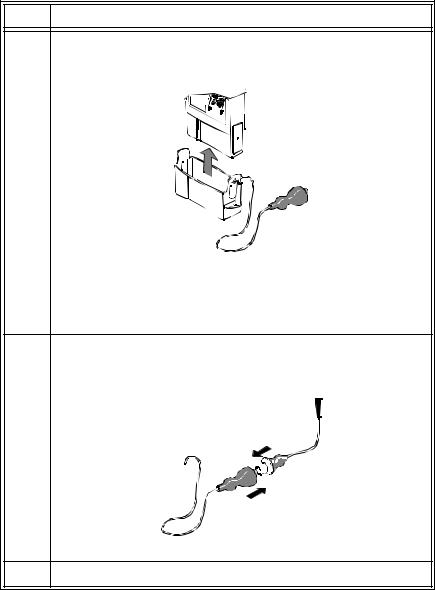
Connecting to the Battery Extender
To use a transmitter in battery-save mode, connect the transmitter to the battery extender in the following steps:
Step Action
1Align the grooves on the transmitter battery door and battery extender cradle. Slip the cradle onto the base of the transmitter, and press until you hear a click.
Note—For accurate functioning, the battery cover must remain closed when the extender is in use. In addition, Philips Medical Systems recommends that the battery remain in the transmitter while the extender is in use.
2Connect the aqua connector between the cradle wire and the power cable. Be sure the connection is secure; the yellow band of the connector should be completely covered.
3Insert the power module into a wall power source.
1-10 Introduction to the Philips Telemetry System

Transmitters
Disconnecting from the Battery Extender
To disconnect the transmitter from the battery extender for ambulatory monitoring, perform the following steps:
Step Action
1Disconnect the aqua connector between the cradle wire and the power cable.
Note—The connector is designed to come apart on its own if the patient gets up without disconnecting the connector.
2Tuck the loose end of the cradle wire into the pouch.
 Warning
DO NOT UNPLUG THE POWER MODULE BEFORE REMOVING THE CRADLE OR DISCONNECTING THE AQUA CONNECTOR.
If you unplug the power module before you disconnect the aqua connector (or remove the cradle):
-The transmitter may reset automatically before switching to battery power, making data unavailable at the Philips Information Center for a brief interval.
-Or, the transmitter may stop sending signals, and a NO SIGNAL INOP will be displayed at the Philips Information Center. In this case, restart monitoring manually by removing and reinserting the transmitter
battery.
Introduction System 1
Introduction to the Philips Telemetry System 1-11

Transmitters
Transmitter
Features
Transmitter The transmitter has a transmitter button (see page 1-7). Depending on how it is Button configured, pressing this button produces:
•A “Nurse Call” message and tone
•A “Nurse Call” message and tone, plus a delayed recording
•A delayed recording
•No response at the Philips Information Center.
Note—Delayed recordings generated by the transmitter button are stored in
Alarm Review.
If desired, you can turn the transmitter button off for individual patients at the Philips Information Center by using the Telemetry Setup Window. See “Turning the Transmitter Button On/Off” on page 2-8 for additional information.
The transmitter button can also be used to initiate an SpO2 measurement. See “Making SpO2 Measurements” on page 4-6 for more information.
Water The transmitters and the battery extender (except the power module) can Resistance withstand submersion in water for 5 minutes and exposure in a shower for 10
minutes. If the battery compartment gets wet, remove the battery and wipe the compartment dry before monitoring. See “Chapter 5. Telemetry System Cleaning” for details.
Caution
Disconnect the battery extender cradle from the power module prior to a patient’s showering.
Earlier Philips transmitters are also resistant to water. If either transmitter is exposed to liquids, remove the battery and dry the battery compartment thoroughly before monitoring.
If the transmitter or battery extender needs cleaning, follow the instructions in “Cleaning the Transmitter & Battery Extender” on page 5-4.
1-12 Introduction to the Philips Telemetry System

Transmitters
Pouch Use During normal use, the transmitter should be worn over clothing, in a pocket, or preferably in a pouch.
 Warning
Place the transmitter in a pouch or over clothing, or both, during patient use. The transmitter should not touch the patient’s skin during normal use.
Introduction System 1
Automatic A service feature of the transmitter is RF Automatic Shutoff, which causes the Shutoff transmitter to stop broadcasting a radio signal if there is no ECG signal for 10
minutes. This prevents interference with other transmitters in use. The INOP message at central is TRANSMITTER OFF. To restart monitoring, attach leads to the patient. Automatic Shutoff can be configured off. When configured off, batteries must be removed and the battery extender should be disconnected when the transmitters are not in use to prevent RF interference and unnecessary battery drain.
Battery |
The Philips Transmitter battery compartment is capable of accommodating any |
Information |
type of standard 9 volt battery. An 8.4 volt Zinc-Air battery can be used with the |
|
both the EASI ECG and standard ECG-only version of the transmitter. The |
|
transmitter was not designed for use with rechargable batteries. |
|
The battery compartment is located at the bottom of the transmitter. The length |
|
of time the battery lasts depends on: |
•The type of transmitter.
•The battery.
•The parameters being monitored - ECG only, ECG and continuous SpO2, or ECG and intermittent SpO2.
When battery power is running low, the INOP message BATTERY WEAK appears in the patient sector to indicate there is at least 15 minutes of battery life remaining.
When there is no battery life remaining, the INOP message REPLACE
BATTERY is displayed.
Introduction to the Philips Telemetry System 1-13

Transmitters
Note—If the BATTERY WEAK message appears when you are making a STAT SpO2 measurement, or changing the SpO2 sample rate out of Manual, it may be necessary to replace the battery immediately in order to continue monitoring.
Be careful not to short circuit the battery. Short circuiting is caused when a piece of metal touches both buttons (positive and negative terminals) at the top of the battery simultaneously (for example, carrying batteries in a pocket with loose change). More than a momentary short circuit will generally reduce the battery life.
Warning
Certain failure conditions, such as extended short circuiting, can cause a battery to overheat during normal use. High temperatures can cause burns to the patient and/or user, or cause the battery to flame. If the transmitter becomes hot to the touch, place it aside until it cools. Then remove the battery and discard it. It’s a good idea to place a piece of tape across the contacts of the battery to prevent inadvertent shorting. Have transmitter operation checked by service to identify the cause of overheating.
The battery should be removed when the transmitter is stored.
Warning
Batteries should be removed from the transmitter at the end of the battery’s useful life to prevent leakage.
Warning
If battery leakage should occur, use caution in removing the battery. Avoid contact with skin. Clean the battery compartment according to instructions in “Chapter 5. Telemetry System Cleaning”.
1-14 Introduction to the Philips Telemetry System
Loading...