


 Loading...
M1026A Anesthetic Gas Module
Service Guide
Anesthetic Gas Module
M1026A
Patient Monitoring
Part Number M1026-9101A
*M1026-9101A*
S PHI

Table of Contents
Introduction 5
Description 5
Product Structure 5
Physical Specifications 5
Environmental Specifications 6
Performance Specifications 6
CO2 Measurement 7
AWRR derived from CO2 Waveform 7
N2O Measurement 7
O2 Measurement 7
Anesthetic Agent Measurement 7
Alarm Ranges 8
Alarm Delay 8
Apnea Alarm 8
INOP Alarms 8
General Measurement Principles 9
Theory of Operation 9
Main PC Board 10
Power Supply 11
Pneumatic System 11
Pump 12
Watertrap 12
Sample Flow Through the Pneumatic Path 13
Agent Identification Assembly 13
Measurement Principle 14
O2 Sensor 14
Specifications 14
Measurement Principle 14
Infrared Measurement Assembly 15
Installation and Patient Safety 16
Physical Installation 16
Environment 17
Label Sheet 17
Making Connections to the AGM 17
Sample Gas Connections to the Gas Exhaust 18
Returning the Gas Sample 18
Setting Up the Gas Return 19
Removing the Gas Sample 20
Setup and Configuration Procedures 20
Altitude Configuration 20
3

Connect Sample Input Tubing 20
Preventive Maintenance (PM) Tasks 20 Post-Installation Checks 21
Safety Requirements Compliance and Considerations 21
Explanation of Symbols Used 21
Power Supply Requirements 22 Grounding the System 22 Equipotential Grounding 23 Combining Equipment 23
Checking and Calibrating the Anesthetic Gas Module 23
Access Service Functions of the M1026A Anesthetic Gas Module 23 When and how to check the Philips M1026A Anesthetic Gas Module 25 Equipment required for checking 25
Checks and adjustments 26
Performance Leakage Check 26 Performance Diagnostic Check 27 Performance Flowrate Check 27
Total Flowrate Check and Adjustment in Purge Mode 27
Measurement Path Flowrate Check and Adjustment 28 Total Flowrate Check in Normal Mode 30
Zero Calibration 30
Barometric Pressure Check and Calibration 31 Span Calibration Check 32
Disposal of Empty Calibration Gas Cylinder 34
Maintaining the Anesthetic Gas Module 35
Preventive Maintenance (PM) Tasks 35
Cleaning 36
Replace PM Parts 36
Internal Nafion Tubing with Bacterial Filters and manifold Seals 36
Room-Air Filter 38 Pump Filter 39 Performance Checks 40
Other factors to maximize uptime or reduce cost of ownership: 40
Troubleshooting the Anesthetic Gas Module 40
Compatibility Criteria for the AGM and the IntelliVue Monitors 40 Flow Charts for Communication and Measurement Type Problems 40 Hardware Related Troubleshooting Strategy 45
INOPs 46 Calibration Checks 48
Calibration Checks Troubleshooting Table 49
Diagnostic Checks 50
Problem Solving Hierarchy 51
Pneumatic System Diagnostic Checks 52
O2 Assembly Diagnostic Checks 52
Optical Path Disgnostic Checks 55
4

IR Measurement Assembly Diagnostic Checks 56 Agent ID Assmebly Diagnostic Checks 57 Power Supply Diagnostic Checks 58
Operating Temperature Diagnostic Checks 59
Test Points, Connectors and Jumpers 59
Test Points 59
Connectors 60
Jumpers 60
Repairing the Anesthetic Gas Module 62
Introduction 62
The Top Cover 64
Removal 64
Replacement 64
Lifting the IR Measurement Mounting Bracket 66
Removal 67
Replacement 67
Infrared Measurement Assembly Head 69
Transferring NVRAM Data to a Replacement Head 69
Sample Cell 73
Removal 73
Replacement 73
Solenoid Valve #1 77
Removal 77
Replacement 77
Power Supply Unit 79
Removal 79
Replacement 79
Main PC Board 80
Removal 80
Replacement 81
O2 Sensor 82
Removal 82
Replacement 83
Agent Identification Head 85
Removal 85
Replacement 86
Pump 87
Removal 87
Replacement 87
Fan 88
Removal 88
Replacement 88
Solenoid Valve #2 90
Removal 90
Replacement 90
5

Top Cover PC Board 91
Removal 91
Replacement 91
Watertrap Manifold and Protector 93
Removal 93
Replacement 93
Power Fuses 94
Removal 94 Replacement 94
Test and Inspection Matrix 94 When to Perform Test Blocks 98 Safety Test Appendix 99
Parts List 101
Calibration Equipment 106
6

1
Anesthetic Gas Module
Introduction
This chapter contains the following information on the M1026A Anesthesia Gas Module:
•A description of the Module, including its physical, environmental and performance specifications
•A general explanation of the measurement principles that the Module uses to measure gas concentrations
•The theory of operation of the Module: the layout of its components and how they work.
Description
The Philips M1026A Anesthetic Gas Module works together with the IntelliVue MP90 patient monitors through an RS232 serial interface. It measures the airway gases of ventilated patients who are under general gas anesthesia, or emerging from it.
The module produces graphical wave data, and inspired and end-tidal numeric data for the following gases:
•CO2
•N2O
•One volatile anesthetic agent
•O2 (optional)
It also generates numerics for the patient’s airway respiration rate (AWRR).
The Agent Identification feature identifies which anesthetic agent is being used.
Product Structure
The only version of the M1026A Anesthetic Gas Module compatible with the IntelliVue Monitoring System is:
M1026A #A05: M1026A Watertrap with 5-Agent-ID (Hal, Iso, Enf, Des, Sev)
• #C03 (MUST-Option): adds fast O2 measurement
Physical Specifications
Size (H x W x D)
90mm x 370mm x 467mm (3.54 x 14.6 x 18.4 in).
5

1 Anesthetic Gas Module |
Introduction |
Weight
8.2 kg (18 lb).
Environmental Specifications
Operating Temperature 15 to 40°C (59 to 104°F). Storage Temperature
-40 to 65°C (-40 to 149°F). Humidity Limit (Operating)
up to 95% RH max @ 40 °C (104 °F). non-condensing
Humidity Limit (Storage)
up to 95% RH max @ 65 °C (149 °F). non-condensing
Altitude Range (Operating)
-305 to 3048m (-1,000 to 10,000 ft). Altitude Range (Storage)
-305 to 5,486m (-1,000 to 18,000 ft). Warm-up Time
After switching on: 2 minutes to measure, 8 minutes for full specification accuracy.
Performance Specifications
All Performance and accuracy specifications are valid based on gas sample tubing M1658A, including watertrap M1657B, and airway adapter 13902A.
Humidity Correction: For CO2 the humidity correction can be set to “wet” or “dry”.
Wet: p [mmHg] = c [Vol%] * (p_abs - p_H2O)/100
Dry: p [mmHg] = c [Vol%] * p_abs /100
Where p = partial pressure, c = gas concentration, p_abs = pressure in breathing circuit, p_H2O = 47 mmHg, partial pressure of water vapor of exhaled gas (37 oC, 100% rh).
For all other gases the readings are always given as dry values.
Sample Flow Rate: 150 ml/min.
Sample Delay Time: All measurements and alarms are subject to a delay of 3 seconds.
Total System Response Time = the sum of the delay time and the rise time.
6

Introduction |
1 Anesthetic Gas Module |
CO2 Measurement |
|
Range: |
0 to 76 mmHg |
Accuracy: |
1.5 mmHg (0 - 40 mmHg) |
|
2.5 mmHg (40 - 60 mmHg) |
|
4.0 mmHg (60 - 76 mmHg) |
Resolution: |
1 mmHg |
Rise-time: |
410 msec typical |
The total system response time is the sum of the sample delay time (3 seconds) and the rise time (410 msec typical)
AWRR derived from CO2 Waveform
Range: |
0 to 60 rpm |
Accuracy: |
± 2 rpm |
Resolution: |
1 rpm |
Detection Criteria: |
6 mmHg variation in CO2 |
N2O Measurement |
|
Range: |
0 to 85 vol% |
Accuracy: |
1.5 vol% + 5% relative |
Resolution: |
1 vol% |
Rise-time: |
510 msec typical |
O2 Measurement |
|
Range: |
0 to 100vol% |
Accuracy: |
± 2.5 vol% or 5% relative, whichever is the greater. |
Resolution: |
1 vol% |
Rise-time: |
450 msec typical |
Anesthetic Agent Measurement
Agent |
Range (vol%) |
Accuracy |
Resolution |
Rise Time |
|
|
|
|
|
Halothane |
0 - 7.5 |
0.2 vol% + 4.0% relative |
0.05 |
< 740 |
Enflurane |
0 - 7.5 |
0.1 vol% + 4.0% relative |
0.05 |
< 620 |
|
|
|
|
|
7

1 Anesthetic Gas Module |
Introduction |
Agent |
Range (vol%) |
Accuracy |
Resolution |
Rise Time |
|
|
|
|
|
|
|
Isoflurane |
0 |
- 7.5 |
0.1 vol% + 4.0% relative |
0.05 |
< 610 |
Sevoflurane |
0 |
- 9.0 |
0.1 vol% + 4.0% relative |
0.05 |
< 570 |
Desflurane |
0 |
- 20.0 |
0.1 vol% + 6.0% relative |
0.05(0-10) |
< 540 |
|
|
|
|
0.1 (10.1-20) |
|
|
|
|
|
|
|
Alarm Ranges
Agent |
|
High Range |
|
Low Range |
|
|
|
||
AWRR |
10 - 60 rpm |
0 - 59 rpm |
||
ETCO2 |
20 - 76 mmHg |
10 - 75 mmHg |
||
IMCO2 |
2 - 20 mmHg |
none |
||
inN2O |
0 - 82 vol% |
none |
||
inO2 |
19-100 vol% |
18 - 99 vol% |
||
et SEV |
0.1 |
- 9.0 vol% |
0.0 |
- 8.9 vol% |
in SEV |
0.1 |
- 9.0 vol% |
0.0 |
- 8.9 vol% |
et DES |
0.2 |
- 20.0 vol% |
0.0 |
- 19.8 vol% |
in DES |
0.2 |
- 20.0 vol% |
0.0 |
- 19.8 vol% |
Halothane, Enflurane, |
Isoflurane |
|
|
|
et |
0.1 |
- 7.5 vol% |
0.0 |
- 7.4 vol% |
in |
0.1 |
- 7.5 vol% |
0.0 |
- 7.4 vol% |
|
|
|
|
|
Alarm Delay
10 seconds if no automatic zero calibration occurs within that time.
Apnea Alarm
Delay Range: |
10 - 40 seconds |
Criterion |
No detected breath within the adjusted delay time |
Alarm: |
Within 2 seconds after this criterion is met, if no automatic zero |
|
occurs |
INOP Alarms
INOP alarms are triggered if:
•The Philips M1026A Anesthetic Gas Module is disconnected or switched off.
•The equipment malfunctions.
•The Agent-ID malfunctions.
•Zero calibration has failed.
8
Introduction |
1 Anesthetic Gas Module |
•Zero calibration is in progress.
•The gas sample tube is occluded, or the water trap is full.
•The Philips M1026A Anesthetic Gas Module is unable to measure.
•Gas contaminant is detected.
•Agent mixture detected.
•Anesthetic agent detected but not selected.
•The module is in warm-up mode.
•No breath detected.
•The Anesthetic Gas Module is incompatible with the monitor
General Measurement Principles
The Philips M1026A Anesthetic Gas Module uses a technique called Non-Dispersive Infrared Gas Concentration Measurement (NDIR) to measure the concentration of gases.
This works as follows:
•The gases that the Philips M1026A Anesthetic Gas Module can measure absorb infrared (IR) light.
•Each gas has its own absorption characteristic. The gas mixture is transported into a sample cell, and an IR filter selects a specific band of IR light to pass through the gas. For multiple gas measurements, multiple IR filters are used.
•The higher the concentration of gas in the mixture the more IR light it absorbs. This means that higher concentrations of IR absorbing gas results in lower transmission of IR light.
•The amount of IR light transmitted through an IR absorbing gas is measured.
•From the amount of IR light transmitted, the concentration of gas can be calculated. This calculation provides the gas concentration value.
O2 gas cannot be measured with this technique as it does not absorb IR light. Hence O2 gas is measured with a sensor that makes use of the paramagnetic properties of O2 for its fast measurement technique.
Theory of Operation
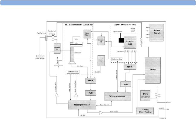
Figure 1 shows the functional blocks within the Philips M1026A Anesthetic Gas Module.
9
1 Anesthetic Gas Module |
Introduction |
Figure 1 Anesthetic Gas Module Functional Block Diagram
The main components of the Philips M1026A Anesthetic Gas Module are:
•Main PC Board.
•Switching Power Supply.
•Pneumatic System.
•Agent Identification.
•O2 Sensor.
•Infrared Measurement Assembly.
Main PC Board
This digital board:
•Controls the pneumatic system and the IR measurement assembly.
•Converts the preamplified analog output signal from the IR detector into a digital value. Under
software-controlled processing, this is then converted to a fully compensated gas concentration value.
•Converts analog signals from the sample cell pressure sensor, transducer, sample cell temperature thermistor, and the ambient temperature thermistor, into digital environmental data for gas compensation and data reporting.
•Converts an analog O2 signal, supplied by the O2 measurement system, into O2 concentration data for CO2 compensation and O2 data reporting.
10
Introduction |
1 Anesthetic Gas Module |
•Converts analog signals from the flow-control servo system and power supply into digital data for status reporting.
•Processes the algorithm for end-tidal, inspired and respiration rate values.
•Controls the communication between the monitor and the Philips M1026A Anesthetic Gas Module through an RS232 interface that uses a standard communications protocol.
•Contains the software program that controls the Philips M1026A Anesthetic Gas Module in a 128K EPROM.
Power Supply
The input voltage is 100V - 240V. The output voltages are ±12V and +5V and the maximum output is 55W.
Pneumatic System
The main parts of the pneumatic system are:
•Watertrap.
•Pump assembly, including pump outlet filter.
•Two solenoid valves.
•Tubing system including:
–Differential pressure transducer and restrictor for control of the total flow.
–Measurement path.
–Drainage path parallel to measurement path.
•Ambient air reference filter.
Figure 2 Pneumatic System
11
1 Anesthetic Gas Module |
Introduction |
The pneumatic system works in the following way:
1Eliminates residual water and fluids from patient sample gas using the watertrap and eliminates water vapor using Nafion Tubing.
2Splits the patient’s sample gas flow (150ml/min) into the measurement path (120ml/min) and drainage path (30ml/min).
3Passes the patient’s sample gas in the measurement path at 120ml/min through the measurement benches.
4Delivers zero calibration gas to the sample cells for the periodic zeroing.
5Exhausts the patient’s sample gas, the zero calibration gas, and the span calibration gas.
6Monitors for an occlusion in the sampling pneumatics.
Pump
The servo-controlled pump is attached to the exhaust of the Anesthetic Gas Module. It generates the flow through the system and pulls the gas from the airway adapter through the measurement subsystems to the exhaust outlet. It also delivers the zero calibration gas to the sample cells of the measurement subsystems for the periodic zero procedures and it exhausts the patient’s sample gas, the zero calibration and field calibration gases.
The flow-rate control logic drives the pump as hard as necessary to maintain the selected flow rate. A partial occlusion or an inefficient pump results in the pump being driven harder. A serious occlusion results in the pump being driven at or near its maximum load. This triggers a sensing circuit, which then reports an occlusion.
Watertrap
Water Separation Filters
Water Fuses
Patient Sample Inlet
Water Reservoir
Figure 3 Watertrap
12

Introduction |
1 Anesthetic Gas Module |
The watertrap consists of two water separation filters, two water fuses and a water reservoir. The gas sample coming from the patient may contain fluids which are separated from the gas at the first water separation filter. The gas is then split into two paths, the “measurement” path with the main part of the total gas flow (including water vapor) continuing on the “dry” side of the separation filter and the “drainage” path (containing any liquid droplets) with the smaller amount of the total flow continuing on the “wet” side of this filter. At the pump both gas paths are recombined.
The watertrap proper includes “water fuses” in both the “measurement” and the “drainage” paths, consisting of a material that swells when getting wet (when the reservoir is full or when fluid penetrates the separation filter and enters the “measurement” path) and blocks the respective path at the inlet of the unit. Once the “water fuses” are blown, any passage of fluid is blocked and the gas flow resistance increases so that an occlusion is detected.
Sample Flow Through the Pneumatic Path
•The drainage path serves to withdraw fluid separated from the gas sample into the watertrap reservoir, so that the AGM interior is protected from fluid that might cause an occlusion in the measurement path.The drainage path leads into the large watertrap reservoir where all liquid water and other fluids are collected. When the drainage path leaves the watertrap through a water separation filter and a through a water fuse it leads through internal Nafion tubing then through a bacterial protection filter and flow restrictor directly to the pump. This flow restrictor determines the percentage distribution between drainage and measurement path flow.
•The measurement path leads through a water separation filter and through a water fuse on into the measurement system. The patient sample gas (on the measurement path) then flows through internal Nafion tubing and through a bacterial protection filter to the first solenoid valve. Room air for the zero calibration is alternatively input (via a dust filter) to this solenoid valve. The solenoid valve switches between the two gases depending on the current mode of operation - normal measurement or zero calibration.
The patient sample gas or zero calibration gas then flows through the measurement subassemblies:
•the IR Measurement Assembly (for measurement of anesthetic agent, CO2 and N2O)
•the O2 cell (if present)
•the Agent Identification assembly.
A second solenoid valve between the O2 cell and the Agent Identification Assembly routes room air directly to the Agent Identification Assembly for optimal purging of the assembly during zero
calibration.
From the Agent Identification Assembly the patient sample gas or zero calibration gas flows to the pump. Before reaching the pump, it joins the drainage path again.
From here it is passed through a filter and damper to the flow sensor which consists of a differential pressure transducer and a flow restrictor. The flow sensor determines, stabilizes and limits the flow rate of the sampled gas.
After the gas has passed through the flow sensor it is routed through a second damper to the Sample Gas output.
Agent Identification Assembly
The agent ID analyzer identifies which anesthetic agents are present in a gas sample drawn from the patients’s airway. The anesthetic agents are identified from a set of known anesthetic gases.
13

1 Anesthetic Gas Module |
Introduction |
Isoflurane
Enflurane
Halothane
Sevoflurane
Desflurane
Measurement Principle
Sample gas passes through the agent identification head where the absorption characteristics of the gas are measured. This is done using NDIR technology as described in General Measurement Principles. The head outputs analog signals and sends them for processing to identify the anesthetic agent.
Data averaging is used to ensure accurate measurements when agent concentrations are low. The information used to calculate the concentrations of the three agents includes:
•The preamplified outputs from the IR detector.
•The thermistor output from the agent identification head.
•Zero calibration constants.
O2 Sensor
Specifications
Weight |
335 g (0.75 lbs) |
Size (HxWxD) |
54 x 54 x 56 mm |
Calibration |
Zero: Room Air |
|
Span: Suitable calibrated mixture |
Measurement Principle
The O2 sensor uses a fast O2 measurement technique that utilizes O2 paramagnetic properties.
Two sealed spheres forming a dumb-bell assembly are filled with N2. The dumb-bell assembly is suspended in a symmetrical non-uniform magnetic field. The spheres take up a position away from the most intense part of the field, due to the diamagnetic force on the dumbbells. The dumb-bell assembly is then surrounded by the sample gas.
When the surrounding sample gas contains O2, the dumb-bell spheres are forced even further out of the magnetic field by the relatively stronger paramagnetic O2 gas. The torque acting on the dumb-bell is proportional to the paramagnetism of the surrounding gases, and can therefore be taken as a measure of the oxygen concentration.
This torque is measured by monitoring the current required in a servo system that attempts to return the dumb-bells to their normal position.
14
Introduction |
1 Anesthetic Gas Module |
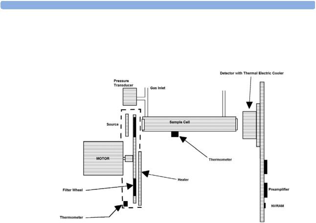
Infrared Measurement Assembly
The measurement assembly measures the IR light absorption of the gases in its sample cell (see Figure 4).
Figure 4 Anesthetic Gas Module Measurement Assembly
The measurement assembly contains the following subassemblies:
IR Source: |
The ceramic IR source is heated to 600°C by applying a constant |
|
drive voltage across it. |
Filter Wheel Assembly: |
The filter wheel assembly includes IR filters for the anesthetic agent, |
|
CO2, N2O and a reference channel. A blank segment (dark period) |
|
marks the beginning and end of the filter series. |
Sample Cell: |
The sample cell is a stainless steel tube. It has non-IR absorbing |
|
sapphire windows at both ends, and barbed inlet and outlet ports. |
|
The inlet and outlet ports are placed as close as possible to the |
|
windows so that the gas flows effectively through the cell. |
Preamp Assembly |
The preamplifier board assembly includes an IR detector, an IR- |
|
detector thermistor, a TE cooler, and a pre-amplification circuit. The |
|
output from the preamplifier is a stream of pulses; this pulse train has |
|
one pulse for each IR filter, and is terminated by a blank period (dark |
|
level phase) (see Figure 5). |
15

1 Anesthetic Gas Module |
Installation and Patient Safety |
Figure 5 IR Detector Output Signal
Installation and Patient Safety
This chapter describes how to install the Philips M1026A Anesthetic Gas Module. It details the operating environment required by the Philips M1026A Anesthetic Gas Module as well as instructions on how to affix the local language labels and physically connect it to the monitor. Next, the patient safety information is detailed. Finally, this chapter describes the software setup required and any postinstallation checks that have to be performed before using the Philips M1026A Anesthetic Gas Module together with a reminder of the preventive maintenance (PM) checks and their frequencies.
Where post-installation procedures are specific to installation, they are described in full in this chapter. For procedures which are also used in other situations (for example calibration, preventative maintenance, etc.), a reference to the description will be given.
Physical Installation
This section describes the operating and storage environment for the Philips M1026A Anesthetic Gas Module, affixing the local-language labels, connecting to the monitor, and fitting the gas exhaust return system.
CAUTION The Philips M1026A Anesthetic Gas Module must be positioned horizontally on a level surface. To avoid condensed water collecting in the patient sample tube, it is recommended that the Philips M1026A Anesthetic Gas Module is positioned at or above patient level, wherever possible.
16
Installation and Patient Safety |
1 Anesthetic Gas Module |
Environment
WARNING Possible explosion hazard if used in the presence of flammable anesthetics.
The environment where the Philips M1026A Anesthetic Gas Module is used should be free from vibration, dust, corrosive or explosive gases, and extremes of temperature and humidity.
For a cabinet mounted installation with the monitor, allow sufficient room at the front for operation and sufficient room at the rear for servicing with the cabinet access door open.
The Philips M1026A Anesthetic Gas Module operates within specifications at ambient temperatures between 15°C and 40°C, 8 minutes after switching it on.
Ambient temperatures that exceed these limits could affect the accuracy of this instrument and cause damage to the components and circuits. Allow at least 2 inches (5cm) clearance around the instruments for proper air circulation.
CAUTION If the Philips M1026A Anesthetic Gas Module has been stored at temperatures below freezing, it needs a minimum of 4 hours at room temperature to warm up before any connections are made to it.
Make sure that the Philips M1026A Anesthetic Gas Module is free of condensation before operation. Condensation can form when equipment is moved from one building to another, thus being exposed to moisture and differences in temperature.
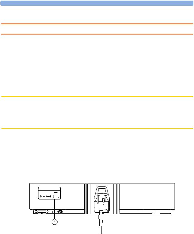
Label Sheet
There is a label sheet included with the Philips M1026A Anesthetic Gas Module which has the translated versions for “Airway Gases”. You can stick a translated version over “Airway Gases” on the left of the front panel. See (1) in Figure 6.
PADM1026A


Figure 6 Label for the Philips M1026A Anesthetic Gas Module
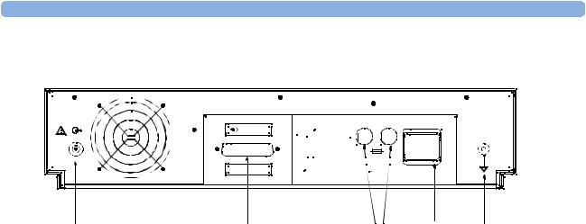
Making Connections to the AGM
All connections to the AGM are made on its rear panel. Refer to Figure 7.
17
1 Anesthetic Gas Module |
Installation and Patient Safety |
MONITOR |
600VA max. |
|
|
|
T1.6 H 250V |
RS 232 |
100-240V |
|
50-60 Hz |
brear2d.tif |
|
(6) |
(2) |
(5) |
(1) |
(4) |
Gas |
RS232 |
Fuses |
Local |
Equipotential |
Outlet |
Connector |
|
Power |
Grounding |
|
|
|
Connector |
Terminal |
Figure 7 The Rear Panel
1Local power connector; this is a 3-pin connector, used to connect the AGM to the local line voltage supply.
The module can be operated from an ac power source of 100 - 240 V ± 10%, 50/60 Hz. The adjustment is made automatically by the power supply inside the module.
2RS232 Connector (RS232 Interface); this is a 25-pin “D” type connector, used to connect the AGM to the RJ45 connector of the monitor (Slot 08a, 07a, 04a, 03a, or 02a, - MIB I/O port - see
Connection of Devices via the MIB/RS232 Interface in the Installation Instructions section).
The connection can be made with the following cables:
–M1026A#K11 1 m (M1026-61001)
–M1026A#K12 3 m (M1026-61002)
–M1026A#K13 10 m (M1026-61003)
3Equipotential Grounding Terminal; this is used to connect the AGM to the hospital’s grounding system.
4Line protection fuses, T1.6 H 250V.
5Anesthetic gas exhaust. If N2O and/or other inhalation anesthetics are used during anesthesia, pollution of the operating room should be prevented. Once the gas sample has passed through the
AGM, it should either be returned to or removed from the anesthesia circuit.
Sample Gas Connections to the Gas Exhaust
Returning the Gas Sample
You will need the following equipment to return the gas sample to the anesthesia circuit:
18
Installation and Patient Safety |
1 Anesthetic Gas Module |
Equipment |
Part Number |
Comments |
|
|
|
Gas Exhaust Return Line |
M1655A |
Tubing includes two parts: |
|
|
Tube A = 50cm long |
|
|
Tube B = 3m long |
Gas Exhaust Return Filter |
M1656A |
Single patient use only |
|
|
|
NOTE The M1655A may not be available in all countries.
Setting Up the Gas Return
(see diagram Figure 8)
1Fit the male luer lock connection (2) of the shorter tube, to the female side of the M1656A Gas Exhaust Return Filter.
2Fit the female luer lock connection (3) of the longer tube, to the male side of the M1656A Gas Exhaust Return Filter.
3Fit the open end (7) of the longer tube to the AGM’s Anesthetic Gas Exhaust.
4Fit the open end (5) of the shorter tube to the ventilation circuit.
Figure 8 Setting Up the Gas Return
1 M1656A Gas Exhaust Return Filter
M1655A Gas Exhaust Return Line comprising:
2Female luer lock
3Male luer lock
19

1 Anesthetic Gas Module |
Installation and Patient Safety |
4Dampener
5Shorter tube
6Connecting tube
7Longer tube - connected to AGM exhaust port
Removing the Gas Sample
To remove the gas sample from the anesthesia circuit, a scavenging system needs to be connected to the AGM’s Anesthetic Gas Exhaust. If you intend to use a scavenging system with the AGM, one of the following parts must also be connected to protect it against malfunction:
1A ventilator reservoir where the suction pressure does not exceed 0.3-0.4 mmHg or
2A scavenging interface, properly set and maintained (see scavenging interface manufacturer’s instructions).
Setup and Configuration Procedures
This section describes final setting up and configuration procedures that must be completed after the AGM is connected to the monitor and switched on but before the AGM is used for monitoring.
Altitude Configuration
The altitude setting for the monitor is important as it is used as a reference to check the AGM ambient pressure measurement.
See the Installation Instructions section for details.
Connect Sample Input Tubing
Connect the sample input tubing to the watertrap at the patient sample inlet on the water separation filter. For details, refer to the Instructions for Use.
Preventive Maintenance (PM) Tasks
The preventive maintenance (PM) tasks are described in detail in chapter 5 of this guide. Here is a short list of the PM tasks and how often they must be performed.
To ensure operation of the Philips M1026A Anesthetic Gas Module within specified limits:
1Check the ventilator fan in the AGM for proper operation and build-up of dust and lint every 6 months.
2Check the AGM’s calibration at least once every 12 months, or whenever the validity of the readings is in doubt.
3Replace the internal Nafion; tubing, room air filter, and pump filter, internal bacterial filters and watertrap manifold seals, using the PM kit, every 12 months.
4Test the pump using the test procedure provided in the PM Kit every 12 months. The squareshaped pump should be cleaned before testing; the round-shaped pump may not be cleaned.
5Check electrical safety (ground impedance test and enclosure leakage current test) at least every 12 months.
All safety and maintenance checks must be made by qualified service personnel.
20
Installation and Patient Safety |
1 Anesthetic Gas Module |
WARNING Failure to implement a satisfactory maintenance schedule by the individual, hospital or institution responsible for the operation of this equipment may cause equipment failure and possible health hazards.
Post-Installation Checks
See Test and Inspection Matrix for details.
WARNING Do not use the instrument for any monitoring procedure on a patient if you identify anything which indicates impaired functioning of the instrument.
Safety Requirements Compliance and Considerations
The Philips M1026A Anesthetic Gas Module complies with the following international safety requirements for medical electrical equipment:
•UL 2601-1
•IEC-60601-1
•CSA C22.2 No. 601.1-M90
•EN 60601-1
•EN 60601-1-2
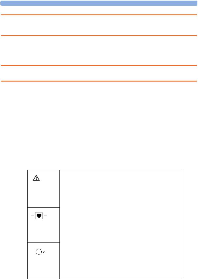
Explanation of Symbols Used
Attention, consult accompanying documents.
Indicates that the instrument is type CF and is designed to have special protection against electric shocks (particularly regarding allowable leakage currents, having an F-Type isolated (Floating) applied part), and is defibrillator proof.
A gas output (this symbol is also used to indicate an electrical output on the monitor).
21
1 Anesthetic Gas Module |
Installation and Patient Safety |
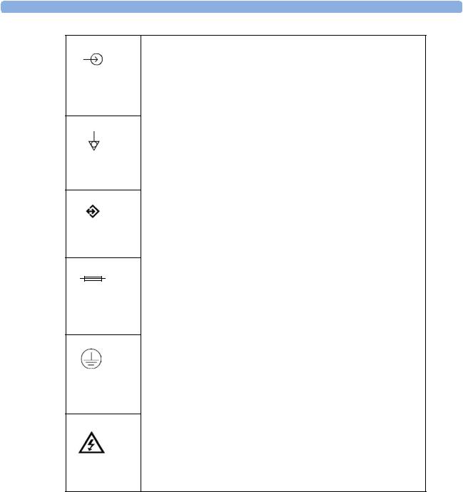
A gas input (on the monitor this symbol can also stand for a video or 60V dc input).
Equipotential grounding terminal.
RS232 communication port.
Fuse.
Protective earth ground.
Electrical shock hazard.
The Anesthetic Gas Module is protected against the effects of defibrillation and electrosurgery.
Power Supply Requirements
The system and the Anesthetic Gas Module can both be operated from an AC supply of 100 - 240V ±10%, 50 - 60Hz.
Grounding the System
To protect the patient and hospital personnel, the cabinet of the installed equipment has to be grounded. The equipment is supplied with a detachable 3-wire cable which grounds the instrument to the power line ground (protective earth) when plugged into an appropriate 3-wire receptacle. If a 3- wire receptacle is not available, consult the hospital electrician.
22

Checking and Calibrating the Anesthetic Gas Module |
1 Anesthetic Gas Module |
WARNING Do not use a 3-wire to 2-wire adapter.
Equipotential Grounding
Protection class 1 instruments are already included in the protective grounding (protective earth) system of the room by way of grounding contacts in the power plug. For internal examinations on the heart or the brain, Computer Module and Display Module of the System and the Philips M1026A Anesthetic Gas Module must have separate connections to the equipotential grounding system.
One end of the equipotential grounding cable (potential equalization conductor) is connected to the equipotential grounding terminal on the instrument’s rear panel and the other end to one point of the equipotential grounding system. The equipotential grounding system assumes the safety function of the protective grounding conductor if ever there is a break in the protective grounding system.
Examinations in or on the heart (or brain) should only be carried out in rooms designed for medical use incorporating an equipotential grounding system.
Combining Equipment
If it is not evident from the instrument specifications whether a particular instrument combination is hazardous or not, for example, due to summation of leakage currents, the user should consult the manufacturers concerned or an expert in the field, to ensure that the necessary safety of all instruments concerned will not be impaired by the proposed combination.
Checking and Calibrating the Anesthetic Gas
Module
This chapter explains how to check the Anesthetic Gas Module to ensure that it is operating within its specified limits. A list of the equipment required to carry out the checks is included, as well as step-by step instructions for the calibrations.
If you receive fail indications while testing, refer to the troubleshooting section of this chapter for guidance. If you are instructed to remove or replace parts of the Anesthetic Gas Module refer to the respective section.
Access Service Functions of the M1026A Anesthetic Gas Module
Enter service mode and select the service screen (see Testing and Maintenance for instructions on entering service mode). In the Setup Gas Analyzer menu you can choose whether the Gas Analyzer Diagnostic window or the Gas Analyzer Calibration window should be displayed. In this window you can as well start the flow calibration, the barometric pressure calibration and the gas span calibration.
The Setup Gas Analyzer menu can be accessed by either going to the Main Setup menu and selecting Gas Analyzer, or by pressing the setup key on the Anesthetic Gas Module.
23

1 Anesthetic Gas Module |
Checking and Calibrating the Anesthetic Gas Module |
Figure 9 Gas Analyzer Diagnostic Window
This window provides you with diagnostic information about the AGM. In the Setup Gas Analyzer menu select Service Window then select Calibration to access this window.
Figure 10 Gas Analyzer Calibration window
24

Checking and Calibrating the Anesthetic Gas Module |
1 Anesthetic Gas Module |
This window provides you with information about all calibrations that can be performed on the Anesthetic Gas Module. In the Setup Gas Analyzer menu select Service Window then select Diagnostic to access this window.
When and how to check the Philips M1026A Anesthetic Gas Module
To ensure that the Philips M1026A Anesthetic Gas Module operates with the specified limits, it must be checked:
1After installation
2Every 12 months or if the measurements are in doubt.
3After repairing the AGM
If you find values outside the tolerance limits while checking, the Philips M1026A Anesthetic Gas Module must be recalibrated. Tolerance values are given at the end of each section.
The basic steps to check the Philips M1026A Anesthetic Gas Module are:
1Enter Service Mode at the monitor and wait for first automatic zero calibration after the warm-up period.
2Perform:
a.a leakage check
b.a flowrate check
to ensure that there are no leaks in the gas system and that the flowrates are set correctly.
3Perform Zero calibration.
4Check that there are no reported errors.
5Check the Barometric Pressure calibration; perform it if necessary.
6Check the Span calibration of gases; perform it if necessary.
7If Barometric Pressure or Span calibrations were performed, re-perform Zero calibration.
WARNING Only perform Zero, Barometric Pressure and gas Span calibration checks when the top cover is closed. Light and electro-magnetic interference can affect the measurements.
Equipment required for checking
The following equipment is required for checking the AGM. Part numbers are given in the Parts List section.
1Electronic Flowmeter M1026-60144 (Instructions are provided with the flowmeter. See also Service Note M1026A-034).
2Span Calibration Equipment.
–Calibration Gas.
–Calibration Tubing
25

1 Anesthetic Gas Module |
Checking and Calibrating the Anesthetic Gas Module |
WARNING Philips Calibration Gas contains Halocarbon 22. Halocarbon 22 is represented in the Calibration menu by “Substitute”, which is the default. If you are using another calibration gas, this must be selected in the menu.
Checks and adjustments
The following sections explain the steps needed to carry out the checks and adjustments. A complete check and calibration procedure requires approximately 45 minutes, including waiting time.
NOTE Make sure that the watertrap is attached.
Performance Leakage Check
Complete the following steps to do a performance leakage check:
NOTE Do not perform the leakage check while a Zero calibration is running.
1Switch on the Philips M1026A Anesthetic Gas Module and the monitor.
2Wait until the Anesthetic Gas Module enters the warm up phase.
3Connect a flowmeter to the exhaust outlet of the Philips M1026A Anesthetic Gas Module.
4Connect the watertrap to the watertrap manifold.
5Note the flowrate.
6Block the gas inlet at the watertrap inlet connector (use your fingertip).
The reading at the flowmeter should decrease to Zero (see table below). If it does not, systematically block the pneumatic path at various points before the pump to isolate the leakage point. (See Figure 2, "Pneumatic System" for tubing connections.) When the fault has been corrected, repeat the leakage check.
7Connect the flowmeter to the inlet.
8Note the flowrate.
9Block the Anesthetic Gas Module exhaust (using your finger tip).
10Check the effect of blocking the exhaust.
The reading at the flowmeter should decrease to Zero (see Table 4-1). If it does not, systematically block the pneumatic path at various points after the pump to isolate the leakage point. (See Figure 2, "Pneumatic System" for tubing connections.) When the fault has been corrected, repeat the leakage check.
Items |
Value / Tolerance |
|
|
Leakage |
Range: 0 → 4 ml/min |
|
|
26

Checking and Calibrating the Anesthetic Gas Module |
1 Anesthetic Gas Module |
Performance Diagnostic Check
Complete the following to do a performance diagnostic check:
1Enter the service mode of the monitor and let the Philips M1026A Anesthetic Gas Module complete the warm-up phase (the GA WARMUP INOP disapears).
2Make sure that the watertrap is attached.
3In the Setup Gas Analyzer menu select Service Window then select Diagnostic to access the Gas Analyzer Diagnostic window.
4Check that no permanent problems are reported for the Philips M1026A Anesthetic Gas Module in the Gas Analyzer Diagnostic window.
Performance Flowrate Check
Always perform a leakage check before the flowrate check. Three flowrates need to be checked in the following order:
1Total flow in Purge mode.
2Flow in Measurement Path in Normal mode.
3Total flow in Normal mode.
These flowrate checks are described in the following three procedures.
The total flow is measured by connecting the flowmeter to the exhaust, the measurement path flow is measured by connecting the flowmeter to the gas inlet with a special test fixture.
The Flowrate values are summarized in the following table:
Total Flowrate |
Value |
|
|
Purge |
310 ml/min |
Normal |
150 ml/min |
|
|
NOTE Do not perform the flowrate check while a Zero calibration is running.
Total Flowrate Check and Adjustment in Purge Mode
To make the flowrate measurements and any necessary adjustment:
1Enter the service mode of the monitor and let the Philips M1026A Anesthetic Gas Module complete the warm-up phase (the GA WARMUP INOP disapears).
2In the Setup Gas Analyzer menu select Service Window then select Calibration to access the Gas Analyzer Calibration window.
3 Enter the Setup Gas Analyzer menu and select Start Flow Cal.
4Select Flow Rate.
5Select Purge for purge flow (310 ml/min).
6Connect a flowmeter to the exhaust port of the Philips M1026A Anesthetic Gas Module.
27

1 Anesthetic Gas Module |
Checking and Calibrating the Anesthetic Gas Module |
7Note the actual flowrate by following the instructions accompanying the flowmeter. If the actual flowrate is outside the tolerance, it must be adjusted. If no adjustments are required, select Stop Flow Cal.
Total Flowrate in Purge Mode |
Tolerance |
|
|
310 ml/min |
+/- 15 ml/min |
|
|
Flowrate Adjustment:
8Remove the Philips M1026A Anesthetic Gas Module top cover (see “The Top Cover” on page 64)
9Correct the flowrate by adjusting potentiometer R125 on the Main PC board until the required value is achieved.
Flowrate Calibration:
10If you have made adjustments you must save the settings. Therefore select Store Flow Cal and confirm when prompted.
The system then runs through various flowrates and switches the pump off before it saves the values internally.
The flow display in the Calibration window reflects these changes and the status “Flow Cal Stored” appears.
11Disconnect the flowmeter from the exhaust port.
Measurement Path Flowrate Check and Adjustment
The flowrate of the measurement path is checked using a test fixture in the form of a modified watertrap. In order to perform the flow rate check, the following equipment is required:
•Flow Split Test Tool M1026-60136
•Electronic Flowmeter M1026-60144
NOTE 1 Check that the test fixture is still valid for use. It must be less than two years old. The test fixture is labelled with a “Received” date that needs to be filled in when the test fixture is received.
2The flow value that is labelled on the test fixture is to be used to perform the measurement path flowrate check. It is only valid for this test fixture.
3Check the test fixture visually for leaks. Regularly perform a leakage check with the test fixture attached instead of the watertrap. Block both lines (drainage and measurement) at the same time while performing the leakage check. Block the measurement line with a luer cap or a similar device and the drainage line with your fingertip. If a leak exists, replace the test fixture.
WARNING Always handle the test fixture carefully and avoid contact with dust. Do not change or modify the test line/loops as this can change the flow resistance.
Make sure that there are no sharp bends or kinks in the tubing that leads to the test fixture. If a kink is visible, replace the fixture and use the new one.
28
Loading...