


 Loading...
Panasonic
Voice Processing System
Installation Manual
Model No. KX-TVP200
Thank you for purchasing the Panasonic Voice Processing System, Model KX-TVP200.
Please read this manual before installing, customising, or operating the Voice Processing System.

Thank you for purchasing the Panasonic
KX-TVP200 Voice Processing System.
We are confident that it will provide your customer or client with many years of dependable service.
This Voice Processing System was especially tailored for the environment of your country. For example, it can be configured for English, Spanish, or a third language:
System prompts—Recorded by the factory in English User 1 prompts—Record in any language you like User 2 prompts—Recorded by the factory in Spanish
These prompts guide subscribers and non-subscribers through specific VPS operations.
However, we would like to stress that for outside callers who merely need to be guided to an extension, a mailbox, or other destinations (e.g., a fax machine), they can be greeted by a Custom Service. This supports many languages as there are 12 keys on a touchtone phone and you can record up to 100 Custom Service menus. One twelfth of these menus can be recorded in one language if you desire. Another twelfth can be recorded in another language, and so on. Thus callers can be guided entirely in their native languages. For a multi-cultural country, Custom Service is a truly powerful feature. Please see "Custom Service" in Appendix A1 SYSTEM FEATURES for more details.
Notes
•In this manual, there may be PBX model numbers which are not available in your country.
•In this manual, the suffix of each model number is omitted.
•Throughout this manual the term he or she, his or her may be used. In order to improve readability rather than continually use he/she we have only used one of these terms. The term he or she should be taken as being interchangeable.
This product is only for connection behind a suitable PBX and should not be connected directly to the network.
This product complies with the essential requirements of the Directive 1999/5/EC Radio and telecommunications terminal equipment directive.
A copy of the manufacturers declaration of conformity to the essential requirements of the R&TTE directive is available at the following web address: http://doc.panasonic-tc.de
2 Installation Manual

Important Information
SAFETY REQUIREMENTS
•Follow all product warnings, cautions, and instructions.
•Handle the unit carefully. Do not drop or otherwise expose the unit to physical shock.
•If the unit malfunctions, disconnect the unit from the telephone line and check the line by reconnecting the telephone. If the telephone operates properly, have the VPS repaired by a qualified service technician.
•Install the unit so that the power cord is not obstructed in any way. Do not connect this unit to an extension cord.
•Keep the unit free of dust, moisture, condensation, high temperature exposure (more than 40 °C) and vibration. Do not expose the unit to direct sunlight.
•Mount the unit on a stable wall surface. Do not mount the VPS inside of a separate enclosure unless it is properly ventilated.
•Read all the information contained in this manual.
•This unit is designed to operate at one specific voltage and current setting. The proper voltage and current required for this unit are listed on the product label.
•This unit is equipped with a 3-wire earthing plug. The plug will only fit into a earth power outlet. Do not modify this plug in any way. If it cannot be inserted into the outlet, have the outlet replaced by a licensed electrician.
•Unplug and transport the unit to a service technician if the power supply cord is frayed or damaged, if the cabinet is cracked or broken, or when the unit has been exposed to moisture, has been dropped, or is not otherwise operating properly.
•Unplug the unit from its power source before cleaning.
•Do not block the vent slots and openings located on all sides of the unit.
•Do not disassemble this product. Dangerous electrical shock could result. The unit must only be disassembled and repaired by qualified service technicians.
•Do not insert wires, pins, or any other material into the unit’s vent slots or access points. This could result in electrical shock and serious unit malfunction.
•Do not install the unit near water or moisture, heating appliances, or electrical noise generating devices such as televisions, monitors, fluorescent lamps, or electric motors.
•Do not overload wall outlets. Overloaded outlets could result in fire and/or electrical shock.
•Do not use solvents, liquid cleaners, water, or abrasive powders to clean this unit. Use only a damp soft cloth for cleaning.
•Do not use the telephone during a lightning storm or to report a gas leak in the vicinity of the leak.
WARNING
TO PREVENT FIRE OR ELECTRICAL SHOCK, DO NOT EXPOSE THIS UNIT TO RAIN OR MOISTURE.
Installation Manual |
3 |
|
|

The serial number of this product may be found on the label affixed to the bottom of the unit. You should note the serial number of this unit in the space provided and retain this book as a permanent record of your purchase to aid in identification in the event of theft.
MODEL NO.:
SERIAL NO.:
For your future reference
DATE OF PURCHASE
NAME OF DEALER
DEALER’S ADDRESS
DEALER’S TEL. NO.
WARNING
THIS UNIT MAY ONLY BE INSTALLED AND SERVICED BY QUALIFIED SERVICE PERSONNEL.
WHEN A FAILURE OCCURS WHICH RESULTS IN THE INTERNAL PARTS BECOMING ACCESSIBLE, DISCONNECT THE POWER SUPPLY CORD IMMEDIATELY AND RETURN THIS UNIT TO YOUR DEALER.
DISCONNECT THE TELECOM CONNECTION BEFORE DISCONNECTING THE POWER CONNECTION PRIOR TO RELOCATING THE EQUIPMENT, AND RECONNECT THE POWER FIRST.
THIS UNIT IS EQUIPPED WITH AN EARTHING CONTACT PLUG. FOR SAFETY REASONS, THIS PLUG MUST ONLY BE CONNECTED TO AN EARTHING CONTACT SOCKET WHICH HAS BEEN INSTALLED ACCORDING TO REGULATIONS.
THE POWER SUPPLY CORD IS USED AS THE MAINS DISCONNECT DEVICE, ENSURE THAT THE SOCKET-OUTLET IS LOCATED/INSTALLED NEAR THE EQUIPMENT AND IS EASILY ACCESSIBLE.
4 Installation Manual

Note
Before you start setting or changing system parameters, we recommend that you turn off the Answer Mode with the OFLN command. While off, the power LED of the VPS will flash and the VPS will not answer any incoming call. After you finish programming, use the ONLN command to turn on the Answer Mode (normal operation). Please see 7.2.1 Off-line Set (OFLN) and 7.2.2 On-line Set (ONLN) for more details.
Trademarks
•HyperTerminal is either a registered trademark or a trademark of HILGRAEVE, INCORPORATED in the United States and/or other countries.
•IBM is either a registered trademark or a trademark of International Business Machines Corporation in the United States and/or other countries.
•Procomm Plus is either a registered trademark or a trademark of DATASTORM TECHNOLOGIES, INC. in the United States and/or other countries.
•Smartcom is either a registered trademark or a trademark of Hayes Microcomputer Products, Inc. in the United States and/or other countries.
•All other trademarks identified herein are the property of their respective owners.
Installation Manual |
5 |
|
|

Precaution
FOR YOUR SAFETY PLEASE READ THE FOLLOWING TEXT CAREFULLY.
This appliance is supplied with a moulded three pin mains plug for your safety and convenience. A 5 amp fuse is fitted in this plug.
Should the fuse need to be replaced please ensure that the replacement fuse has a rating of 5 amps and that it is approved by ASTA or BSI to BS1362.
Check for the ASTA mark or the BSI mark on the body of the fuse.
If the plug contains a removable fuse cover you must ensure that it is refitted when the fuse is replaced. If you lose the fuse cover the plug must not be used until a replacement cover is obtained.
A replacement fuse cover can be purchased from your local Panasonic Dealer.
IF THE FITTED MOULDED PLUG IS UNSUITABLE FOR THE SOCKET OUTLET IN YOUR HOME THEN THE FUSE SHOULD BE REMOVED AND THE PLUG CUT OFF AND DISPOSED OF SAFELY. THERE IS A DANGER OF SEVERE ELECTRICAL SHOCK IF THE CUT OFF PLUG IS INSERTED INTO ANY 13 AMP SOCKET.
If a new plug is to be fitted please observe the wiring code as shown below. If in any doubt please consult a qualified electrician.
WARNING
THIS APPLIANCE MUST BE EARTHED
IMPORTANT
The wires in this mains lead are coloured in accordance with the following code:
Green-and-Yellow : |
Earth |
Blue : |
Neutral |
Brown : |
Live |
As the colours of the wire in the mains lead of this appliance may not correspond with the coloured markings identifying the terminals in your plug, proceed as follows.
The wire which is coloured GREEN-AND-YELLOW must be connected to the terminal in the
plug which is marked with the letter E or by the Earth symbol  or coloured GREEN or GREEN-AND-YELLOW.
The wire which is coloured BLUE must be connected to the terminal in the plug which is marked with the letter N or coloured BLACK.
The wire which is coloured BROWN must be connected to the terminal in the plug which is marked with the letter L or coloured RED.
6 Installation Manual

How to replace the fuse: Open the-fuse compartment with a screwdriver and replace the fuse and fuse cover.
Installation Manual |
7 |
|
|

Table of Contents |
|
|
1 VOICE PROCESSING SYSTEM OVERVIEW.............................. |
13 |
|
1.1 |
WHAT THE VPS CAN AND CANNOT DO .......................................................... |
14 |
1.1.1 |
Why Voice Processing? .................................................................................. |
14 |
1.1.2 |
Basic Operations............................................................................................. |
14 |
1.1.3 |
VPS Limitations............................................................................................... |
15 |
1.2 |
SYSTEM ADMINISTRATION, MANAGEMENT, AND USE ................................ |
16 |
1.2.1 |
System Administration .................................................................................... |
16 |
1.2.2 |
System Management ...................................................................................... |
16 |
1.2.3 |
Subscriber Use ............................................................................................... |
16 |
1.3 |
SYSTEM BASICS ................................................................................................ |
17 |
1.3.1 |
General ........................................................................................................... |
17 |
1.3.2 |
System Components....................................................................................... |
17 |
1.3.3 |
Which Phone Systems are Compatible? ........................................................ |
20 |
1.3.4 |
Installer Equipment and Software Requirements............................................ |
21 |
1.3.5 |
Specifications.................................................................................................. |
21 |
1.3.6 |
Hardware ........................................................................................................ |
21 |
1.3.7 |
Expansion Capabilities.................................................................................... |
22 |
1.3.8 |
Recommendations for System Configuration ................................................. |
22 |
1.4 |
VOICE MAIL INTEGRATION............................................................................... |
24 |
1.4.1 |
General ........................................................................................................... |
24 |
1.4.2 |
Connection Examples ..................................................................................... |
24 |
2 INSTALLATION............................................................................ |
29 |
|
2.1 |
SAFETY PRECAUTIONS .................................................................................... |
30 |
2.1.1 |
Installation....................................................................................................... |
30 |
2.1.2 |
Wiring.............................................................................................................. |
31 |
2.1.3 |
Environmental Requirements.......................................................................... |
32 |
2.2 |
UNPACKING........................................................................................................ |
33 |
2.3 |
MOUNTING THE VPS ON A WALL .................................................................... |
34 |
2.4 |
FRAME EARTH CONNECTION .......................................................................... |
36 |
2.5 |
INSTALLATION STEPS ...................................................................................... |
37 |
2.6 |
INSTALLING PORT EXPANSION CARDS: KX-TVP102 OR KX-TVP204 ......... |
39 |
2.6.1 |
General ........................................................................................................... |
39 |
2.6.2 |
Installing the KX-TVP102 or KX-TVP204 Port Card ....................................... |
39 |
2.7 |
CONNECTIONS ................................................................................................... |
43 |
2.7.1 |
Connecting to the PBX.................................................................................... |
43 |
2.7.2 |
Opening the Ferrite Core ................................................................................ |
43 |
2.7.3 |
Modular Plug Connection................................................................................ |
43 |
2.7.4 |
Port Cards....................................................................................................... |
44 |
2.8 |
TERMINAL CONNECTION.................................................................................. |
46 |
2.8.1 |
Requirements for Connecting Programming Terminal.................................... |
46 |
2.8.2 |
Connecting the RS-232C Cable...................................................................... |
46 |
2.8.3 |
RS-232C Signals ............................................................................................ |
47 |
3 INTEGRATING THE VPS WITH PANASONIC KX-T PHONE |
|
|
SYSTEMS ..................................................................................... |
49 |
|
3.1 |
GUIDELINES FOR INTEGRATION ..................................................................... |
50 |
8 Installation Manual

3.1.1 |
DPT or Inband Signalling?............................................................................... |
50 |
3.1.2 |
Why Integration is Important............................................................................ |
50 |
3.1.3 |
How the VPS and the PBX Communicate....................................................... |
50 |
3.1.4 |
PBX Requirements for Integration................................................................... |
51 |
3.2 |
PBX PARAMETERS AND PORT SETTINGS...................................................... |
53 |
3.2.1 |
General Guidelines and Definitions ................................................................. |
53 |
3.2.2 |
RS-232C Settings............................................................................................ |
53 |
3.2.3 |
Port Settings .................................................................................................... |
53 |
3.2.4 |
PBX Interface Parameters............................................................................... |
53 |
3.3 |
CONNECTING THE VPS WITH PANASONIC KX-T SERIES PBXs................... |
57 |
3.3.1 |
VPS Programming for Inband Integration........................................................ |
57 |
3.3.2KX-TA Series Programming for Inband Integration via the Manager’s Extension . 58
3.3.3 |
KX-TD500 Programming for Inband Integration .............................................. |
59 |
3.3.4KX-TD816 and KX-TD1232 Programming for Inband Integration via the
Manager’s Extension ....................................................................................... |
69 |
3.3.5KX-TD816 and KX-TD1232 Programming for Inband Integration via the
|
Operating and Maintenance Tool .................................................................... |
69 |
4 INTEGRATING THE VPS WITH THE PANASONIC KX-TD |
|
|
DIGITAL PBX............................................................................... |
75 |
|
4.1 |
GUIDELINES FOR DPT INTEGRATION.............................................................. |
76 |
4.1.1 |
Why DPT Integration is Important ................................................................... |
76 |
4.2 |
KX-TD500 PROGRAMMING FOR DIGITAL INTEGRATION .............................. |
78 |
4.3CONNECTING THE VPS WITH THE PANASONIC KX-TD816, KX-TD1232 AND
KX-TD612............................................................................................................. |
86 |
4.3.1KX-TD1232 Software Verification and Programming for DPT Integration via the
Manager’s Extension...................................................................................... |
86 |
4.3.2KX-TD1232 Software Verification and Programming for DPT Integration via the
|
Operating and Maintenance Tool.................................................................... |
91 |
4.4 |
COMMON DPT INTEGRATION FEATURES AND SETUP PROCEDURES....... |
96 |
4.4.1 |
Live Call Screening (LCS) Programming......................................................... |
96 |
4.4.2 |
Live Call Screening Password Assignment ..................................................... |
96 |
4.4.3 |
Live Call Screening Password Cancelling ....................................................... |
96 |
4.4.4Live Call Screening Recording Mode Assignment via System Programming .97
4.4.5Live Call Screening Private/Hands-Free Mode Assignment via Station
|
Programming ................................................................................................... |
97 |
4.4.6 |
Live Call Screening Assignment via PC Programming.................................... |
98 |
4.4.7 |
Live Call Screening Button Assignment via Station Programming .................. |
99 |
4.4.8 |
Live Call Screening Cancel Button Assignment via Station Programming ...... |
99 |
4.4.9 |
TWR (Two-Way Recording) Button Assignment via Station Programming ... |
100 |
4.4.10 |
TWT (Two-Way Transfer) Button Assignment via Station Programming ...... |
100 |
4.4.11 |
Voice Mail Transfer Button Assignment via Station Programming ................ |
101 |
4.4.12 |
Button Assignment via PC Programming ...................................................... |
101 |
4.4.13 |
Live Call Screening Activation ....................................................................... |
103 |
4.4.14 |
Live Call Screening Password Control .......................................................... |
103 |
4.4.15 |
TWR (Two-Way Recording) into Mailbox ...................................................... |
104 |
4.4.16 |
TWT (Two-Way Transfer) into Mailbox.......................................................... |
104 |
4.4.17 |
A Restriction on TWR/TWT Activation........................................................... |
104 |
5 CUSTOMISING THE SYSTEM .................................................. |
105 |
|
Installation Manual |
9 |
|
|

5.1 |
STARTING UP ................................................................................................... |
106 |
5.1.1 |
Before Programming..................................................................................... |
106 |
5.1.2 |
Quick Setup .................................................................................................. |
106 |
5.1.3 |
Starting the Quick Setup ............................................................................... |
107 |
5.2 |
PORT SETTING OPTIONS................................................................................ |
114 |
5.2.1 |
Custom Service Setting Example ................................................................. |
114 |
5.2.2 |
Custom Service Features ............................................................................. |
115 |
5.2.3 |
Custom Service Programming ...................................................................... |
116 |
5.2.4 |
Recording Menus.......................................................................................... |
119 |
5.2.5 |
Checking Operation ...................................................................................... |
120 |
5.2.6 |
Voice Mail ..................................................................................................... |
120 |
5.2.7 |
Mailbox Groups............................................................................................. |
120 |
5.2.8 |
Extension Groups ......................................................................................... |
121 |
5.2.9 |
Interview Service........................................................................................... |
121 |
5.2.10 |
Automated Attendant .................................................................................... |
122 |
5.2.11 |
Department Dialing Service .......................................................................... |
122 |
5.2.12 |
Operator Service........................................................................................... |
123 |
5.3 |
SETTING PORTS............................................................................................... |
124 |
5.3.1 |
Port Service Menu ........................................................................................ |
124 |
5.4 |
AUTOMATED ATTENDANT PARAMETERS ................................................... |
126 |
5.4.1 |
Automated Attendant Menu .......................................................................... |
126 |
5.4.2 |
Department Dialing ....................................................................................... |
126 |
5.4.3 |
Operator’s Parameters ................................................................................. |
127 |
5.5 |
SETTING MAILBOXES...................................................................................... |
130 |
5.5.1 |
Mailbox Setting Menu ................................................................................... |
130 |
5.5.2 |
Entering a Mailbox ........................................................................................ |
130 |
5.5.3 |
Deleting a Mailbox ........................................................................................ |
134 |
5.5.4 |
Password Reset............................................................................................ |
134 |
5.5.5 |
Mailbox Listing ............................................................................................. |
134 |
5.6 |
TRAINING THE SUBSCRIBER ......................................................................... |
136 |
6 FINAL SETUP............................................................................. |
137 |
|
6.1 |
MESSAGE MANAGER’S MAILBOX (Mailbox 998) ......................................... |
138 |
6.1.1 |
Accessing the Message Manager’s Mailbox................................................. |
138 |
6.1.2 |
Main Menu of Message Manager’s Service.................................................. |
138 |
6.1.3 |
Company Greetings (Enter #6*998,5,1)........................................................ |
138 |
6.1.4 |
Custom Service Greetings (Enter #6*998,5,4).............................................. |
139 |
6.1.5 |
Customising User Prompts (Enter #6*998,5,6)............................................. |
139 |
6.2 |
SETTING UP MAILBOXES................................................................................ |
141 |
6.2.1 |
Recording Personal Greetings...................................................................... |
141 |
6.2.2 |
Recording the Owner’s Name....................................................................... |
141 |
6.3 |
BACKING UP THE SYSTEM............................................................................. |
143 |
7 SYSTEM MAINTENANCE AND TROUBLESHOOTING............ |
145 |
|
7.1 |
INITIALISING THE SYSTEM ............................................................................. |
146 |
7.2 |
UTILITY COMMANDS ....................................................................................... |
148 |
7.2.1 |
Off-line Set (OFLN) ....................................................................................... |
149 |
7.2.2 |
On-line Set (ONLN)....................................................................................... |
149 |
7.2.3 |
Set Password (PASS)................................................................................... |
149 |
7.2.4 |
Set Time (TIME)............................................................................................ |
150 |
7.2.5 |
Print Reports at Specified Time (PSET) ....................................................... |
151 |
10 Installation Manual
7.2.6 |
Error Log Display (ELOG) ............................................................................. |
151 |
|
7.2.7 |
Saving the System Data to the Backup Device (SAVE) ................................ |
153 |
|
7.2.8 |
Loading New or Saved Data to the VPS (LOAD) .......................................... |
155 |
|
7.2.9 |
Print All of the VPS Parameters (GPRN)....................................................... |
156 |
|
7.2.10 |
Program Version Display (VERS).................................................................. |
156 |
|
7.2.11 |
Custom Service Report (CREP) .................................................................... |
156 |
|
7.2.12 |
Custom Service Menu Access Count Clear (CCLR) ..................................... |
157 |
|
7.2.13 |
Message Waiting Lamp Retry Times (MWL)................................................. |
158 |
|
7.2.14 |
Setting Minimum Recording Length (MRL) ................................................... |
158 |
|
7.2.15 |
Modified Prompt List (MPLT)......................................................................... |
158 |
|
7.2.16 |
Utility Command List (HELP)......................................................................... |
159 |
|
7.2.17 |
Quick Setup (QSET)...................................................................................... |
160 |
|
7.2.18 |
Circuit Condition Display (LMON).................................................................. |
160 |
|
7.2.19 |
Touchtone Information Display (PUTD)......................................................... |
161 |
|
7.2.20 |
Wait for Caller ID (WCID) .............................................................................. |
162 |
|
7.3 |
SYSTEM REPORTS ........................................................................................... |
163 |
|
7.3.1 |
Mailbox Assignments..................................................................................... |
163 |
|
7.3.2 |
COS (Class of Service) Assignments............................................................ |
164 |
|
7.3.3 |
System Service Report.................................................................................. |
165 |
|
7.3.4 |
Call Account Report....................................................................................... |
166 |
|
7.3.5 |
Port Usage Report......................................................................................... |
167 |
|
7.3.6 |
Port Usage Statistics Clear............................................................................ |
167 |
|
7.3.7 |
Disk Usage Report ........................................................................................ |
168 |
|
7.3.8 |
Disk Usage Statistics Clear ........................................................................... |
168 |
|
7.3.9 |
Mailbox Usage Report ................................................................................... |
169 |
|
7.3.10 |
Mailbox Usage Statistics Clear...................................................................... |
169 |
|
7.3.11 |
Fax Call Report.............................................................................................. |
170 |
|
7.3.12 |
Fax Call Statistics Clear ................................................................................ |
170 |
|
7.4 |
TROUBLESHOOTING GUIDE ........................................................................... |
172 |
|
7.5 |
SPECIFICATIONS .............................................................................................. |
175 |
|
Appendix A |
SYSTEM FEATURES |
|
|
A1 |
SYSTEM FEATURES ......................................................................................... |
178 |
|
Appendix B |
SYSTEM ADMINISTRATOR'S GUIDE |
|
|
B1 |
SYSTEM NAVIGATION...................................................................................... |
206 |
|
B2 |
SYSTEM ADMINISTRATION—MAILBOXES .................................................... |
210 |
|
B3 |
SYSTEM ADMINISTRATION—SETTING COS (CLASS OF SERVICE) |
|
|
|
PARAMETERS ................................................................................................... |
216 |
|
B4 |
SYSTEM ADMINISTRATION—PORT/TRUNK SERVICE ................................. |
225 |
|
B4.1 |
Port Assignment ............................................................................................ |
225 |
|
B4.2 |
Trunk Group Assignment............................................................................... |
227 |
|
B5 |
SYSTEM ADMINISTRATION—SERVICE SETTINGS....................................... |
230 |
|
B5.1 |
Automated Attendant Parameters ................................................................. |
230 |
|
B5.2 |
Custom Service ............................................................................................. |
237 |
|
B5.3 |
Caller ID Call Routing Parameters ................................................................ |
240 |
|
B6 |
SYSTEM ADMINISTRATION—SYSTEM PARAMETER SETTINGS ................ |
242 |
|
B6.1 |
System Group Assignment............................................................................ |
242 |
|
B6.2 |
Time Group Service....................................................................................... |
244 |
|
B6.3 |
Holiday Setting .............................................................................................. |
248 |
|
B6.4 |
Daylight Saving Time (DST) .......................................................................... |
250 |
|
Installation Manual |
11 |
|
|

B6.5 |
Prompt Setting .............................................................................................. |
251 |
B6.6 |
System Caller Name Announcement............................................................ |
252 |
B6.7 |
Other Parameters ......................................................................................... |
253 |
B7 |
SYSTEM ADMINISTRATION—HARDWARE SETTINGS................................. |
264 |
B7.1 |
RS-232C Parameters.................................................................................... |
264 |
B7.2 |
Port Setting ................................................................................................... |
265 |
B7.3 |
PBX Interface Parameters ............................................................................ |
265 |
Appendix C SYSTEM MANAGER'S GUIDE |
|
|
C1 |
ACCESSING THE SYSTEM MANAGER’S MAILBOX...................................... |
274 |
C2 |
SETTING UP MAILBOXES................................................................................ |
275 |
C3 |
SETTING COS (CLASS OF SERVICE) PARAMETERS................................... |
278 |
C4 |
SETTING THE SYSTEM CLOCK ...................................................................... |
284 |
C5 |
CHANGING THE SERVICE MODE SETTING................................................... |
286 |
C6 |
CHANGING THE COMPANY GREETING SETTING ........................................ |
288 |
C7 |
CHECKING SYSTEM USAGE (SYSTEM REPORTS) ...................................... |
289 |
C8 |
DELIVERING MESSAGES ................................................................................ |
291 |
C9 |
CUSTOMISING THE SYSTEM MANAGER’S MAILBOX.................................. |
293 |
C10 |
LISTENING TO SYSTEM MANAGER MESSAGES ......................................... |
294 |
Appendix D MESSAGE MANAGER'S GUIDE |
|
|
D1 |
ACCESSING THE MESSAGE MANAGER’S MAILBOX .................................. |
296 |
D2 |
MANAGING THE GENERAL DELIVERY MAILBOX ........................................ |
297 |
D3 |
SETTING UP MESSAGE WAITING NOTIFICATION........................................ |
299 |
D4 |
CUSTOMISING THE MESSAGE MANAGER’S MAILBOX .............................. |
302 |
D5 |
SETTING THE SYSTEM CLOCK ...................................................................... |
304 |
D6 |
RECORDING MESSAGES ................................................................................ |
306 |
D7 |
REMOTE CALL FORWARDING SET ............................................................... |
310 |
D8 |
LIST OF PROMPTS FOR VOICE MAIL AND AA SERVICE............................. |
312 |
D9 |
LIST OF MODIFIABLE PROMPTS.................................................................... |
314 |
GLOSSARY...................................................................................... |
361 |
|
INDEX ............................................................................................... |
373 |
|
12 Installation Manual

Section 1
VOICE PROCESSING SYSTEM OVERVIEW
Installation Manual |
13 |
|
|

1.1 WHAT THE VPS CAN AND CANNOT DO
1.1WHAT THE VPS CAN AND CANNOT DO
1.1.1 Why Voice Processing?
The VPS handles incoming and outgoing calls. When a call comes in, it answers, forwards to appropriate extensions, takes and stores messages, and notifies subscribers when messages are left. Subscribers may send and transfer messages to other subscribers within the system. The VPS is easy to use, helping callers through the system with step-by-step voice prompts.
Unlike handwritten messages or those left with answering services, VPS messages are confidential; they are stored in a mailbox and retrieved only with the subscriber's password. Other advantages of the VPS are clarity and accuracy, which are commonly lacking with written messages. The messages come directly from the caller, in the caller's own voice. To further ensure accuracy, the system allows the sender to correct or change messages before saving them. Messages can be erased or transferred by the recipient.
1.1.2 Basic Operations
Greeting Callers:
The VPS greets callers with a pre-recorded message that includes directions for leaving and editing messages. The VPS can list single-digit numbers for each available extension or mailbox. Callers who know the extension of the person they wish to reach may dial the extension number at any time. Callers with rotary phones are transferred to a pre-programmed destination (which is often an operator or the General Delivery Mailbox) to leave a message.
Sending Messages:
Callers can review and edit messages before leaving them in a mailbox. Subscribers can send messages to an individual or to several mailboxes at once. The message sender can then verify that the other subscriber has received the message.
Receiving Messages:
There are several different message notification methods that subscribers can use. They can choose to be notified by message waiting lamp, beeper (pager), or a call from the system to another line. System programming determines whether a subscriber will be notified each time a message is left (Subscribers can choose to receive message notifications differently depending on the time of day.), Mailbox parameters, which accommodate 5-100 messages, determine the maximum length of messages. If the system is connected using DPT Integration, subscribers can press a pre-assigned button to record conversations into their own mailboxes or other subscriber’s mailboxes while talking on the phone. DPT Integration also allows subscribers to screen messages as they are being left, and intercept them if required.
14 Installation Manual

1.1 WHAT THE VPS CAN AND CANNOT DO
1.1.3 VPS Limitations
The VPS does not support:
UCD functions
UCD (Uniform Call Distribution) is a service that distributes calls evenly among extensions; when all extensions are unavailable, it returns to callers to say that all extensions are busy. Calls can be forwarded by the VPS to the KX-TD500/1232/816 floating number of a UCD group. The call then rings at the next available phone.
The VPS supports UCD functions with very limited capabilities. Because the incoming call is forwarded as an intercom path and not a DIL (direct in line), the following items will not work:
•time table
•overflow function
•DISA message from a DISA card
•IRNA
Integration with the wrong PBX or with certain Key Systems presents limitations to the VPS’ standard functions. We do not recommend these systems for integration with the VPS. The section 1.3.3 Which Phone Systems are Compatible? explains problems with compatibility.
Installation Manual |
15 |
|
|

1.2 SYSTEM ADMINISTRATION, MANAGEMENT, AND USE
1.2SYSTEM ADMINISTRATION, MANAGEMENT, AND USE
1.2.1 System Administration
System Administration is accomplished by the installer using terminal emulation software. It concerns setting and changing system parameters and diagnosing system problems.
1.2.2 System Management
Two system functions are performed by the customer: System Management and Message Management.
System Management concerns changing system parameters through the System Manager’s Mailbox.
Message Management concerns recording voice prompts through the Message Manager’s Mailbox. These messages include Company Greetings, Company Name, Department Dialling menu, Custom Service menus, voice labels for System Group Distribution Lists, user prompts, multilingual selection menu and System Caller Names.
1.2.3 Subscriber Use
System users are called subscribers. Subscribers are assigned personal mailboxes which they can customise. Subscribers can record their names, record personal greetings, set covering extensions, record questions for an interview mailbox, set the message reception mode, set incomplete call handling status, set call transfer status, enter Personal Group Distribution Lists, set the message waiting lamp, and set notification by calling.
16 Installation Manual
1.3 SYSTEM BASICS
1.3SYSTEM BASICS
1.3.1 General
The VPS is initially configured with approximately 32 h of storage, and can be expanded to support 12 ports.
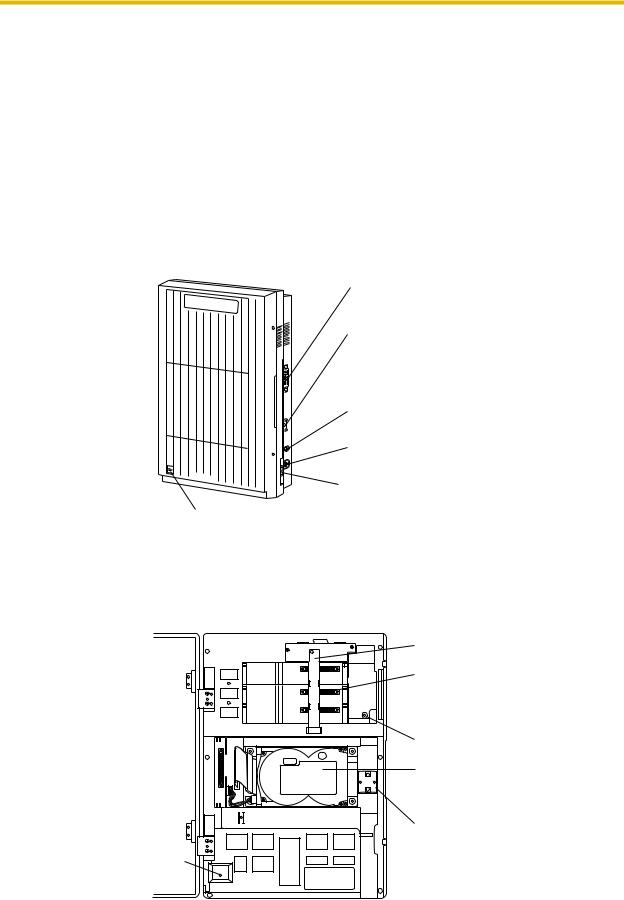
1.3.2 System Components
Main Cabinet
Panasonic
Power Indicator
Note
EIA port is at SELV.
RS-232C
Connector
Earth Terminal
Fuse and fuse rating
AC Inlet
Power Switch
Inside View of the Main Cabinet
SLOT 3
SLOT 2
SLOT 1
Earthing Strap
Slots For
Optional Port
Cards
Rotary Switch
3.5 "Hard Disk
Drive
Ferrite Core
Power Indicator
POWER
Installation Manual |
17 |
|
|

1.3 SYSTEM BASICS
Note
Ports 1-12 are at TNV.
System Components
Power Indicator:
Indicates the system status: when flashing, the system is off-line (not ready to receive calls).
RS-232C Connector:
Connects an ASCII or VT terminal to the VPS that is necessary to program the system.
Earth Terminal:
Should be connected to an earth source with less than 1  resistance.
Fuse:
Protects the system from power line surges and should only be replaced with the same type. Please see the fuse socket on the cabinet for the value of the fuse.
AC Inlet:
Connects the power cable to an AC outlet dedicated to the VPS.
Power Switch:
Starts the system and begins the self-test.
SAFETY PRECAUTION: When making any connections or removing the cover, be sure the power switch is switched off.
Earthing Strap:
Protects the printed circuit board from static electricity.
(Earth) SAFETY PRECAUTION: Discharge any body static by touching the metal bar.
Optional Port Cards:
The following types of port cards can be installed in the VPS.
•Four digital port expansion cards (KX-TVP204)
•Two digital/analogue port expansion cards (KX-TVP102)
KX-TVP102 consists of the following 2 cards:
•Telephone line interface card
•Digital processor (DSP) card
The telephone line interface transmits and receives analogue and digital signals to and from the telephone line. The analogue input signal is digitised at a sampling rate of 8 kHz to create a 16-bit digital signal.
The DSP has the following features:
•Voice Compression and Decompression
•Touchtone Detection
•Touchtone Generation
•Call Progress Tone Detection
KX-TVP204 consists of a telephone line interface and a DSP. The telephone interface of the
18 Installation Manual

1.3 SYSTEM BASICS
KX-TVP204 transmits and receives ONLY digital signals with a Panasonic KX-TD Digital PBX. The DSP has the same features as the KX-TVP102.
MODE (Rotary Switch):
(Check the status of this switch only at start-up.) Provides the following additional functions:
Table 1-1
Position |
Additional Function |
|
|
0 |
Normal setting. |
|
|
1 |
Initialises RS-232C parameters. |
|
RS-232 default parameters: 9,600, N, 8, 1 |
|
|
2* |
Auto Configuration is automatically completed and |
|
all ports are set for Automated Attendant service. |
|
|
3* |
Auto Configuration is automatically completed and |
|
all ports are set for Voice Mail service. |
|
|
4 |
Reserved |
|
|
5 |
Initialises the VPS. Clears all voice data (except |
|
User 1 and User 2 prompts) and returns all system |
|
parameters to the default setting. |
|
|
6 |
Test Mode (Hard Disk Drive Read/Write Test) |
|
|
7 |
Adjust VPS parameters to your PBX quickly. |
|
|
8 |
Initialises the VPS. Clears all voice data and |
|
returns all system parameters to the default |
|
setting. |
|
CAUTION: User 1 and User 2 Prompts will be |
|
erased! |
|
|
9 |
Reserved |
|
|
* For Panasonic KX-TD series telephone systems with DPT Integration
To change the position, use an electrical or jewellers screwdriver etc.
When setting the Rotary Switch to any position (except 0):
1.Disconnect the extension wire(s) and wait a few minutes.
2.Turn the power switch off at the VPS.
3.Set the Rotary Switch.
4.Turn the power switch back on at the VPS.
5.Connect the extension wire(s) to the VPS and wait approximately 5 min.
6.Return the Rotary Switch to position 0.
Hard Disk Drive:
(One/system) Stores the proprietary system programme, the system administration table, the voice prompts (about 50 min worth) and has the recording area for the messages from callers. (The hard disk is controlled by the central micro processor.)
Installation Manual |
19 |
|
|

1.3 SYSTEM BASICS
Note: The actual Hard Disk Drive mounted on your VPS may look different from the one shown in the corresponding illustration provided in the beginning of this section.
CPU Board:
(One/system) Main processing unit for the system. Comprised of central microprocessor, ROM, dynamic RAM, system controller, Rotary Switch, and an RS-232C interface.
1.3.3 Which Phone Systems are Compatible?
We recommend integration with the following Panasonic phone systems:
•Panasonic KX-TD500
•Panasonic KX-TD1232
•Panasonic KX-TD816
•Panasonic KX-TA series
•Panasonic KX-TD612
Note
The KX-TD500 is not sold in the United Kingdom. It is only available in some countries.
We cannot guarantee adequate integration of the VPS with other PBX systems or with Key Systems. If the customer does not have a recommended Panasonic PBX system, be sure that the system has the features listed below.
The PBX should have the following features for successful integration:
•Single line (tip/ring) port circuits (Some PBXs need an OPX card to provide this connection.)
•Extension to extension touchtone signalling
•Message Waiting Notification from an SLT (single-line telephone)
•Screened transfer from an SLT
•Message Waiting Notification on proprietary (multi-line) sets (message waiting lamp accessed by dialling on/off codes)
If the PBX does not have these features, VPS operation will be limited.
See 3.1.4 PBX Requirements for Integration. You will find the following information about each feature listed:
•Description
•Limitations of the system without the feature
•Tests to determine whether the PBX has the feature
VOICE MAIL
The recommended Panasonic PBX systems have Follow-on ID and Inband Integration. When callers are transferred to an extension that is forwarded to Voice Mail, Follow-on ID sends callers directly to the mailbox. Without Follow-on ID, the caller would have to re-enter the mailbox number when connected to Voice Mail.
Touchtone Integration enables the VPS to recognise the current state of the call and improve its call handling performance. When enabled, the PBX informs the VPS of the status of the call (busy, answered, ringing, etc.) by sending a code with touchtones before sending the normal
20 Installation Manual
1.3 SYSTEM BASICS
call progress tones. For example, when a caller hangs up before making a selection, the PBX sends # 9 to the VPS port that answered. This informs the VPS that the caller has hung up. Upon receiving these digits, the VPS goes on-hook and is ready to handle another call.
DPT Integration is available when the VPS is connected to a Panasonic KX-TD series PBX (depending on the software version). This DPT Integration provides the VPS with more information than Touchtone Integration. This information enables the system to identify the extension number of the caller, know where from and why the call is forwarded, and recognise what the caller wants to do. Some features are available only with DPT Integration (Remote Call Forwarding Set, Live Call Screening, Two-Way Recording, Two-Way Transfer, Direct Mailbox Access, Intercom Paging, Auto Configuration, Caller Name Announcement (system/ personal), Caller ID Call Routing, Personal Greeting for Caller ID, Time Synchronisation with PBX).
1.3.4 Installer Equipment and Software Requirements
The installer must have a personal computer or data terminal equipped with terminal emulation software. We suggest that you use something like HyperTerminal by HILGRAEVE. Use the personal computer to program the VPS. Terminal emulation software enables the keyboard to be used as a data entry device.
While both the personal computer and data terminal are working, the personal computer allows screens to be saved in a file throughout the process. It is often helpful to retrieve these files later if technical support is needed.
1.3.5 Specifications
Table 1-2
Compression Rate: |
32 kbps |
Ports (maximum): |
12 ports |
Voice Storage (approximate): |
32 h |
Custom Services: |
100 |
Message Retention: |
1 to 30 days or unlimited |
Number of Mailboxes: |
1022 Subscriber and 2 Manager Mailboxes |
Number of Messages per Mailbox: |
100 maximum (programmable) |
|
|
1.3.6Hardware
•One Hard Disk Drive
•Three Optional Port Card Slots for KX-TVP102 and/or KX-TVP204 Cards
•One RS-232C Connector
•One Rotary Switch
Installation Manual |
21 |
|
|

1.3 SYSTEM BASICS
1.3.7 Expansion Capabilities
Expansion requires additional port card(s): KX-TVP102 or KX-TVP204.
•The KX-TVP102 card has 2 digital/analogue ports, and the ports are increased in increments of 2.
•The KX-TVP204 card has 4 digital ports, and the ports are increased in increments of 4.
1.3.8Recommendations for System Configuration
General guideline: a ratio of 6/1 (for every 6 lines, 1 port). There are 2 questions to ask when considering how many ports are desirable:
•Are the ports answering all incoming calls or just forwarded/transferred calls?
•If they are answering incoming calls, how busy are the lines?
The guideline above (6/1) usually works well with moderate traffic. However, this may have to be modified for heavy traffic. Recommendations are outlined in the following charts.
PBX |
VPS |
Outside (CO) Lines |
Port |
1-6 |
1 |
7-12 |
2 |
13-18 |
3 |
19-24 |
4 |
25-30 |
5 |
31-36 |
6 |
37-42 |
7 |
43-48 |
8 |
49-54 |
9 |
55-60 |
10 |
61-66 |
11 |
67-72 |
12 |
One port may not support an Automated Attendant configuration with 5 outside (CO) lines. The preceding recommendations for Automated Attendant ports may have to be modified for heavy traffic.
22 Installation Manual

1.3 SYSTEM BASICS
PBX |
VPS |
Outside (CO) Lines |
Port |
1-4 |
1 |
5-8 |
2 |
9-12 |
3 |
13-16 |
4 |
17-20 |
5 |
21-24 |
6 |
25-28 |
7 |
29-32 |
8 |
33-36 |
9 |
37-40 |
10 |
41-44 |
11 |
45-48 |
12 |
Installation Manual |
23 |
|
|

1.4 VOICE MAIL INTEGRATION
1.4VOICE MAIL INTEGRATION
1.4.1 General
DPT Integration
To the Panasonic KX-TD digital PBX, the VPS ports look like digital extensions. The PBX thinks that the VPS is a digital phone, and the VPS mimics all actions of a digital set. Another advantage of DPT Integration is that the 2B+D communication provides 2 VPS ports for each Digital Extension port. Communication between the VPS and the PBX through DPT Integration requires the proper software level in the PBX and 4-wire connections for each port. To communicate between the VPS and the PBX through DPT Integration, the PBX and VPS must be programmed to work together.
DPT Integration is available when the VPS is connected to a KX-TD digital PBX with the proper software level.
Note
To use DPT Integration, the lowest numbered jack of the VPS must be connected to the lowest numbered jack assigned as a Voice Mail Port in the KX-TD. See the DPT connection example(s) in the following section, 1.4.2 Connection Examples.
Connect the other jacks to the VPS in the order of Voice Mail Port Assignment in the PBX.
Inband/None Integration
To the PBX, the VPS looks like SLT sets through standard single-line (tip/ring) telephone interfaces.
1.4.2 Connection Examples
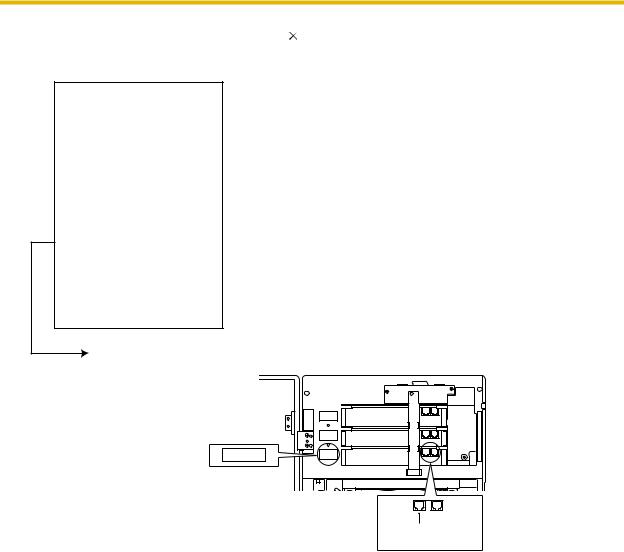
DPT Integration
For example, when you mount 3 KX-TVP204 cards, you can use 12 VPS ports in total by connecting 6 jacks of the KX-TD series PBX to 6 jacks of the VPS.
24 Installation Manual
1.4 VOICE MAIL INTEGRATION
Connection Example (KX-TVP204 |
3) |
|
|
|
|
|
||||||
|
PBX (KX-TD1232) |
|
VPS |
|
|
|
||||||
|
Jack 6 |
|
|
|
|
|
|
|
|
|
|
|
|
|
|
|
|
|
|
|
|
|
|
|
|
|
|
|
|
|
SLOT 3 |
Jack 5 |
Jack 6 |
|
||||
|
|
|
|
|
|
|
||||||
|
Jack 5 |
|
|
|
|
Port 9 Port 10 |
Port 11 Port 12 |
|
||||
|
|
|
|
|
|
|
|
|||||
|
Jack 4 |
|
|
|
|
|
|
|
|
|
|
|
|
|
|
|
|
|
|
|
|
|
|
|
|
|
|
|
|
|
|
|
|
|
|
|
|
|
|
|
|
|
|
SLOT 2 |
Jack 3 |
Jack 4 |
|
||||
|
|
|
|
|
|
|
||||||
|
Jack 3 |
|
|
|
|
Port 5 Port 6 |
Port 7 Port 8 |
|
||||
|
|
|
|
|
|
|
|
|||||
|
|
|
|
|
|
|
|
|
|
|
||
|
Jack 2 |
|
|
|
|
|
|
|
|
|
|
|
|
|
|
|
|
|
|
|
|
|
|
|
|
|
|
|
|
|
SLOT 1 |
Jack 1 |
Jack 2 |
|
||||
|
|
|
|
|
|
|
||||||
|
Jack 1 |
|
|
|
|
Port 1 Port 2 |
Port 3 Port 4 |
|
||||
|
|
|
|
|
|
|
|
|||||
|
|
|
|
|
|
|
|
|
|
|
|
|
|
|
|
|
|
|
|
|
|
|
|
|
|
Assigned as DPT VPS ports
SLOT1
SLOT 3
SLOT 2
SLOT 1
Telephone Line
Modular Jacks
The lowest numbered
jack on the slot.
Installation Manual |
25 |
|
|
1.4 VOICE MAIL INTEGRATION
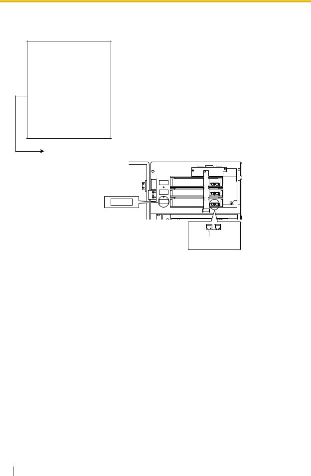
Connection Example (KX-TVP102 3, DPT Integration Mode)
PBX (KX-TD1232) |
|
|
VPS |
|
|
||||
|
|
|
|
|
|
|
|
|
|
Jack 3 |
|
|
|
|
SLOT 3 |
Jack 5 |
Jack 6 |
|
|
|
|
|
|
Port 9 Port 10 |
|
|
|||
|
|
|
|
|
|
|
|
||
|
|
|
|
|
|
|
|
|
|
|
|
|
|
|
|
|
|
|
|
Jack 2 |
|
|
|
|
SLOT 2 |
Jack 3 |
Jack 4 |
|
|
|
|
|
|
Port 5 Port 6 |
|
|
|||
|
|
|
|
|
|
|
|
||
|
|
|
|
|
|
|
|
|
|
|
|
|
|
|
|
|
|
|
|
|
|
|
|
|
|
|
|
|
|
Jack 1 |
|
|
|
|
SLOT 1 |
Jack 1 |
Jack 2 |
|
|
|
|
|
|
Port 1 Port 2 |
|
|
|||
|
|
|
|
|
|
|
|
||
|
|
|
|
|
|
|
|
|
|
|
|
|
|
|
|
|
|
|
|
Assigned as DPT VPS ports
SLOT1
SLOT 3
SLOT 2
SLOT 1
Telephone Line
Modular Jacks
The lowest numbered
jack on the slot.
Connect the odd-numbered jack on each KX-TVP102 card to your PBX (see the diagram above). The VPS will support 2 ports for each KX-TVP102 card, with only one jack connected.
Note
Do not connect the even-numbered jacks on the KX-TVP102 card.
26 Installation Manual
1.4 VOICE MAIL INTEGRATION
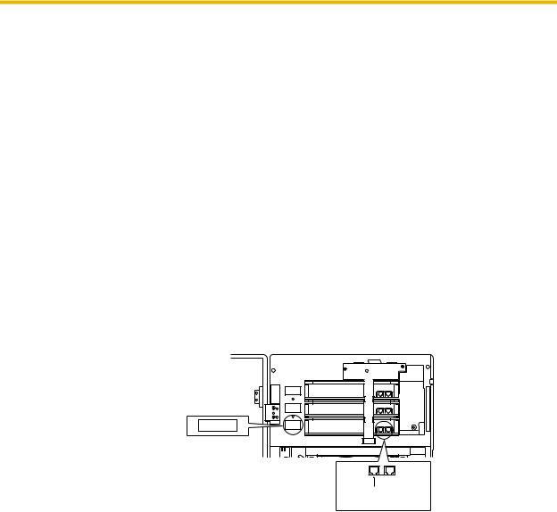
Inband/None Integration
Connection Example (KX-TVP102 3, Inband/None Integration Mode)
PBX (KX-TD1232) |
|
|
|
VPS |
|
|
|
|
|
|
|
||||
Jack 6 |
|
|
|
|
|
|
|
|
|
|
|
|
|
|
|
|
|
|
|
|
|
|
|
|
|
|
|
|
|
|
|
|
|
|
|
SLOT 3 |
|
Jack 5 |
|
Jack 6 |
|
||||||
|
|
|
|
|
|
|
|
||||||||
Jack 5 |
|
|
|
|
|
Port 9 |
Port 10 |
|
|||||||
|
|
|
|
|
|
|
|||||||||
Jack 4 |
|
|
|
|
|
|
|
|
|
|
|
|
|
|
|
|
|
|
|
|
|
|
|
|
|
|
|
|
|
|
|
|
|
|
|
|
|
|
|
|
|
|
|
|
|
|
|
|
|
|
|
SLOT 2 |
|
Jack 3 |
|
Jack 4 |
|
||||||
|
|
|
|
|
|
|
|
||||||||
Jack 3 |
|
|
|
|
|
Port 5 |
|
Port 6 |
|
||||||
|
|
|
|
|
|
|
|
||||||||
|
|
|
|
|
|
|
|
|
|
|
|
|
|
||
Jack 2 |
|
|
|
|
|
|
|
|
|
|
|
|
|
|
|
|
|
|
|
|
|
|
|
|
|
|
|
|
|
|
|
|
|
|
|
SLOT 1 |
|
Jack 1 |
|
Jack 2 |
|
||||||
|
|
|
|
|
|
|
|
||||||||
Jack 1 |
|
|
|
|
|
Port 1 |
|
Port 2 |
|
||||||
|
|
|
|
|
|
|
|
||||||||
|
|
|
|
|
|
|
|
|
|
|
|
|
|
|
|
|
|
|
|
|
|
|
|
|
|
|
|
|
|
|
|
|
|
|
|
|
|
|
|
|
|
|
|
|
|
|
|
|
|
|
|
|
|
|
|
|
|
|
|
|
|
|
|
|
|
|
|
|
|
|
|
|
|
|
|
|
|
|
|
|
|
|
|
|
|
|
|
|
|
|
|
|
|
|
|
SLOT1
SLOT 3
SLOT 2
SLOT 1
Telephone Line
Modular Jacks
The lowest numbered
jack on the slot.
Connect both jacks on each KX-TVP102 card to your PBX (see the diagram above). The VPS will support 2 ports for each KX-TVP102 card, with both jacks connected.
Installation Manual |
27 |
|
|

1.4 VOICE MAIL INTEGRATION
28 Installation Manual

Section 2
INSTALLATION
Installation Manual |
29 |
|
|

2.1 SAFETY PRECAUTIONS
2.1SAFETY PRECAUTIONS
Please read the following precautions before installing the VPS.
2.1.1 Installation
The VPS needs to be mounted on a wall. Improper placement of the system may result in malfunction, noise, or discolouration. Avoid installing the VPS in the following places:
•in direct sunlight; in hot, cold, or humid places
•in areas where there are thermal springs, etc. (where sulphuric gas may damage the equipment or contacts).
•where shocks or vibrations are frequent or strong.
•in dusty places or places where water or oil may come in contact with the unit.
•near high frequency generating devices such as sewing machines, elevators or electric welders.
•on or near computers, telexes, or other office equipment; near microwave ovens or air conditioners. (Ideally, the VPS should not be in the room with these items and should be at least 1.8 m away from televisions.)
Do not obstruct the areas around the PBX and the VPS. Both require space above for cooling and space on the sides for maintenance and inspection.
30 Installation Manual
Loading...