


LH-512
INSTRUCTION MANUAL
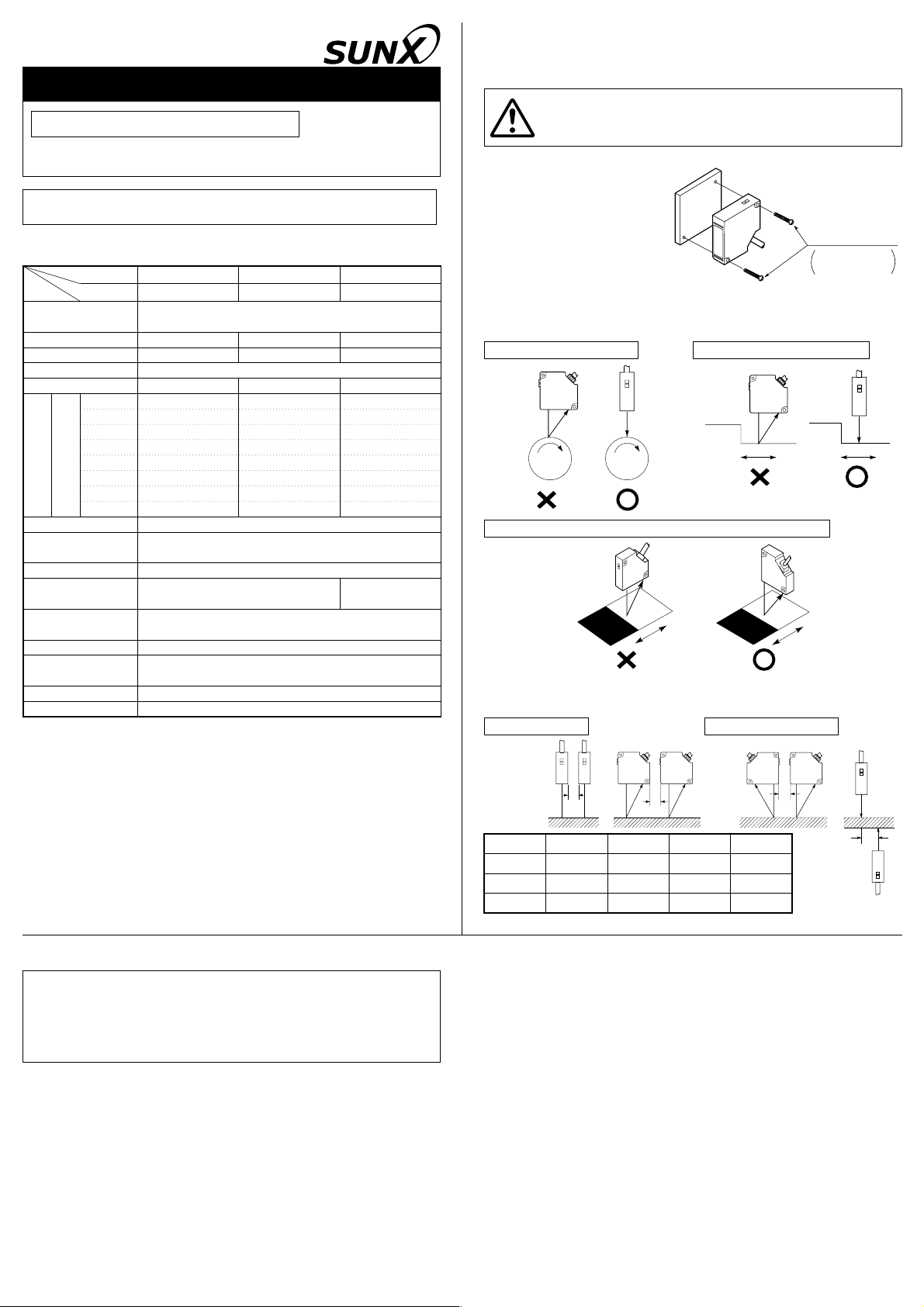
M3 screws
Please arrange
separately.
A
B
C
D
LED Type Optical Displacement Sensor
Sensor Head
Thank you very much for using SUNX sensors. Please read this
Instruction Manual carefully and thoroughly for the correct and optimum
use of this sensor. Kindly keep this manual in a convenient place for
quick reference.
This product is not a safety sensor. Its use is not intended or designed
to protect life and prevent body injury or property damage from
dangerous parts of machinery. It is a normal object detection sensor.
LH-50
Series
For details, please refer to the User’s Manual of the controller
LH-CL6(P) or LH-CS6(P)/LH-CD6(P).
z SPECIFICATIONS
Type
Item
Applicable
Controller (Note 2)
Center measuring distance
Measuring range
Emitting element Red LED (modulated, peak wavelength: 650nm)
Spot diameter (Note 3)
Linearity (Note 5) Within Ѱ0.2% F.S.
Ambient temperature
Ambient humidity 35 to 85% RH, Storage: 35 to 85% RH
Ambient illuminance
(Incandescent light)
Protection
(Except connector part)
Material Enclosure: PEI, Enclosure cover: Aluminum
Cable
Cable extension Extension up to total 10.2m is possible with optional cable.
Weight 70g approx. (with cable), 45g approx. (without cable)
Notes:
1) Conditions which have not been specified are to be taken as: use of an applicable
controller, 24V DC supply voltage, Ҥ 20ѵ ambient temperature, SELECT gain
setting, 300ms response time setting, center measuring distance, interference
prevention function not used and white ceramic board object.
2) For details of the applicable controller, please refer to the instruction manual of the
controller.
3) This is the value at the center measuring distance, and is based on the definition of
1/e
spreads out of the specified spot diameter and, depending on the conditions
around the measured object, may affect the measurement accuracy.
4) This is the typical value at the center measuring distance for a white ceramic board
object. The given values are for the analog output of the applicable controller.
5) This is the value for white ceramic board object. The linearity may differ depending on
the measured object. The given value is for the analog output of the applicable
controller.
Model No.
300ms 2 m4m20m
100ms 4 m8m40m
40ms 5 m14m65m
30ms 6 m16m75m
20ms 7 m28m92m
10ms 10 m40m 130m
Resolution (Note 4)
2
(13.5%) of the beam axis light intensity. Take care that some amount of light
1ms 20 m 120 m 400 m
Controller response time
0.5ms 40 m 160 m 580 m
40mm type
LH-54 LH-58 LH-512
LH-CL6(P), LH-CS6(P), LH-CD6(P)
40mm 80mm 120mm
Ѱ10mm (30 to 50mm) Ѱ20mm (60 to 100mm) Ѱ30mm (90 to 150mm)
1.6mm or less 2.0mm or less 3.0mm or less
0 to Ҥ45ѵ (No dew condensation allowed)
Storage: ҥ20 to Ҥ 60ѵ
3,000Rx or less 2,000Rx or less
0. 22mm
0.2m long, with a connector at the end
80mm type 120mm type
IP67 (IEC)
2
11-core composite cabtyre cable,
x MOUNTING
ӟ Install the sensor head
such that the sensing
surface of the sensor head
and the measured object
are parallel. The screw
tightening torque should be
0.5NОm or less.
ӟ In case the measured object is moving as shown below, take care of
the mounting direction of the sensor head, as an error may be
generated depending on the mounting direction.
Eccentricity measurement
In case of extreme change in color or material at a boundary
ӟ In case several sensor heads are arranged in a row, mount them by
keeping the minimum distance given below.
Parallel mounting Face-to-face mounting
Model No. A C D
LH-54
LH-58
LH-512
Note: The above values are for the case when the interference prevention function is used.
0mm 10mm 17mm
0mm 10mm 17mm
0mm 30mm 17mm
B
0mm
0mm
0mm
Level difference measurement
c CAUTIONS
The sensor head has been designed to meet the specifications
when used along with the optional exclusive controller. In case it is
used in a combination that does not use the optional exclusive
controller, not only the specifications may not be met, but it may also
cause an accident, etc. Hence, always use the sensor head along
with the exclusive controller.
ӟ Take care that wrong wiring will damage the sensor.
ӟ Use this product 10min. after the power is supplied. Immediately on
supply of power, the electrical circuit is yet to stabilize, which may
cause variation in measured values.
ӟ Do not allow any water, oil, fingerprints, etc., which may refract light,
or dust, dirt, etc., which may block light, to stick to the
emitting/receiving surfaces of the sensor head. In case they are
present, wipe them with a clean, soft cloth or lens paper.
ӟ Take care that in case the measured object has a highly reflective
surface or is transparent, accurate measurement may not be
possible.
ӟ Although this sensor uses a red LED as the beam source, do not
directly see the beam emitted from the sensor head, since it has
been focused and has high optical intensity.
ӟ Take care that extraneous light, such as sunlight or light having the
same wavelength, does not fall on the receiving part of the sensor
head. Especially for accurate measurements, install a shield, etc., to
block extraneous light.
Although the sensor head has IP67 protection, measurement in water
ӟ
or rain is not possible. Further, the connector part is not water-proof.
ӟ Avoid use at places subject to intense vibrations or shock.
ӟ Avoid dust, dirt, and steam.
ӟ Take care that the sensor head does not come in direct contact with
water, oil, grease, or organic solvents, such as, thinner, etc.
ӟ In case noise generating equipment (switching regulator, inverter
motor, etc.) is used in the vicinity of this product, connect the frame
ground (F.G.) terminal of the equipment to an actual ground.
ӟ Do not run the wires together with high-voltage lines or power lines
or put them in the same raceway. This can cause malfunction due to
induction.
ӟ This sensor is suitable for indoor use only.
 Loading...