


Model No. NTEVEX18718.0
Serial No.
Write the serial number in the space above for reference.
Serial Number
Decal
CUSTOMER SERVICE
UNITED KINGDOM
Call: 0330 123 1045
From Ireland: 053 92 36102
Website: iconsupport.eu
E-mail: csuk@iconeurope.com
Write:
ICON Health & Fitness, Ltd. Unit 4, Westgate Court Silkwood Park
OSSETT
WF5 9TT
UNITED KINGDOM
AUSTRALIA Call: 1800 993 770
E-mail: australiacc@iconfitness.com
Write:
ICON Health & Fitness PO Box 635
WINSTON HILLS NSW 2153 AUSTRALIA
 CAUTION
Read all precautions and instructions in this manual before using this equipment. Keep this manual for future reference.
USER’S MANUAL
iconeurope.com
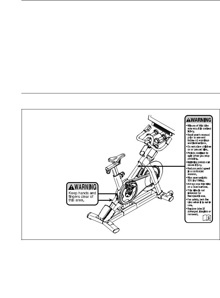
TABLE OF CONTENTS |
|
WARNING DECAL PLACEMENT . . . . . . . . . . . . . . . . . . . . . . . . . . . . . . . . . . . . . . . . . . . . . . . . . . . . . |
. . . . . . . . . .2 |
IMPORTANT PRECAUTIONS. . . . . . . . . . . . . . . . . . . . . . . . . . . . . . . . . |
3 |
BEFORE YOU BEGIN. . . . . . . . . . . . . . . . . . . . . . . . . . . . . . . . . . . . . . . . . . . . . . . . . . . . . . . . . . . . . . |
. . . . . . . . . .5 |
PART IDENTIFICATION CHART. . . . . . . . . . . . . . . . . . . . . . . . . . . . . . . . . . . . . . . . . . . . . . . . . . . . . . . |
. . . . . . . . .6 |
ASSEMBLY . . . . . . . . . . . . . . . . . . . . . . . . . . . . . . . . . . . . . . . . . . . . . . . . . . . . . . . . . . . . . . . . . . . . . . . |
. . . . . . . . .7 |
HOW TO USE THE STUDIO CYCLE. . . . . . . . . . . . . . . . . . . . . . . . . . |
. . . . 15 |
MAINTENANCE AND TROUBLESHOOTING . . . . . . . . . . . . . . . . . . . . . . . . . . |
30 |
EXERCISE GUIDELINES. . . . . . . . . . . . . . . . . . . . . . . . . . . . . . |
. . . . .33 |
PART LIST. . . . . . . . . . . . . . . . . . . . . . . . . . . . . . . . . . . . . . . . . . . . . . . . . . . . . . . . . . . . . . . . . . . . . . . . |
. . . . . . . .36 |
EXPLODED DRAWING. . . . . . . . . . . . . . . . . . . . . . . . . . . . . . . . . . . . . . . . . . . . . . . . . . . . . . . . . . . . . . |
. . . . . . . .38 |
ORDERING REPLACEMENT PARTS. . . . . . . . . . . . . . . . . . . . . . . . . . . . . . . . . . . . . . . . . . . . . . . . . . . |
Back Cover |
RECYCLING INFORMATION. . . . . . . . . . . . . . . . . . . . . . . . . . . . . |
Back Cover |
WARNING DECAL PLACEMENT
This drawing shows the location(s) of the warning decal(s). If a decal is missing or illegible, see the front cover of this manual and request a free replacement decal. Apply the decal in the location shown. Note: The decal(s) may not be
shown at actual size.
NORDICTRACK and IFIT are registered trademarks of ICON Health & Fitness, Inc. The Bluetooth® word mark and logos are registered trademarks of Bluetooth SIG, Inc. and are used under license. Google Maps is a trademark of Google LLC. Wi-Fi is a registered trademark of Wi-Fi Alliance. WPA and WPA2 are trademarks of Wi-Fi Alliance.
2

IMPORTANT PRECAUTIONS
 WARNING:To reduce the risk of burns, fire, electric shock, or injury to persons, read all important precautions and instructions in this manual and all warnings on your studio cycle before using your studio cycle. ICON assumes no responsibility for personal injury or property damage sustained by or through the use of this product.
1.It is the responsibility of the owner to ensure that all users of the studio cycle are adequately informed of all precautions.
2.Before beginning any exercise program, consult your physician. This is especially important for persons over age 35 or persons with pre-existing health problems.
3.The studio cycle is not intended for use by persons with reduced physical, sensory, or mental capabilities or lack of experience and knowledge, unless they are given supervision or instruction about use of the studio cycle by someone responsible for their safety.
4.Use the studio cycle only as described in this manual.
5.The studio cycle is intended for home use only. Do not use the studio cycle in a commercial, rental, or institutional setting.
6.Keep the studio cycle indoors, away from moisture and dust. Do not put the studio cycle in a garage or covered patio, or near water.
7.Place the studio cycle on a level surface with at least 2 ft. (0.6 m) of clearance around the studio cycle. To protect the floor or carpet from damage, place a mat under the studio cycle.
8.Inspect and properly tighten all parts each time the studio cycle is used. Replace any worn parts immediately.
9.Keep children under age 13 and pets away from the studio cycle at all times.
10.When connecting the power cord (see page 15), plug the power cord into a grounded circuit.
11.Do not modify the power cord or use an adapter to connect the power cord to an improper receptacle. Keep the power cord away from heated surfaces. Do not use an extension cord.
12.Do not operate the studio cycle if the power cord or plug is damaged, or if the studio cycle is not working properly.
13.DANGER:Always unplug the power cord and press the power switch to the off position when the studio cycle is not in use and before cleaning the studio cycle. Servicing other than the procedures in this manual should be performed by an authorized service representative only.
14.Wear appropriate clothes while exercising; do not wear loose clothes that could become caught on the studio cycle. Always wear athletic shoes for foot protection.
3

15.The studio cycle should not be used by persons weighing more than 330 lbs. (150 kg).
16.Be careful when mounting and dismounting the studio cycle.
17.Always keep your back straight while using the studio cycle; do not arch your back.
18.The studio cycle does not have a freewheel; the pedals will continue to move until the flywheel stops. Reduce your pedaling speed in a controlled way.
19.To stop the flywheel quickly, press the brake knob downward.
20.When the studio cycle is not in use, press the brake knob downward and tighten it firmly.
21.Over exercising may result in serious injury or death. If you feel faint, if you become short of breath, or if you experience pain while exercising, stop immediately and cool down.
SAVE THESE INSTRUCTIONS
4
BEFORE YOU BEGIN
Congratulations for selecting the revolutionary NORDICTRACK® COMMERCIAL S22I STUDIO CYCLE. The COMMERCIAL S22I STUDIO CYCLE is unlike any ordinary exercise bike. With full adjustability, an interactive wireless touchscreen console, an incline system that simulates real-world terrain, and an array of other features, the COMMERCIAL S22I STUDIO CYCLE provides an immersive in-home studio cycling experience.
For your benefit, read this manual carefully before you use the studio cycle. If you have questions after
reading this manual, please see the front cover of this manual. To help us assist you, note the product model number and serial number before contacting us. The model number and the location of the serial number decal are shown on the front cover of this manual.
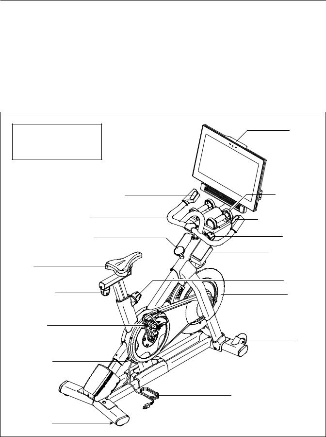
Before reading further, please familiarize yourself with the parts that are labeled in the drawing below.
Length: 2 ft. 11 in. (89 cm) |
Console |
Width: 1 ft. 10 in. (56 cm) |
|
Weight: 176 lbs. (80 kg) |
|
Incline/Decline Control |
Hand Weight |
Handlebar |
Resistance Control |
|
|
Brake Knob |
Post Knob |
|
Accessory Tray |
Saddle |
|
|
Post Knob |
Carriage Knob |
Flywheel |
Pedal/Strap |
|
|
Wheel |
Power Switch |
|
|
Power Cord |
Leveling Foot |
|
|
5 |
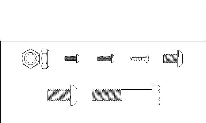
PART IDENTIFICATION CHART
Use the drawings below to identify the small parts needed for assembly. The number in parentheses below each
drawing is the key number of the part, from the PART LIST near the end of this manual. The number following the key number is the quantity needed for assembly. Note: If a part is not in the hardware kit, check to see if it has been preassembled. Extra parts may be included.
|
|
|
|
|
|
|
|
|
|
|
|
|
|
|
M10 Jam Nut |
M4 x 10mm |
M4 x 12mm |
M4 x 14mm |
|
|
|
||||||||
|
M8 x 12mm |
|||||||||||||
Machine Screw |
Machine Screw |
Screw (17)–4 |
|
|||||||||||
(95)–1 |
(12)–2 |
(102)–4 |
|
|
|
|
|
Screw (93)–4 |
||||||
|
|
|
|
|
|
|
|
|
|
|
|
|
|
|
|
|
|
|
|
|
|
|
|
|
|
|
|
|
|
|
|
|
|
|
|
|
|
|
|
|
|
|
|
|
|
|
|
|
|
|
|
|
|
|
|
|
|
|
|
|
|
|
|
|
|
|
|
|
|
|
|
|
|
|
|
|
|
|
|
|
|
|
|
|
|
|
|
|
|
M10 x 20mm Screw |
M10 x 52mm Bolt (94)–1 |
(105)–12 |
|
6
ASSEMBLY
•Assembly requires two persons.
•Place all parts in a cleared area and remove the packing materials. Do not dispose of the packing materials until you complete all assembly steps.
•To identify small parts, see page 6.
•To avoid damaging parts, do not use power tools.
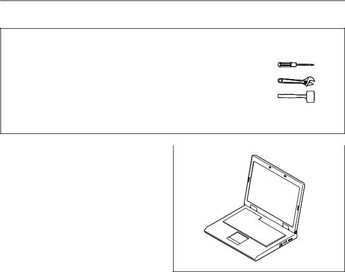
•In addition to the included tool(s), assembly requires the following tool(s):
one Phillips screwdriver
one adjustable wrench
one rubber mallet
Assembly may be easier if you have a set of wrenches.
1. To register your product and activate your |
|
|
|
|
|
|
|
|
1 |
|
|
warranty in the UK, go to iconsupport.eu. If |
|
|
|
|
|
||
you do not have internet access, call Customer |
|
|
|
Service (see the front cover of this manual). |
|
|
|
To register your product and activate your warranty in Australia, email or post the
following information to the email address or postal address on the front cover of this manual.
•your receipt (make sure to keep a copy)
•your name, address, and telephone number
•the model number, serial number, and name of your product (see the front cover of this manual)
7
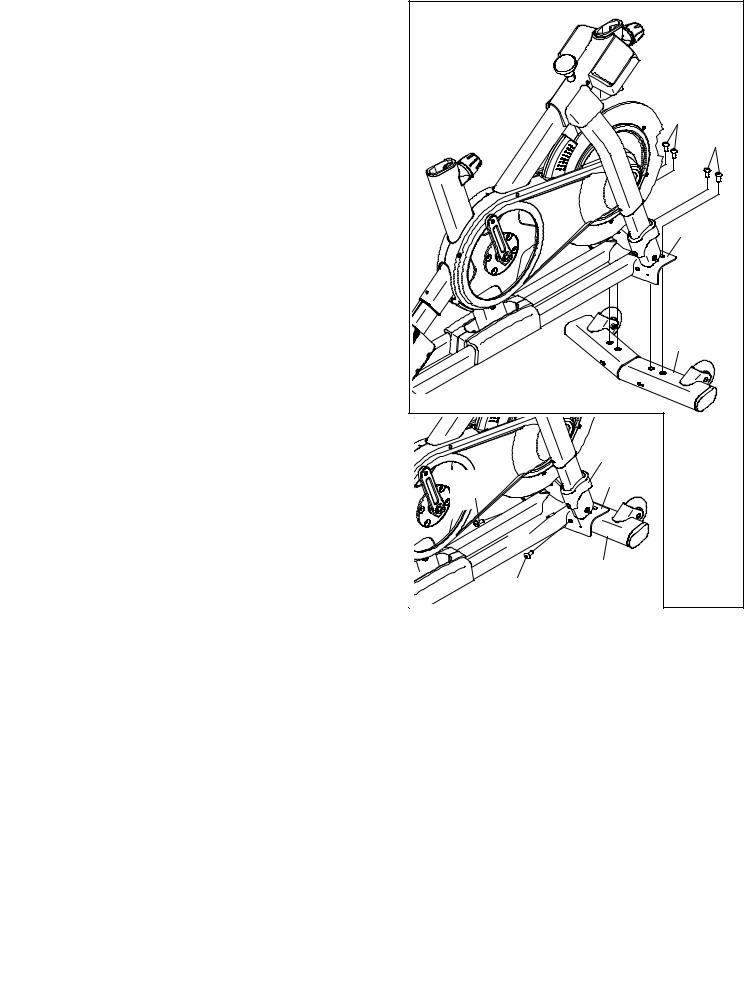
2. Attach the Front Stabilizer (3) to the Base (2) |
2 |
|
with four M10 x 20mm Screws (105); do not |
|
|
|
|
|
fully tighten the Screws yet. |
|
|
See the inset drawing. Finish attaching |
|
|
the Front Stabilizer (3) with two additional |
|
|
M10 x 20mm Screws (105). |
|
105 |
Then, fully tighten all six M10 x 20mm |
|
|
|
105 |
|
Screws (105). |
|
|
|
|
|
See the inset drawing. Press the right Leg |
|
|
Cover (64) downward and attach it to the Base |
|
|
(2) with an M4 x 10mm Machine Screw (12). |
|
2 |
Attach the other Leg Cover (not shown) in the |
|
|
same way. |
|
|
|
|
3 |
|
|
64 |
|
105 |
2 |
|
|
|
|
|
12 |
|
|
3 |
|
|
105 |
8
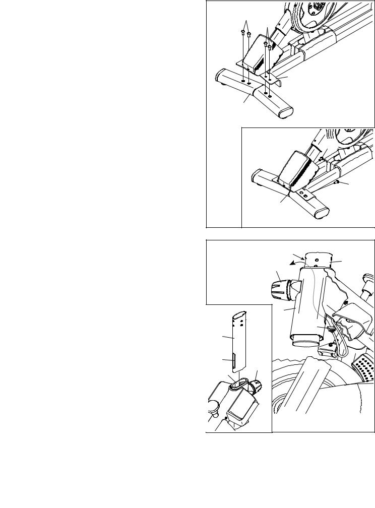
3. Attach the Rear Stabilizer (4) to the Base (2) |
3 |
|
|
|
with four M10 x 20mm Screws (105); do not |
|
105 |
|
|
|
|
|
||
fully tighten the Screws yet. |
|
|
|
|
|
|
|
105 |
|
See the inset drawing. Finish attaching |
|
|
|
|
the Rear Stabilizer (4) with two additional |
|
|
|
|
M10 x 20mm Screws (105). |
|
|
|
|
Then, fully tighten all six M10 x 20mm |
|
|
|
|
Screws (105). |
|
|
|
2 |
|
|
|
4 |
|
|
|
|
|
105 |
|
|
|
|
105 |
|
|
|
4 |
|
4. See the inset drawing. Orient the Handlebar |
4 |
|
|
|
Post (7) so that the lower slot (A) is on the side |
|
|
B |
|
shown. |
|
|
100 |
7 |
|
|
|
||
Next, loosen the indicated Post Knob (100) and |
|
|
|
|
|
|
|
|
|
insert the Handlebar Post (7) into the Frame |
|
|
|
|
(1) until the lower end of the Handlebar Post is |
|
|
|
|
below the Frame. Then, tighten the Post Knob. |
|
|
|
|
Then, insert the end of the Lower Wire (122) into |
|
|
1 |
|
|
|
|
|
|
the Frame (1) and the Handlebar Post (7) and |
|
|
|
122 |
pull it out of the upper slot (B) in the Handlebar |
|
7 |
|
|
|
|
|
||
Post as shown by the dashed line at the right. |
|
|
|
|
|
|
|
|
|
|
|
A |
100 |
|
|
|
1 |
|
|
|
|
|
|
|
|
9 |
|
|
|
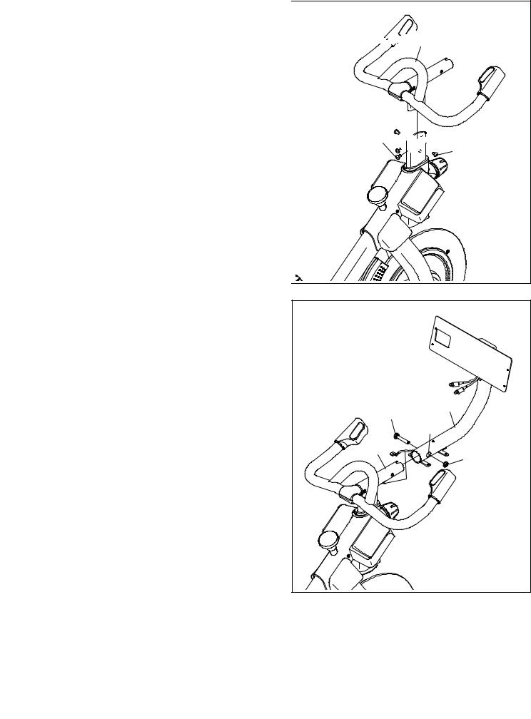
5. Insert the Handlebar (97) into the Handlebar |
|
5 |
|
|
|||
Post (7). Attach the Handlebar with four |
|
||
|
|
|
|
M8 x 12mm Screws (93); start all the Screws, |
|
|
|
and then tighten them. |
|
|
|
|
|
|
|
|
|
|
|
|
|
|
|


 97
97
93


 7 93
7 93
6.Tip: Avoid pinching the wires (C). Slide the Console Support (8) onto the Handlebar (97).
Attach the Console Support (8) with an M10 x 52mm Bolt (94) and an M10 Jam Nut (95); make sure that the Jam Nut is in the
hexagonal hole (D). Do not fully tighten the Bolt yet.
6 |
|
|
Avoid pinching |
|
|
the wires (C) |
8 |
|
94 |
||
|
||
D |
|
|
97 |
95 |
|
|
||
C |
|
|
10 |
|
7.Look under the Console Support (8) and identify the Upper Wire (123), which has a larger connector than the Extension Wire (124).
Connect the Upper Wire (123) to the Lower Wire (122) extending from the Handlebar Post (7). Then, insert the connectors on both Wires into the Handlebar Post.
Next, connect the Extension Wire (124) to the Control Wire (125) extending from the Handlebar (97). Then, insert the connectors on both Wires into the Handlebar.
8.Have a second person hold the Console (10) near the Console Bracket (11).
Plug the Upper Wire (123) and the Extension Wire (124) into the receptacles on the back of the Console (10); make sure to plug the Wire marked with red into the receptacle marked with red, and plug the Wire marked with yellow into the receptacle marked with yellow.
Tip: Avoid pinching the wires. If necessary, tilt the Console Bracket (11) upward to make this step easier. Attach the Console (10) to the Console Bracket with four M4 x 12mm Machine Screws (102); start all the Machine Screws, and then tighten them.
7 |
|
|
|
|
8 |
97 |
|
|
|
|
|
123 |
|
|
125 |
|
|
124 |
|
122 |
|
|
7 |
|
|
|
|
8 |
|
|
11 |
|
|
10 |
|
|
|
102 |
|
|
|
|
|
|
|
|
102 |
|
|
|
123 |
|
|
|
124 |
Avoid pinching the wires
11
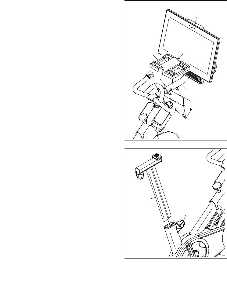
9. |
IMPORTANT: Have a second person move |
9 |
|
|
the Console (10) to a level position. While |
|
|
|
|
|
|
|
the second person holds the Console steady, |
|
10 |
|
tighten the M10 x 52mm Bolt (94). |
|
|
|
Next, orient the Hand Weight Tray (38) so that |
Avoid |
|
|
the largest opening (E) is facing forward. |
pinching |
|
|
|
the wires |
|
|
Tip: Avoid pinching the wires (C). Attach the |
(C) |
|
|
Hand Weight Tray (38) to the Console Support |
|
E |
|
(8) with four M4 x 14mm Screws (17); start all |
38 |
|
|
the Screws, and then tighten them. |
|
|
|
|
|
|
|
|
C 94 |
|
|
|
|
8 |
|
|
|
17 |
10. |
Orient the Saddle Post (13) as shown. |
10 |
|
|
|
|
|
|
Loosen the indicated Post Knob (100). Next, |
|
|
|
insert the Saddle Post (13) into the Frame (1), |
|
|
|
and slide the Saddle Post to the desired height. |
|
|
|
Then, tighten the Post Knob. |
|
|
|
|
13 |
|
|
|
|
100 |
|
|
1 |
|
|
|
12 |
|
 Loading...