


Nordictrack NTL19815.0 User Manual
www.nordictrack.com
Model No. NTL19815.0
Serial No.
Write the serial number in the space
above for reference.
Serial
Number
Decal
ACTIVATE YOUR
WARRANTY
To register your product and
activate your warranty today, go
to www.nordictrackservice.com/
registration.
USER'S MANUAL
CUSTOMER CARE
For service at any time, go to
www.nordictrackservice.com.
Or call 1-800-TO-BE-FIT
(1-800-862-3348)
Mon.–Fri. 6 a.m.–6 p.m. MT
Sat. 8 a.m.–12 p.m. MT
Please do not contact the store.
CAUTION
Read all precautions and instructions in this manual before using
this equipment. Save this manual
for future reference.
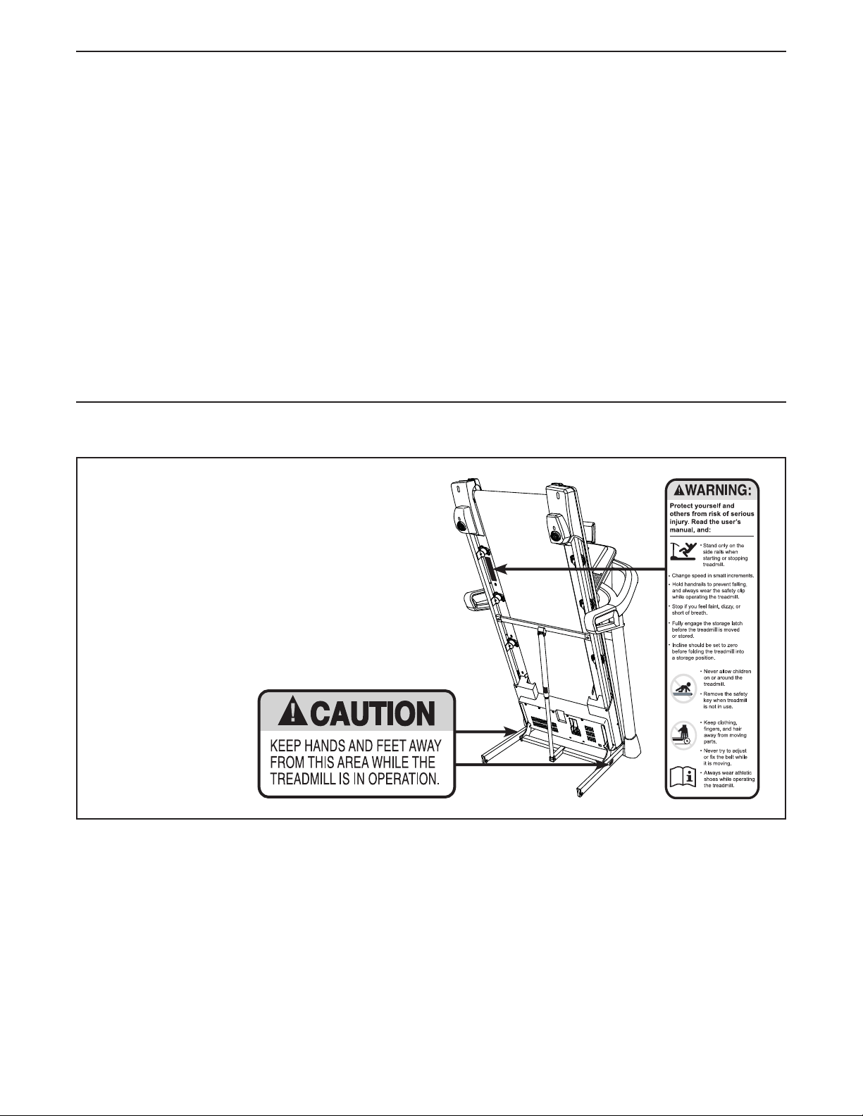
TABLE OF CONTENTS
WARNING DECAL PLACEMENT . . . . . . . . . . . . . . . . . . . . . . . . . . . . . . . . . . . . . . . . . . . . . . . . . . . . . . . . . . . . . . .2
IMPORTANT PRECAUTIONS . . . . . . . . . . . . . . . . . . . . . . . . . . . . . . . . . . . . . . . . . . . . . . . . . . . . . . . . . . . . . . . . . .3
BEFORE YOU BEGIN. . . . . . . . . . . . . . . . . . . . . . . . . . . . . . . . . . . . . . . . . . . . . . . . . . . . . . . . . . . . . . . . . . . . . . . . 7
PART IDENTIFICATION CHART. . . . . . . . . . . . . . . . . . . . . . . . . . . . . . . . . . . . . . . . . . . . . . . . . . . . . . . . . . . . . . . .8
ASSEMBLY . . . . . . . . . . . . . . . . . . . . . . . . . . . . . . . . . . . . . . . . . . . . . . . . . . . . . . . . . . . . . . . . . . . . . . . . . . . . . . . .9
HOW TO USE THE TREADMILL . . . . . . . . . . . . . . . . . . . . . . . . . . . . . . . . . . . . . . . . . . . . . . . . . . . . . . . . . . . . . .20
HOW TO FOLD AND MOVE THE TREADMILL . . . . . . . . . . . . . . . . . . . . . . . . . . . . . . . . . . . . . . . . . . . . . . . . . . . 35
MAINTENANCE AND TROUBLESHOOTING . . . . . . . . . . . . . . . . . . . . . . . . . . . . . . . . . . . . . . . . . . . . . . . . . . . . . 36
EXERCISE GUIDELINES . . . . . . . . . . . . . . . . . . . . . . . . . . . . . . . . . . . . . . . . . . . . . . . . . . . . . . . . . . . . . . . . . . . .39
PART LIST. . . . . . . . . . . . . . . . . . . . . . . . . . . . . . . . . . . . . . . . . . . . . . . . . . . . . . . . . . . . . . . . . . . . . . . . . . . . . . . .42
EXPLODED DRAWING. . . . . . . . . . . . . . . . . . . . . . . . . . . . . . . . . . . . . . . . . . . . . . . . . . . . . . . . . . . . . . . . . . . . . .44
ORDERING REPLACEMENT PARTS. . . . . . . . . . . . . . . . . . . . . . . . . . . . . . . . . . . . . . . . . . . . . . . . . . . Back Cover
LIMITED WARRANTY. . . . . . . . . . . . . . . . . . . . . . . . . . . . . . . . . . . . . . . . . . . . . . . . . . . . . . . . . . . . . . . Back Cover
WARNING DECAL PLACEMENT
This drawing shows the locations of the warning
decals. If a decal is missing or illegible, call the
telephone number on the front cover of this
manual and request a free replacement decal.
Apply the decal in the location shown. Note:
The decals may not be shown at actual size.
IFIT is a registered trademark of ICON Health & Fitness, Inc. App store is a trademark of Apple Inc., registered
in the U.S. and other countries. Android and Google Play are trademarks of Google Inc. The BLUETOOTH® word
mark and logos are registered trademarks of Bluetooth SIG, Inc. and are used under license. IOS is a trademark
or registered trademark of Cisco in the U.S. and other countries and is used under license.
NORDICTRACK is a registered trademark of ICON Health & Fitness, Inc.
2

IMPORTANT PRECAUTIONS
WARNING: To reduce the risk of burns, fire, electric shock, or injury to persons, read
all important precautions and instructions in this manual and all warnings on your treadmill before
using your treadmill. ICON assumes no responsibility for personal injury or property damage sustained by or through the use of this product.
1. It is the responsibility of the owner to ensure
that all users of this treadmill are adequately
informed of all warnings and precautions.
2. Before beginning any exercise program,
consult your physician. This is especially
important for persons over age 35 or persons
with pre-existing health problems.
3. The treadmill is not intended for use by
persons with reduced physical, sensory, or
mental capabilities or lack of experience and
knowledge, unless they have been given
supervision or instruction concerning use
of the treadmill by someone responsible for
their safety.
4. Use the treadmill only as described in this
manual.
5. The treadmill is intended for home use only.
Do not use the treadmill in any commercial,
rental, or institutional setting.
6. Keep the treadmill indoors, away from moisture and dust. Do not put the treadmill in a
garage or covered patio, or near water.
7. Place the treadmill on a level surface, with
at least 8 ft. (2.4 m) of clearance behind it
and 2 ft. (0.6 m) on each side. Do not place
the treadmill on any surface that blocks air
openings. To protect the floor or carpet from
damage, place a mat under the treadmill.
12. Wear appropriate exercise clothes while
using the treadmill. Do not wear loose
clothes that could become caught in the
treadmill. Athletic support clothes are recommended for both men and women. Always
wear athletic shoes. Never use the treadmill
with bare feet, wearing only stockings, or in
sandals.
13. Plug the power cord into a surge suppressor
(not included), and plug the surge suppressor into an appropriate outlet (see page
20). To avoid overloading the circuit, do
not plug other electrical devices, except for
low-power devices such as cell phone chargers, into the surge suppressor or into an
outlet on the same circuit.
14. Use only a surge suppressor that meets
all of the specifications described on page
20. To purchase a surge suppressor, see
your local NORDICTRACK dealer, call the
telephone number on the front cover of this
manual, or see your local electronics store.
15. Failure to use a properly functioning surge
suppressor could result in damage to the
control system of the treadmill. If the control
system is damaged, the walking belt may
slow, accelerate, or stop unexpectedly, which
may result in a fall and serious injury.
16. Keep the power cord and the surge suppressor away from heated surfaces.
8. Do not operate the treadmill where aerosol
products are used or where oxygen is being
administered.
9. Keep children under age 13 and pets away
from the treadmill at all times.
10. The treadmill should be used only by persons weighing 325 lbs. (147 kg) or less.
11. Never allow more than one person on the
treadmill at a time.
17. Never move the walking belt while the power
is turned off. Do not operate the treadmill
if the power cord or plug is damaged, or if
the treadmill is not working properly. (See
MAINTENANCE AND TROUBLESHOOTING
on page 36 if the treadmill is not working
properly.)
18. Read, understand, and test the emergency
stop procedure before using the treadmill
(see HOW TO TURN ON THE POWER on
page 22). Always wear the clip while using the
treadmill.
3

19. Always stand on the foot rails when starting
or stopping the walking belt. Always hold the
handrails while using the treadmill.
26. When folding or moving the treadmill, make
sure that the storage latch is holding the
frame securely in the storage position.
20. When a person is walking on the treadmill,
the noise level of the treadmill will increase.
21. Keep fingers, hair, and clothing away from
the moving walking belt.
22. The treadmill is capable of high speeds.
Adjust the speed in small increments to
avoid sudden jumps in speed.
23. The heart rate monitor is not a medical
device. Various factors, including the user’s
movement, may affect the accuracy of heart
rate readings. The heart rate monitor is
intended only as an exercise aid in determining heart rate trends in general.
24. Never leave the treadmill unattended while it
is running. Always remove the key, press the
power switch into the off position (see the
drawing on page 7 for the location of the
power switch), and unplug the power cord
when the treadmill is not in use.
25. Do not attempt to move the treadmill until it
is properly assembled. (See ASSEMBLY on
page 9 and HOW TO FOLD AND MOVE
THE TREADMILL on page 35.) You must be
able to safely lift 45 lbs. (20 kg) to move the
treadmill.
27. Do not change the incline of the treadmill by
placing objects under the treadmill.
28. Never insert any object into any opening on
the treadmill.
29. Inspect and properly tighten all parts each
time the treadmill is used.
30. DANGER: Always unplug the power
cord immediately after use, before cleaning the treadmill, and before performing the
maintenance and adjustment procedures
described in this manual. Never remove the
motor hood unless instructed to do so by an
authorized service representative. Servicing
other than the procedures in this manual
should be performed by an authorized service representative only.
31. Over exercising may result in serious injury
or death. If you feel faint, if you become short
of breath, or if you experience pain while
exercising, stop immediately and cool down.
32. IMPORTANT: To satisfy exposure compliance
requirements, the antenna and transmitter
in the console must be at least 8 in. (20 cm)
from all persons and must not be near or
connected to any other antenna or transmitter. The treadmill console contains FCC ID
OMCIABR12.
SAVE THESE INSTRUCTIONS
4

5

STANDARD SERVICE PLANS
all
6
BEFORE YOU BEGIN
Thank you for selecting the new NORDICTRACK®
C 990 treadmill. The C 990 treadmill provides an
impressive selection of features designed to make your
workouts at home more effective and enjoyable.
For your benefit, read this manual carefully before
you use the treadmill. If you have questions after
reading this manual, please see the front cover of this
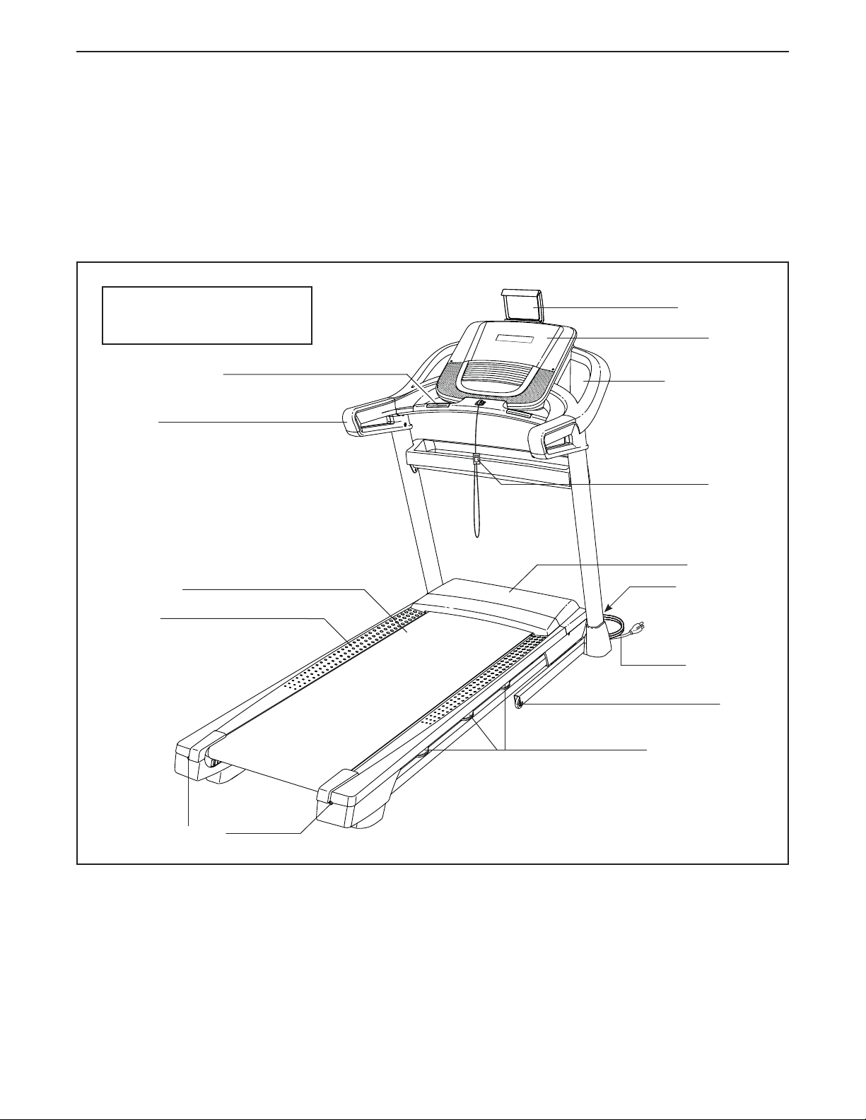
Length: 6 ft. 1 in. (185 cm)
Width: 3 ft. (91 cm)
Heart Rate Monitor
Handrail
manual. To help us assist you, note the product model
number and serial number before contacting us. The
model number and the location of the serial number
decal are shown on the front cover of this manual.
Before reading further, please familiarize yourself with
the parts that are labeled in the drawing below.
Tablet Holder
Console
Accessory Tray
Key/Clip
Walking Belt
Foot Rail
Idler Roller
Adjustment Screws
Motor Hood
Power Switch
Power Cord
Wheel
Platform Cushions
7
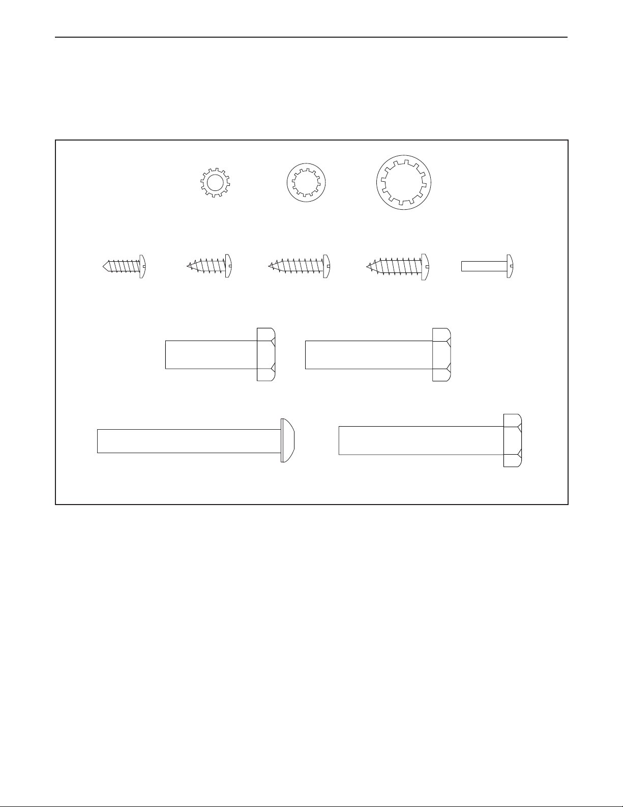
PART IDENTIFICATION CHART
Use the drawings below to identify small parts used for assembly. The number in parentheses below each drawing is the key number of the part, from the PART LIST near the end of this manual. The number following the key
number is the quantity used for assembly. Note: If a part is not in the hardware kit, check to see whether it is
preattached. Extra parts may be included.
#8 x 1/2" Silver
Screw (10)–1
#10 Star
Washer (5)–2
#8 x 1/2"
Screw (1)–12
3/8" x 1 1/4"
Screw (63)–2
5/16" x 2 1/2"
Screw (28)–4
5/16" Star
Washer (11)–14
#8 x 3/4"
Screw (2)–8
3/8" x 1 3/4" Screw (62)–2
3/8" Star
Washer (13)–8
#10 x 3/4"
Screw (9)–2
3/8" x 2 1/4" Screw (7)–4
#8 x 5/8" Machine
Screw (38)–4
8

ASSEMBLY
• Assembly requires two persons.
• Place all parts in a cleared area and remove the
packing materials. Do not dispose of the packing
materials until you fi nish all assembly steps.
• After shipping, there may be an oily substance
on the exterior of the treadmill. This is normal. If
there is an oily substance on the treadmill, wipe
it off with a soft cloth and a mild, non-abrasive
cleaner.
• Left parts are marked “L” or “Left” and right parts
are marked “R” or “Right.”
1. Go to www.nordictrackservice.com/
registration on your computer and register
your product.
• activates your warranty
• saves you time if you ever need to contact
Customer Care
• To identify small parts, see page 8.
• Assembly requires the following tools:
the included hex keys
one Phillips screwdriver
To avoid damaging parts, do not use power tools.
1
• allows us to notify you of upgrades and offers
Note: If you do not have Internet access, call
Customer Care (see the front cover of this
manual) and register your product.
9
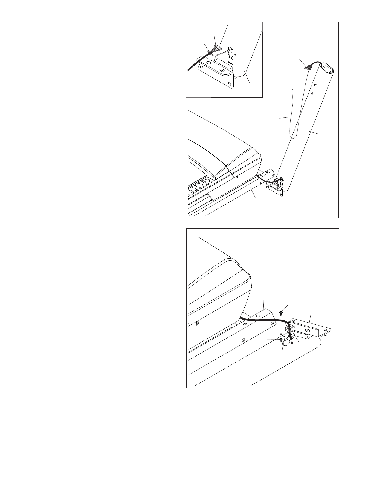
2. Make sure that the power cord is unplugged.
Remove the tie securing the Upright Wire (81) to
the front of the Base (94).
Next, identify the Right Upright (90). Have a sec-
ond person hold the Right Upright near the Base
(94).
2
81
A
81
See the inset drawing. Tie the wire tie (A) in
the Right Upright (90) securely around the end
of the Upright Wire (81). Then, insert the Upright
Wire into the lower end of the Right Upright as
you pull the other end of the wire tie through the
Right Upright.
3. Lay the Right Upright (90) near the Base (94).
Press the Grommet (77) into the square hole
(B) in the Right Upright (90). Make sure not to
pinch the ground wire.
90
A
90
94
3
If there is a screw (C) preattached to the Right
Upright (90), remove and discard it.
Then, attach the ground wire (D) to the Right
Upright (90) with a #8 x 1/2" Silver Screw (10).
94
C
10
90
77
D
B
10
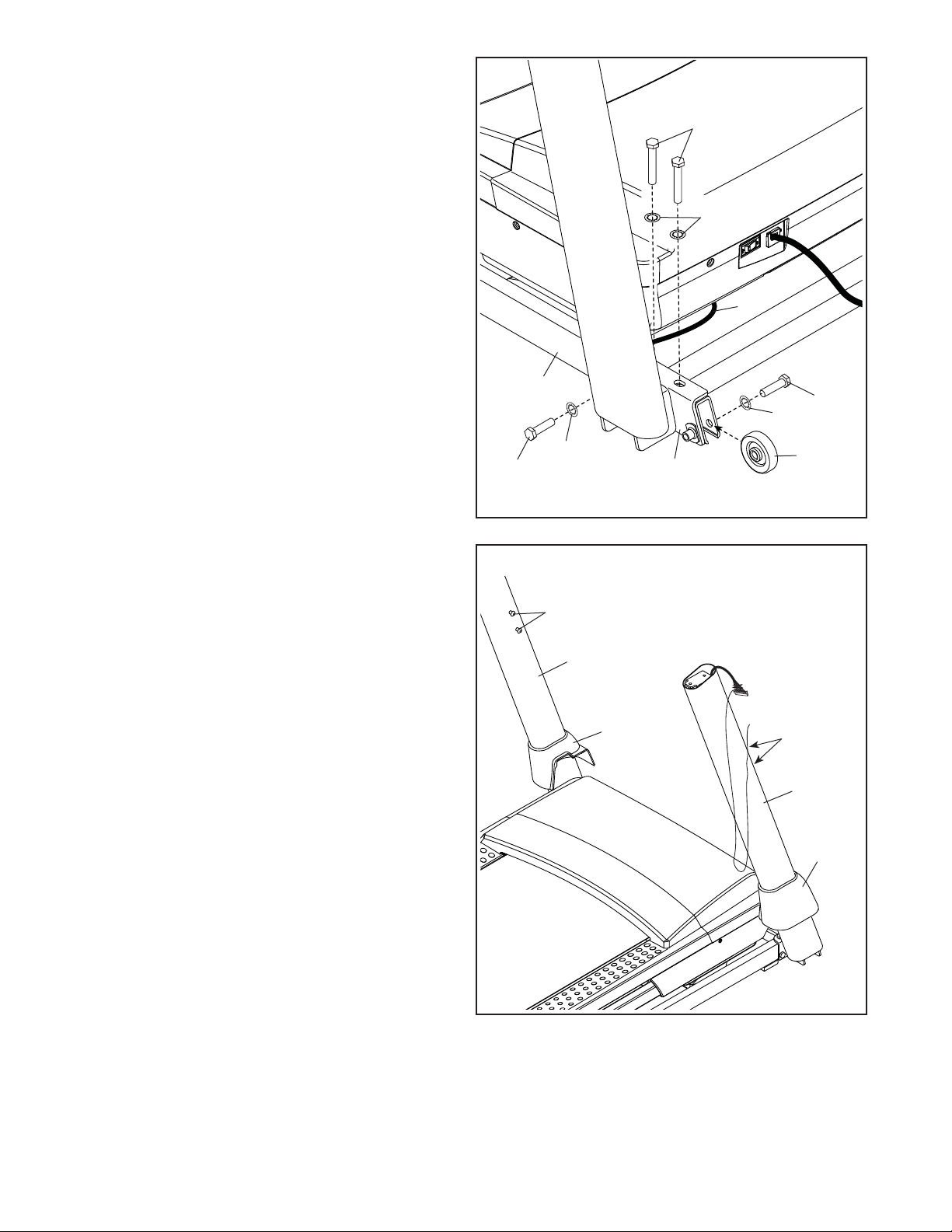
4. Hold the Right Upright (90) against the Base
(94). Make sure not to pinch the Upright Wire
(81).
Attach the Right Upright (90) and the Wheel (25)
with two 3/8" x 2 1/4" Screws (7), a 3/8" x 1 1/4"
Screw (63), a 3/8" x 1 3/4" Screw (62), and four
3/8" Star Washers (13) as shown; do not fully
tighten the Screws yet.
Attach the Left Upright (not shown) in the
same way. Note: There are no wires on the left
side.
4
7
13
81
5. Remove and save the four 5/16" x 3/4"
Screws (4).
Identify the Left and Right Base Covers (82, 83).
Slide the Left Base Cover onto the Left Upright
(89), and slide the Right Base Cover onto the
Right Upright (90). Do not press the Base
Covers into place yet.
94
13
63
5
4
89
82
90
62
13
25
4
90
11
83
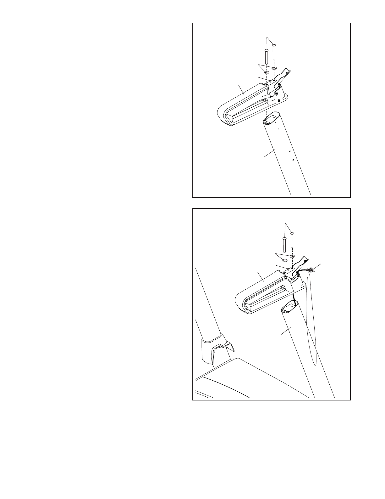
6. Identify the left handrail assembly (E). Attach
the left handrail assembly to the Left Upright
(89) with two 5/16" x 2 1/2" Screws (28) and two
5/16" Star Washers (11); do not fully tighten
the Screws yet.
Then, remove and discard the indicated
screw (F).
6
E
28
11
F
89
7. Insert the Upright Wire (81) into the bottom of
the right handrail assembly (G) and out of the
front as shown.
Attach the right handrail assembly (G) to the
Right Upright (90) with two 5/16" x 2 1/2" Screws
(28) and two 5/16" Star Washers (11). Make
sure not to pinch the Upright Wire (81); do
not fully tighten the Screws yet.
Then, remove and discard the indicated
screw (F).
7
G
11
28
F
90
81
12
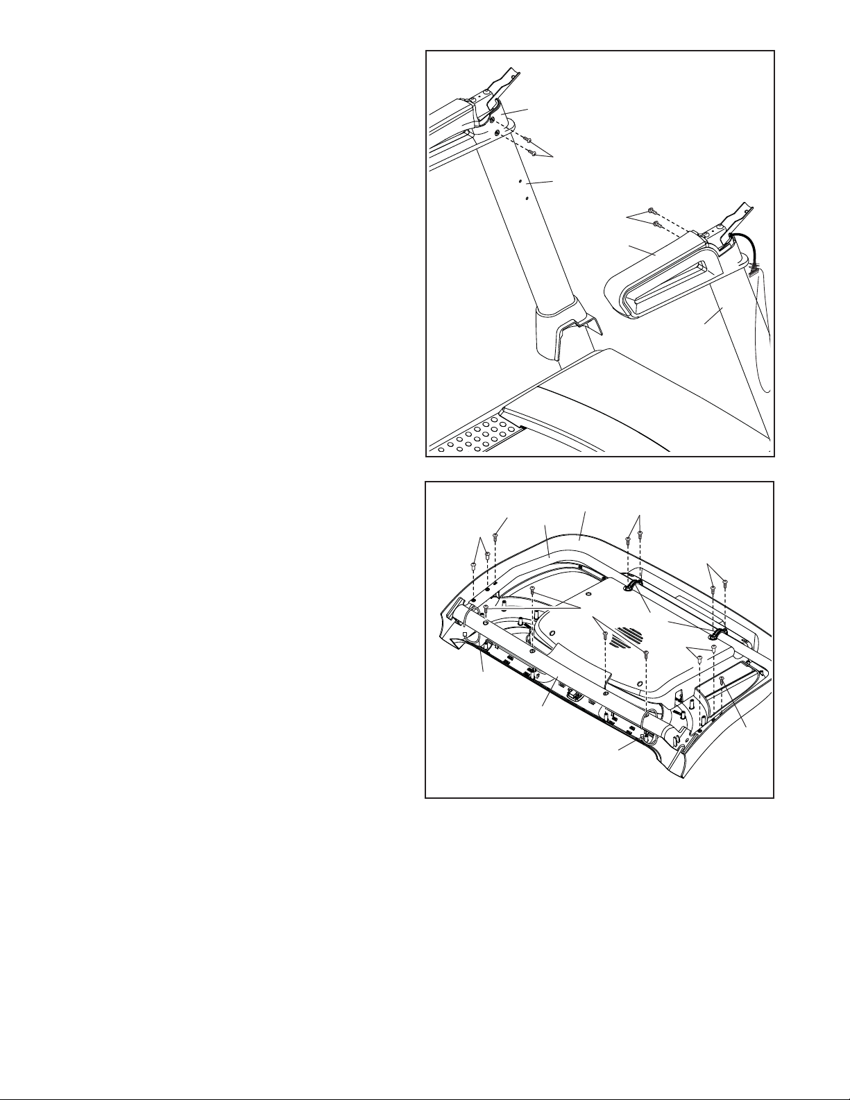
8. Tighten four #8 x 3/4" Screws (2) into the left and
right handrail assemblies (E, G) and into the Left
and Right Uprights (89, 90).
8
E
2
89
2
G
90
9. Set the Console Base (64) face down on a soft
surface to avoid scratching the Console Base.
If there are ties (H) securing the Pulse Crossbar
(93) to the Console Base, remove the ties.
Remove and discard the four indicated screws
(I). Then, remove the Pulse Crossbar (93).
Remove and save the four 5/16" x 3/4"
Screws (4) and the six #8 x 3/4" Screws (2).
Then, lift out the two Console Clamps (92) and
the Console Frame (18).
9
2
4
H
18
93
64
2
2
I
H
92
4
2
13
10. Identify the Right and Left Trays (27, 36).
Attach the Trays (27, 36) to the Console Base
(64) with eight #8 x 1/2" Screws (1); do not
overtighten the Screws.
Reattach the Console Frame (18) with the six #8
x 3/4" Screws (2) and the two Console Clamps
(92) that you removed in step 9; do not over-
tighten the Screws.
10
2
18
1
27
1
64
2
92
2
92
2
1
1
36
11. IMPORTANT: To avoid damaging the Pulse
Crossbar (93), do not use power tools and do
not overtighten the #10 x 3/4" Screws (9).
Orient the Pulse Crossbar (93) as shown. Attach
the Pulse Crossbar to the Handrails (86) with two
#10 x 3/4" Screws (9) and two #10 Star Washers
(5); start both Screws, and then tighten them.
Make sure not to pinch the Upright Wire (81).
Firmly tighten the four 5/16" x 2 1/2" Screws
(28).
11
28
9
5
93
86
9
5
86
28
81
14

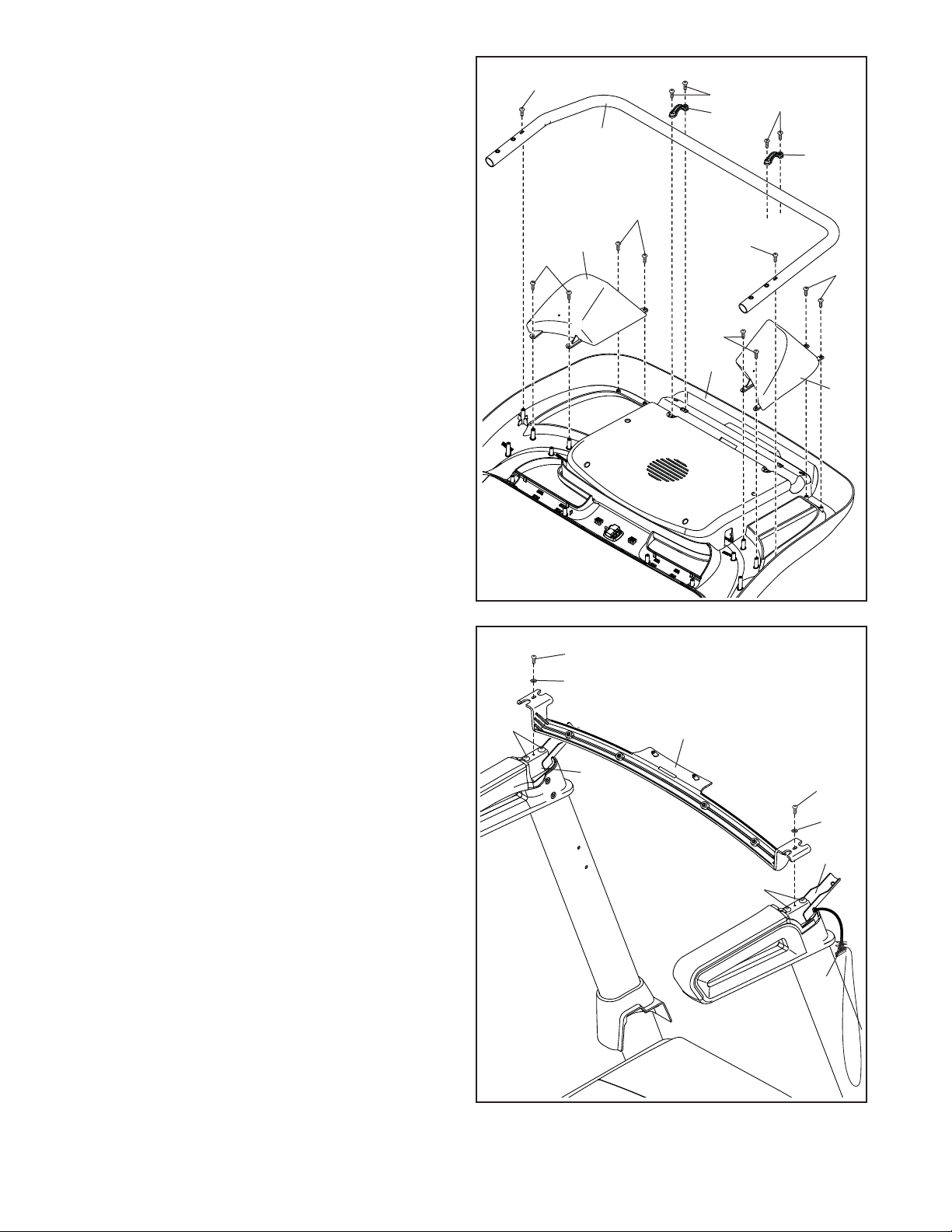
12. With the help of a second person, hold the console assembly (J) near the Handrails (86) (only
one side is shown).
Connect the ground wire (K) from the console
assembly to the Console Ground Wire (58) on
the Pulse Crossbar (93).
Next, insert the Upright Wire (81) through the
two indicated looped ties (M) on the console
assembly (J).
12
J
M
L
See the inset drawing. Connect the Upright
Wire (81) to the console wire. The connectors
should slide together easily and snap into
place. If they do not, turn one connector and
try again. IF YOU DO NOT CONNECT THE
CONNECTORS PROPERLY, THE CONSOLE
MAY BECOME DAMAGED WHEN YOU TURN
ON THE POWER. Then, remove the wire tie (A)
from the Upright Wire.
13. Set the console assembly (J) on the brackets on
the Handrails (86). Make sure not to pinch any
wires.
Attach the console assembly (J) to the brackets
on the Handrails (86) with the four 5/16" x 3/4"
Screws (4) that you removed in step 9 and four
5/16" Star Washers (11); do not fully tighten
the Screws yet.
13
86
M
81
86
K
58
93
L
A
81
J
86
Insert the excess Upright Wire (81) into the con-
sole assembly. Pull the two ties (M) tight against
the Upright Wire and cut off the ends of the ties.
15
11
4
81
11
4
 Loading...