


 Loading...
NEC NP305, NP310, NP405, NP410, NP510 Owner Manual
...Portable Projector
NP610/NP510/NP410/NP405/
NP310/NP305/NP510W/NP410W
NP610S/NP510WS
User’s Manual
NP610/NP510/NP410/NP405/NP310/NP305/NP510W/NP410W
NP610S/NP510WS
The projector’s model name indicated on the projector’s label is NP610, NP510, NP410, NP405, NP310, NP305, NP510W, NP410W, NP610S, NP510WS, NP610G, NP510G, NP410G, NP405G, NP310G, NP305G, NP510WG, NP410WG, NP610SG, and NP510WSG respectively.
All the models are referred to as NP610, NP510, NP410, NP405, NP310, NP305, NP510W, NP410W, NP610S, and NP510WS throughout the user’s manual except some of the specification pages.
The NP405 and NP305 are not distributed in North America.
1st edition, July 2009
•IBM is a trademark or registered trademark of International Business Machines Corporation.
•Macintosh, Mac OS X and PowerBook are trademarks of Apple Inc. registered in the U.S. and other countries.
•Microsoft, Windows, Windows Vista, Internet Explorer, .NET Framework and PowerPoint are either a registered trademark or trademark of Microsoft Corporation in the United States and/or other countries.
•MicroSaver is a registered trademark of Kensington Computer Products Group, a division of ACCO Brands.
•Virtual Remote Tool uses WinI2C/DDC library, © Nicomsoft Ltd.
•Other product and company names mentioned in this user’s manual may be the trademarks or registered trademarks of their respective holders.
NOTES
(1)The contents of this user’s manual may not be reprinted in part or whole without permission.
(2)The contents of this user’s manual are subject to change without notice.
(3)Great care has been taken in the preparation of this user’s manual; however, should you notice any questionable points, errors or omissions, please contact us.
(4)Notwithstanding article (3), NEC will not be responsible for any claims on loss of profit or other matters deemed to result from using the Projector.
Important Information
Safety Cautions
Precautions
Please read this manual carefully before using your NEC NP610, NP510, NP410, NP405, NP310, NP305, NP510W, NP410W, NP610S, and NP510WS projector and keep the manual handy for future reference.
CAUTION
To turn off main power, be sure to remove the plug from power outlet.
The power outlet socket should be installed as near to the equipment as possible, and should be easily accessible.
CAUTION
TO PREVENT SHOCK, DO NOT OPEN THE CABINET.
THERE ARE HIGH-VOLTAGE COMPONENTS INSIDE.
REFER SERVICING TO QUALIFIED SERVICE PERSONNEL.
This symbol warns the user that uninsulated voltage within the unit may be sufficient to cause electrical shock.Therefore, it is dangerous to make any kind of contact with any part inside of the unit.
This symbol alerts the user that important information concerning the operation and maintenance of this unit has been provided.
The information should be read carefully to avoid problems.
WARNING: TO PREVENT FIRE OR SHOCK, DO NOT EXPOSE THIS UNIT TO RAIN OR MOISTURE.
DO NOT USETHIS UNIT’S PLUGWITH AN EXTENSION CORD OR IN AN OUTLET UNLESS ALLTHE PRONGS CAN BE FULLY INSERTED.
DOC Compliance Notice (for Canada only)
This Class B digital apparatus meets all requirements of the Canadian Interference-Causing Equipment Regulations.
Machine Noise Information Regulation - 3. GPSGV,
The highest sound pressure level is less than 70 dB (A) in accordance with EN ISO 7779.
CAUTION
Avoid displaying stationary images for a prolonged period of time.
Doing so can result in these images being temporarily sustained on the surface of the LCD panel.
If this should happen, continue to use your projector. The static background from previous images will disappear.
Disposing of your used product
EU-wide legislation as implemented in each Member State requires that used electrical and electronic products carrying the mark (left) must be disposed of separately from normal household waste.This includes projectors and their electrical accessories or lamps. When you dispose of such products, please
follow the guidance of your local authority and/or ask the shop where you purchased the product. After collecting the used products, they are reused and recycled in a proper way.This effort will help us reduce the wastes as well as the negative impact such as mercury contained in a lamp to the human health and the environment at the minimum level.
The mark on the electrical and electronic products only applies to the current European Union Member
States.
i

Important Information
WARNING TO CALIFORNIA RESIDENTS:
Handling the cables supplied with this product will expose you to lead, a chemical known to the State of California to cause birth defects or other reproductive harm. WASH HANDS AFTER HANDLING.
RF Interference (for USA only)
WARNING
The Federal Communications Commission does not allow any modifications or changes to the unit EXCEPT those specified by NEC Display Solutions of America, Inc. in this manual. Failure to comply with this government regulation could void your right to operate this equipment. This equipment has been tested and found to comply with the limits for a Class B digital device, pursuant to Part 15 of the FCC Rules. These limits are designed to provide reasonable protection against harmful interference in a residential installation.This equipment generates, uses, and can radiate radio frequency energy and, if not installed and used in accordance with the instructions, may cause harmful interference to radio communications. However, there is no guarantee that interference will not occur in a particular installation.
If this equipment does cause harmful interference to radio or television reception, which can be determined by turning the equipment off and on, the user is encouraged to try to correct the interference by one or more of the following measures:
•Reorient or relocate the receiving antenna.
•Increase the separation between the equipment and receiver.
•Connect the equipment into an outlet on a circuit different from that to which the receiver is connected.
•Consult the dealer or an experienced radio / TV technician for help.
For UK only: In UK, a BS approved power cable with moulded plug has a Black (five Amps) fuse installed for use with this equipment. If a power cable is not supplied with this equipment please contact your supplier.
Important Safeguards
These safety instructions are to ensure the long life of your projector and to prevent fire and shock. Please read them carefully and heed all warnings.
 Installation
•Do not place the projector in the following conditions:
-on an unstable cart, stand, or table.
-near water, baths, or damp rooms.
-in direct sunlight, near heaters, or heat radiating appliances.
-in a dusty, smoky or steamy environment.
-on a sheet of paper or cloth, rugs or carpets.
•If you wish to have the projector installed on the ceiling:
-Do not attempt to install the projector yourself.
-The projector must be installed by qualified technicians in order to ensure proper operation and reduce the risk of bodily injury.
-In addition, the ceiling must be strong enough to support the projector and the installation must be in accordance with any local building codes.
-Please consult your dealer for more information.
ii
Important Information
WARNING
•Do not cover the lens with the lens cap or equivalent while the projector is on. Doing so can lead to melting of the cap due to the heat emitted from the light output.
•Do not place any objects, which are easily affected by heat, in front of the projector lens. Doing so could lead to the object melting from the heat that is emitted from the light output.
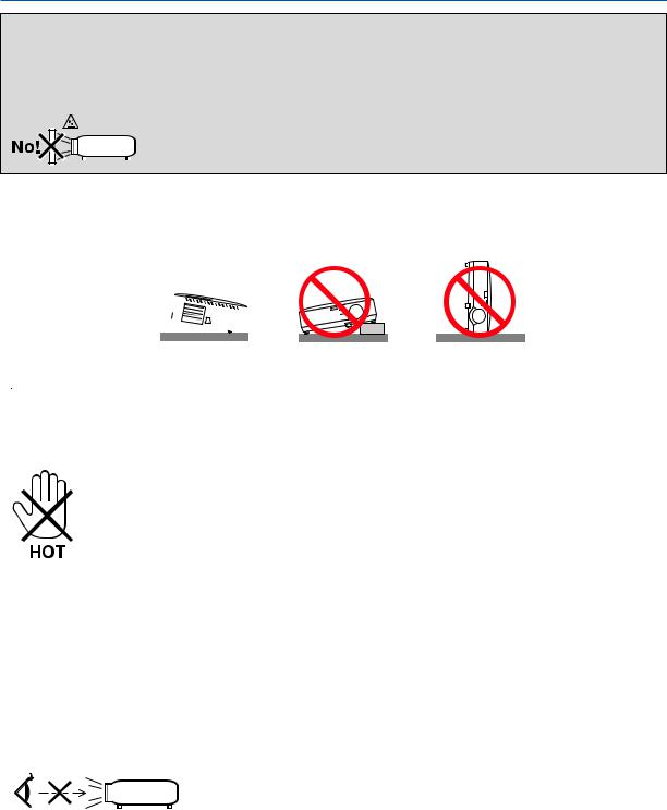
Place the projector in a horizontal position
The tilt angle of the projector should not exceed 10 degrees, nor should the projector be installed in any way other than the desktop and ceiling mount, otherwise lamp life could decrease dramatically.
10°
 Fire and Shock Precautions
•Ensure that there is sufficient ventilation and that vents are unobstructed to prevent the build-up of heat inside your projector. Allow at least 4 inches (10cm) of space between your projector and a wall.
•Do not try to touch the ventilation outlet on the left front (when seen from the front) as it can become heated while the projector is turned on and immediately after the projector is turned off.
•Prevent foreign objects such as paper clips and bits of paper from falling into your projector.Do not attempt to retrieve any objects that might fall into your projector.Do not insert any metal objects such as a wire or screwdriver into your projector. If something should fall into your projector, disconnect it immediately and have the object removed by a qualified service personnel.
•Do not place any objects on top of the projector.
•Do not touch the power plug during a thunderstorm. Doing so can cause electrical shock or fire.
•The projector is designed to operate on a power supply of 100-240V AC 50/60 Hz (NP610/NP510/NP410/NP405/ NP310/NP305/NP510W/NP410W/NP610S/NP510WS) or 200-240V AC 50/60 Hz (NP610G/NP510G/NP410G/ NP405G/NP310G/NP305G/NP510WG/ NP410WG/NP610SG/NP510WSG).Ensure that your power supply fits this requirement before attempting to use your projector.
•Do not look into the lens while the projector is on. Serious damage to your eyes could result.
•Keep any items such as magnifying glass out of the light path of the projector. The light being projected from the lens is extensive, therefore any kind of abnormal objects that can redirect light coming out of the lens, can cause unpredictable outcome such as fire or injury to the eyes.
•Do not place any objects, which are easily affected by heat, in front of a projector exhaust vent.
Doing so could lead to the object melting or getting your hands burned from the heat that is emitted from the exhaust.
iii

Important Information
•Handle the power cable carefully. A damaged or frayed power cable can cause electric shock or fire.
-Do not use any power cables than the supplied one.
-Do not bend or tug the power cable excessively.
-Do not place the power cable under the projector, or any heavy object.
-Do not cover the power cable with other soft materials such as rugs.
-Do not heat the power cable.
-Do not handle the power plug with wet hands.
•Turn off the projector, unplug the power cable and have the projector serviced by a qualified service personnel under the following conditions:
-When the power cable or plug is damaged or frayed.
-If liquid has been spilled into the projector, or if it has been exposed to rain or water.
-If the projector does not operate normally when you follow the instructions described in this user’s manual.
-If the projector has been dropped or the cabinet has been damaged.
-If the projector exhibits a distinct change in performance, indicating a need for service.
•Disconnect the power cable and any other cables before carrying the projector.
•Turn off the projector and unplug the power cable before cleaning the cabinet or replacing the lamp.
•Turn off the projector and unplug the power cable if the projector is not to be used for an extended period of time.
•When using a LAN cable (only models with the RJ-45 LAN port):
For safety, do not connect to the connector for peripheral device wiring that might have excessive voltage.
CAUTION
•Do not use the tilt-foot for purposes other than originally intended. Misuses such as gripping the tilt-foot or hanging on the wall can cause damage to the projector.
•Do not send the projector in the soft case by parcel delivery service or cargo shipment.The projector inside the soft case could be damaged.
•Select [HIGH] in Fan mode if you continue to use the projector for consecutive days. (From the menu, select [SETUP] → [OPTIONS(1)] → [FAN MODE] → [HIGH].)
•Do not try to touch the ventilation outlet on the left front (when seen from the front) as it can become heated while the projector is turned on and immediately after the projector is turned off.
•Do not turn off the AC power for 60 seconds after the lamp is turned on and while the POWER indicator is blinking green. Doing so could cause premature lamp failure.
Remote Control Precautions
•Handle the remote control carefully.
•If the remote control gets wet, wipe it dry immediately.
•Avoid excessive heat and humidity.
•Do not heat, take apart, or throw batteries into fire.
•If you will not be using the remote control for a long time, remove the batteries.
•Ensure that you have the batteries’ polarity (+/−) aligned correctly.
•Do not use new and old batteries together, or use different types of batteries together.
•Dispose of used batteries according to your local regulations.
iv

Important Information
Note for US Residents
The lamp in this product contains mercury. Please dispose according to Local, State or Federal Laws.
Lamp Replacement
•To replace the lamp, follow all instructions provided on page 84.
•Be sure to replace the lamp when the message [THE LAMP HAS REACHED THE END OF ITS USABLE LIFE. PLEASE REPLACE THE LAMP.] appears. If you continue to use the lamp after the lamp has reached the end of its usable life, the lamp bulb may shatter, and pieces of glass may be scattered in the lamp case. Do not touch them as the pieces of glass may cause injury.
If this happens, contact your dealer for lamp replacement.
A Lamp Characteristic
The projector has a high-pressure mercury lamp as a light source.
A lamp has a characteristic that its brightness gradually decreases with age. Also repeatedly turning the lamp on and off will increase the possibility of its lower brightness.
 CAUTION:
•DO NOT TOUCH THE LAMP immediately after it has been used. It will be extremely hot. Turn the projector off and then disconnect the power cable. Allow at least one hour for the lamp to cool before handling.
•When removing the lamp from a ceiling-mounted projector, make sure that no one is under the projector. Glass fragments could fall if the lamp has been burned out.
About High Altitude mode
•Set [FAN MODE] to [HIGH ALTITUDE] when using the projector at altitudes approximately 5500 feet/1600 meters or higher.
Using the projector at altitudes approximately 5500 feet/1600 meters or higher without setting to [HIGH ALTITUDE] can cause the projector to overheat and the protector could shut down. If this happens, wait a couple minutes and turn on the projector.
•Using the projector at altitudes less than approximately 5500 feet/1600 meters and setting to [HIGH ALTITUDE] can cause the lamp to overcool, causing the image to flicker. Switch [FAN MODE] to [AUTO].
•Using the projector at altitudes approximately 5500 feet/1600 meters or higher can shorten the life of optical components such as the lamp.
About Copyright of original projected pictures:
Please note that using this projector for the purpose of commercial gain or the attraction of public attention in a venue such as a coffee shop or hotel and employing compression or expansion of the screen image with the following functions may raise concern about the infringement of copyrights which are protected by copyright law.
[ASPECT RATIO], [KEYSTONE], Magnifying feature and other similar features.
v

Table of Contents
Important Information............................................................................................ |
i |
1. Introduction........................................................................................................... |
1 |
1 What’s in the Box?.......................................................................................................... |
1 |
Introduction to the Projector........................................................................................... |
2 |
Congratulations on Your Purchase of the Projector.................................................. |
2 |
Features you’ll enjoy:................................................................................................ |
2 |
About this user’s manual.......................................................................................... |
3 |
Part Names of the Projector........................................................................................... |
5 |
Front/Top................................................................................................................... |
5 |
Rear.......................................................................................................................... |
6 |
Top Features............................................................................................................. |
7 |
Terminal Panel Features........................................................................................... |
8 |
Part Names of the Remote Control................................................................................ |
9 |
Battery Installation.................................................................................................. |
10 |
Remote Control Precautions.................................................................................. |
10 |
Operating Range for Wireless Remote Control...................................................... |
10 |
2. Installation and Connections.................................................................... |
11 |
Setting Up the Screen and the Projector...................................................................... |
11 |
Selecting a Location............................................................................................... |
11 |
Throw Distance and Screen Size........................................................................... |
15 |
Making Connections..................................................................................................... |
17 |
Enabling the computer’s external display............................................................... |
17 |
Connecting Your PC or Macintosh Computer......................................................... |
17 |
When Viewing a DVI Digital Signal (except NP405 and NP305)............................ |
19 |
Using Two Analog COMPUTER Inputs Simultaneously......................................... |
20 |
Connecting an External Monitor............................................................................. |
21 |
Connecting Your DVD Player with Component Output........................................... |
22 |
Connecting Your VCR............................................................................................. |
23 |
Connecting to a Network (except NP405 and NP305)........................................... |
24 |
Connecting the Supplied Power Cable................................................................... |
25 |
3. Projecting an Image (Basic Operation)............................................... |
26 |
Turning on the Projector............................................................................................... |
26 |
Note on Startup screen (Menu Language Select screen)...................................... |
28 |
Selecting a Source....................................................................................................... |
29 |
Selecting the computer or video source................................................................. |
29 |
Adjusting the Picture Size and Position........................................................................ |
30 |
Adjust the Tilt Foot.................................................................................................. |
31 |
Zoom...................................................................................................................... |
32 |
Adjusting from the menu......................................................................................... |
32 |
Focus...................................................................................................................... |
33 |
Correcting Keystone Distortion.................................................................................... |
34 |
Correcting Keystone Distortion............................................................................... |
34 |
Adjusting with buttons on the cabinet..................................................................... |
34 |
Adjusting from the menu......................................................................................... |
35 |
Adjusting with the Auto Keystone Function............................................................ |
36 |
vi

Table of Contents |
|
Optimizing Computer Signal Automatically.................................................................. |
37 |
Adjusting the Image Using Auto Adjust.................................................................. |
37 |
Turning Up or Down Volume......................................................................................... |
37 |
7 Turning off the Projector............................................................................................... |
38 |
After Use...................................................................................................................... |
39 |
4. Convenient Features...................................................................................... |
40 |
1 Turning off the Image and Sound................................................................................. |
40 |
2 Freezing a Picture........................................................................................................ |
40 |
Enlarging a Picture....................................................................................................... |
40 |
Changing Eco Mode..................................................................................................... |
41 |
5 Checking Energy-Saving Effect [CARBON METER].................................................... |
42 |
6 Preventing the Unauthorized Use of the Projector [SECURITY]....................................... |
43 |
7 Using the Optional Remote Mouse Receiver (NP01MR)............................................. |
46 |
8 Network Setting by Using an HTTP Browser (except NP405 and NP305).................. |
48 |
9 Using the VGA Signal Cable to Operate the Projector (Virtual Remote)...................... |
51 |
5. Using On-Screen Menu................................................................................ |
56 |
Using the Menus.......................................................................................................... |
56 |
2 Menu Elements............................................................................................................ |
57 |
3 List of Menu Items........................................................................................................ |
58 |
4 Menu Descriptions & Functions [SOURCE]................................................................. |
60 |
5 Menu Descriptions & Functions [ADJUST].................................................................. |
61 |
6 Menu Descriptions & Functions [SETUP].................................................................... |
68 |
7 Menu Descriptions & Functions [INFO.]....................................................................... |
78 |
8 Menu Descriptions & Functions [RESET].................................................................... |
80 |
6. Maintenance....................................................................................................... |
81 |
Cleaning or Replacing the Filters................................................................................. |
81 |
2 Cleaning the Cabinet and the Lens.............................................................................. |
83 |
Replacing the Lamp..................................................................................................... |
84 |
7. Appendix............................................................................................................... |
87 |
Troubleshooting............................................................................................................ |
87 |
Indicator Messages................................................................................................ |
87 |
Specifications............................................................................................................... |
90 |
Cabinet Dimensions..................................................................................................... |
94 |
Pin Assignments of D-Sub COMPUTER Input Connector........................................... |
96 |
Mini D-Sub 15 Pin Connector................................................................................. |
96 |
Compatible Input Signal List........................................................................................ |
97 |
PC Control Codes and Cable Connection.................................................................... |
98 |
PC Control Codes................................................................................................... |
98 |
Cable Connection................................................................................................... |
98 |
PC Control Connector (D-SUB 9P)........................................................................ |
98 |
Troubleshooting Check List.......................................................................................... |
99 |
TravelCare Guide........................................................................................................ |
101 |
vii
1. Introduction
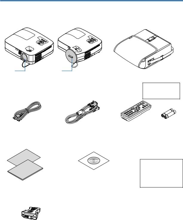
1 What’s in the Box?
Make sure your box contains everything listed. If any pieces are missing, contact your dealer. Please save the original box and packing materials if you ever need to ship your projector.
Projector
Lens cap |
Lens cap |
|
|
|
|
(24F44681) |
(24FU0691) |
|
Soft case |
|
|
|
|
|
(24BS7582) |
|
|
NP610/NP510/NP410/ |
NP610S/NP510WS |
NP610/NP510/NP410/ |
The NP405, NP305, |
||
NP405/NP310/NP305/ |
|
NP310/NP510W/ |
NP610S, and NP510WS |
||
NP510W/NP410W |
|
NP410W |
|
do not come with a soft |
|
|
|
|
|
case. |
|
|
|
|
1 |
|
|
|
|
|
2 |
|
|
Power cable |
VGA signal cable |
|
Remote control |
Batteries (AAA × 2) |
|
(US: 7N080235) |
(7N520073/7N520052) |
(7N900901) |
|
|
|
(EU: 7N080021) |
|
|
|
|
|
•Important Infomation (For North America:
7N8P9731) (For Other countries than North America: 7N8P9731 and 7N8P9741)
•Quick Setup Guide (7N8P9721)
DVI to VGA adapter (7N960234) The NP405 and NP305 do not come with the DVI to VGA adapter.
NEC Projector CD-ROM User’s manual (PDF) and the utility software “Virtual
Remote Tool” (7N951361)
For North America only
Registration card Limited warranty
For customers in Europe:
Youwillfind ourcurrentvalidGuarantee Policy on our Web Site: www.nec-display-solutions.com
Unless otherwise described in the user’s manual, the drawings for the projector cabinet show examples of the NP610.
1
1. Introduction
Introduction to the Projector
This section introduces you to your new projector and describes the features and controls.
Congratulations on Your Purchase of the Projector
This projector is one of the very best projectors available today. The projector enables you to project precise images up to 300 inches (110 inches on NP610S; 104 inches on NP510WS) across (measured diagonally) from your PC or Macintosh computer (desktop or notebook), VCR, DVD player, or document camera.
You can use the projector on a tabletop or cart, you can use the projector to project images from behind the screen, and the projector can be permanently mounted on a ceiling*1.The remote control can be used wirelessly.
*1 Do not attempt to mount the projector on a ceiling yourself.
The projector must be installed by qualified technicians in order to ensure proper operation and reduce the risk of bodily injury.
In addition, the ceiling must be strong enough to support the projector and the installation must be in accordance with any local building codes. Please consult your dealer for more information.
Features you’ll enjoy:
•Quick start & Quick Power Off
Less than 4 seconds* after turning on the power, the projector is ready to display PC or video images.
* The quick start time is only when [STANDBY MODE] is set to [NORMAL] in the on-screen message.
The projector can be put away immediately after the projector is powered down. No cool down period is required after the projector is turned off from the remote control or cabinet control panel.
•Direct Power Off
The projector has a feature called “Direct Power Off”.This feature allows the projector to be turned off (even when projecting an image) by using the Main Power Switch or disconnecting the AC power supply.
To turn off the AC power supply when the projector is powered on, use a power strip equipped with a switch and a breaker.
•Less than 1W in standby condition with energy saving technology
Selecting [POWER-SAVING] for [STANDBY MODE] from the menu can put the projector in power-saving mode that consumes only 0.6W (100-130V AC)/0.7W (200-240V AC).
•Carbon Meter
This feature will show energy-saving effect in terms of CO2 emission reduction (kg) when the projector’s [ECO MODE] is set to [ON].
The amount of CO2 emission reduction will be displayed in the confirmation message at the time of power-off and in the INFO of the on-screen menu.
•7W built-in speaker for an integrated audio solution
Powerful 7 watt speaker provides volume need for large rooms.
•Virtual Remote function
The Virtual Remote function allows power On/Off and source selection of the projector from your PC by using the supplied VGA signal cable.The utility software “Virtual Remote Tool” exclusively for the projector is required to be installed from the accompanying NEC Projector CD-ROM onto your computer.
An accompanying NEC Projector CD-ROM includes the utility software “Virtual Remote Tool” exclusively for the projector and user’s manuals in PDF format.
•Short throw distances (NP610S/NP510WS)
Short focal lenses provide for a larger image using a shorter throw distance when compared to a typical projector lens.
2

1. Introduction
•A variety of input ports and a comprehensive array of system control interfaces
This projector supports input signals on the following ports: DVI-I connector (DVI-I 29 Pin) with HDCP compatible, 15pin D-Sub, composite and S-video.
•AUTO POWER ON and AUTO POWER OFF features
The AUTO POWER ON(AC), AUTO POWER ON(COMP1), AUTO POWER OFF, and OFFTIMER features eliminate the need to always use the POWER button on the remote control or projector cabinet.
•Preventing unauthorized use of the projector
Enhanced smart security settings for keyword protection, cabinet control panel lock, security slot, and security chain opening to help prevent unauthorized access, adjustments and theft deterrence.
•The optional remote control (NP02RC) allows you to assign a CONTROL ID to the projector
Multiple projectors can be operated separately and independently with the same single remote control by assigning an ID number to each projector.
•Integrated RJ-45 connector for wired networking capability (except NP405/NP305)
An RJ-45 connector is equipped as standard feature.
•Auto vertical keystone correction
Auto Keystone feature allows the projector to detect its tilt and correct vertical distortion automatically.
•LCD projector with high resolution and high brightness
High resolution display - up to UXGA compatible, XGA (NP610/NP510/NP410/NP405/NP310/NP305/NP610S)/ WXGA (NP510W/NP410W/NP510WS) native resolution.
•Six picture preset modes for user adjustable picture and color settings
Each picture preset mode can be customized and memorized according to your preference.
•PC Control Port
You can control the projector with a PC or control system using the PC Control port.
•Optional remote mouse receiver
You can use the supplied wireless remote control and the optional remote mouse receiver to operate your PC mouse from across the room. The optional remote mouse receiver (NP01MR) supports almost any PC using a USB connection.
About this user’s manual
The fastest way to get started is to take your time and do everything right the first time. Take a few minutes now to review the user’s manual.This may save you time later on. At the beginning of each section of the manual you’ll find an overview. If the section doesn’t apply, you can skip it.
3
1. Introduction
Comparative Table of Main Features
The main features vary depending on the model as follows.
|
|
|
|
|
|
|
|
|
|
|
Short-Throw |
Wide Panel & |
|
|
|
|
Standard Models |
|
|
Wide Panel Model |
Short-Throw |
||||
|
|
|
|
|
|
Model |
||||||
|
|
|
|
|
|
|
|
|
|
|
Model |
|
|
|
|
|
|
|
|
|
|
|
|
|
|
|
NP610 |
NP510 |
|
NP410 |
NP405 |
|
NP310 |
NP305 |
NP510W |
NP410W |
NP610S |
NP510WS |
Native Aspect |
|
|
|
|
|
|
|
|
|
|
|
|
Ratio |
|
|
|
|
|
|
|
|
|
|
|
|
(→ page 90, 92) |
|
|
|
Standard |
|
|
Wide |
Standard |
Wide |
|||
|
|
|
|
|
|
|||||||
Native Resolution |
|
|
|
|
|
|
|
|
WXGA |
XGA |
WXGA |
|
(dots x lines*1) |
|
|
XGA (1024 x 768) |
|
|
|||||||
|
|
|
|
(1280 x 800) |
(1024 x 768) |
(1280 x 800) |
||||||
(→ page 90, 92) |
|
|
|
|
|
|
|
|
||||
|
|
|
|
|
|
|
|
|
|
|
|
|
Screen Size |
|
|
|
|
21"–300" |
|
|
|
60"–110" |
57"–104" |
||
(→ page 90, 92) |
|
|
|
|
|
|
|
|||||
|
|
|
|
|
|
|
|
|
|
|
|
|
Throw Distance |
|
30–444 inches/0.7–11.3 m |
|
31–470 inches/ |
35"–66"/ |
36"–66"/ |
||||||
(→ page 90, 92) |
|
|
0.8–11.9 m |
0.9 m–1.7 m |
0.9 m–1.7 m |
|||||||
|
|
|
|
|
|
|
|
|||||
Light output*2*3 |
|
|
|
|
|
|
|
|
|
|
|
|
in OFF for ECO |
3500 |
3000 |
|
2600 lumens |
|
2200 lumens |
3000 |
2600 |
2600 lumens |
2100 lumens |
||
MODE |
lumens |
lumens |
|
lumens |
lumens |
|||||||
|
|
|
|
|
|
|
||||||
(→ page 90, 92) |
|
|
|
|
|
|
|
|
|
|
|
|
Wired LAN |
|
RJ-45 |
|
|
— |
|
RJ-45 |
— |
|
|
RJ-45 |
|
(→ page 24, 48) |
|
|
|
|
|
|
|
|||||
|
|
|
|
|
|
|
|
|
|
|
|
|
Zoom |
|
|
|
Using the manual zoom lever |
|
|
Using the [DIGITAL ZOOM] function |
|||||
(→ page 32) |
|
|
|
|
|
from the menu |
||||||
|
|
|
|
|
|
|
|
|
|
|||
Focus |
|
|
|
Using the manual focus ring |
|
|
Using the manual focus lever |
|||||
(→ page 33) |
|
|
|
|
|
|||||||
|
|
|
|
|
|
|
|
|
|
|
|
|
Lamp Replace- |
|
|
|
|
|
|
|
|
|
|
|
|
ment Time (aver- |
|
|
|
4000 (H) in OFF for ECO MODE /5000 (H) in ON for ECO MODE |
|
|||||||
age) |
|
|
|
|
||||||||
|
|
|
|
|
|
|
|
|
|
|
|
|
(→ page 78) |
|
|
|
|
|
|
|
|
|
|
|
|
For further details on the specifications, see page 90. *1 Effective pixels are more than 99.99%.
*2 This is the light output value (lumens) when the [PRESET] mode is set to [HIGH-BRIGHT]. If any other mode is selected as the [PRESET] mode, the light output value may drop slightly.
*3 Compliance with ISO21118-2005
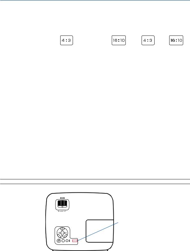
TIP: The model name is located on the cabinet.
FOCUS
E NTER
Model name
MENU
|
EXIT |
|
LAMP |
|
STATUS |
SOURCE |
AUTO ADJ. |
4
1. Introduction
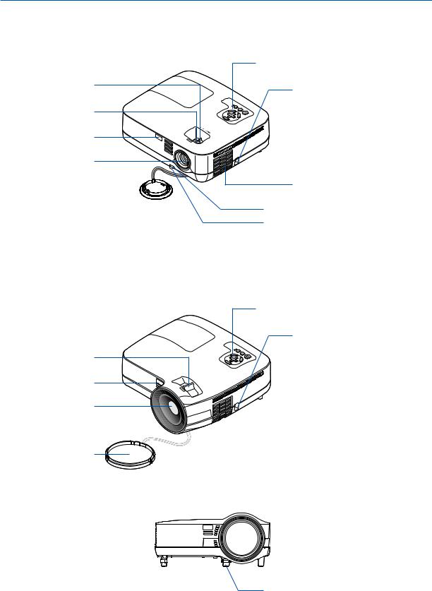
Part Names of the Projector
Front/Top
NP610/NP510/NP410/NP405/NP310/NP305/NP510W/NP410W
Zoom Lever (→ page 32)
Focus Ring
(→ page 33)
Remote sensor (→ page 10)
US |
CFO |
Controls (→ page 7)
Security chain opening
Attach an anti-theft device.
The security chain opening accepts security wires or chains up to 0.18 inch/ 4.6 mm in diameter.
Lens
Lens Cap 

 Built-in Security Slot (
  )*
)*
Ventilation (inlet) / Filter Cover (→ page 81)
Adjustable Tilt Foot Lever (→ page 31)
Adjustable Tilt Foot (→ page 31)
*This security slot supports the MicroSaver ® Security System.
NP610S/NP510WS
Focus Lever (→ page 33)
Remote sensor (→ page 10)
Lens
Lens Cap
Controls (→ page 7)
Security chain opening Attach an anti-theft device.
The security chain opening accepts security wires or chains up to 0.18 inch/ 4.6 mm in diameter.
 Built-in Security Slot (
  )*
)*
 Ventilation (inlet) / Filter Cover (→ page 81)
*This security slot supports the MicroSaver ® Security System.
 Adjustable Tilt Foot Lever (→ page 31)
Adjustable Tilt Foot (→ page 31)
5
1. Introduction
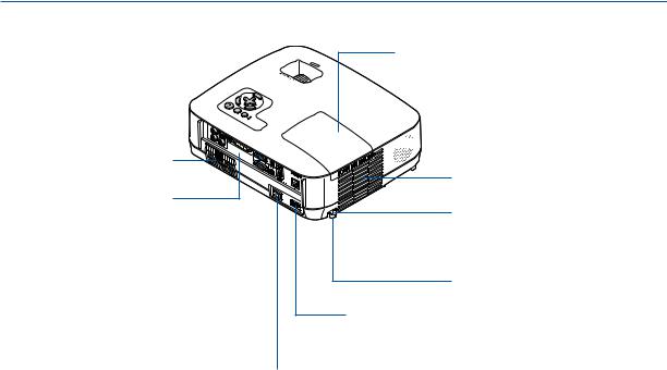
Rear
Ventilation (inlet) / Filter Cover
(→ page 81)
Terminal Panel (→ page 8)
Lamp Cover (→ page 85)


 Monaural Speaker (7W)
Ventilation (outlet)
Heated air is exhausted from here.
Spacer (black rubber)
To fine-adjust the height of the rear foot, remove the spacer and rotate the rear foot to the desired height.
Rear Foot (→ page 31)
AC Input
Connect the supplied power cable’s two-pin plug here, and plug the other end into an active wall outlet. (→ page 25)
Main Power Switch
When you plug the supplied power cable into an active wall outlet and turn on the Main Power, the POWER indicator turns orange and the projector is in standby mode.
(→ page 26, 38)
6
1. Introduction
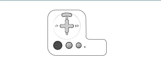
Top Features
7
8
9 


 10
10
 LAMP
LAMP
 STATUS
SOURCE AUTO ADJ.
1 2 5 6
1. (POWER) Button (→ page 27, 38)
2.POWER Indicator (→ page 26, 38, 87)
3.STATUS Indicator (→ page 87)
4.LAMP Indicator (→ page 84, 87)
5.SOURCE Button (→ page 29)
6.AUTO ADJ. Button (→ page 37)
7.MENU Button (→ page 56)
8./ Volume Buttons / Keystone Buttons
(→ page 34, 37)
9.ENTER Button (→ page 56)
10.EXIT Button (→ page 56)
4
3
7
1. Introduction
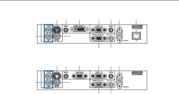
Terminal Panel Features
NP610/NP510/NP410/NP310/NP510W/NP410W/NP610S/NP510WS
6 |
3 |
2 |
1 |
3 |
9 |
10 |
8 |
7 |
5 4
NP405/NP305
6 |
3 |
2 |
1 |
3 |
9 |
8 |
7 |
5 4
1.COMPUTER 1 IN/ Component Input Connector (Mini D-Sub 15 Pin) (→ page 17, 20, 22)
2.COMPUTER 2 (DVI-I) IN Connector (29 Pin) (HDCP compatible) (→ page 19, 20)
(NP610/NP510/NP410/NP310/NP510W/NP410W/
NP610S/NP510WS)
COMPUTER 2 IN / Component Input Connector (Mini D-Sub 15 Pin) (→ page 17, 20, 22)
(NP405/NP305)
3.AUDIO IN Mini Jack (Stereo Mini)
(→ page 17, 19, 22)
4.AUDIO OUT Mini Jack (Stereo Mini) (→ page 21)
5.MONITOR OUT (COMP 1) Connector (Mini D-Sub 15 Pin) (→ page 21)
6.S-VIDEO IN Connector (Mini DIN 4 Pin)
(→ page 23)
7.VIDEO IN Connector (RCA) (→ page 23)
8.AUDIO Input Jacks L/R (RCA) (→ page 23)
9.PC CONTROL [PC CONTROL] Port (D-Sub 9 Pin)
(→ page 98)
Use this port to connect a PC or control system.
This enables you to control the projector using serial communication protocol. If you are writing your own program, typical PC control codes are on page 98.
10.LAN Port (RJ-45) (→ page 24)
(not available on NP405/NP305)
8
1. Introduction
Part Names of the Remote Control
3
4
7
OFF |
ON |
POWER |
|
MAGNIFY AV-MUTE |
PAGE |
|
UP |
|
DOWN |
MENU |
|
1
2
6
5
8
9
11
13
14
19
17
ENTER |
EXIT |
L-CLICK |
R-CLICK |
|
MOUSE |
VIDEO |
COMPUTER AUTO ADJ. |
1 |
S-VIDEO |
ECO MODE |
2
VOLUME ASPECT HELP
PICTURE FREEZE
10
12
16
15
18
21
22
20
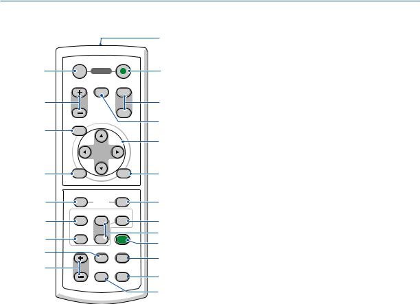
12.MOUSE R-CLICK Button*
(→ page 46, 47)
1.Infrared Transmitter
(→ page 10)
2.POWER ON Button
(→ page 27)
3.POWER OFF Button
(→ page 38)
4.MAGNIFY (+)(−) Button
(→ page 40)
5.AV-MUTE Button
(→ page 40)
6.PAGE UP/DOWN Button*
(→ page 46, 47)
7.MENU Button
(→ page 56)
8.SELECT Button (→ page 56)
9.ENTER Button (→ page 56)
10.EXIT Button (→ page 56)
11.MOUSE L-CLICK Button*
(→ page 46, 47)
13.VIDEO Button
(→ page 29)
14.S-VIDEO Button
(→ page 29)
15.COMPUTER 1/2 Button
(→ page 29)
16.AUTO ADJ. Button
(→ page 37)
17.VOLUME (+)(−) Button
(→ page 37)
18.ECO MODE Button (→ page 41)
19.ASPECT Button
(→ page 66)
20.PICTURE Button
(→ page 61, 62)
21.HELP Button
(→ page 78)
22.FREEZE Button
(→ page 40)
*The PAGE UP/DOWN, MOUSE L-CLICK and MOUSE R-CLICK buttons work only when the optional remote mouse receiver is connected with your computer.
9
|
|
1. Introduction |
Battery Installation |
|
|
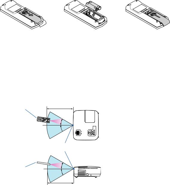
1 Press firmly and slide the battery |
2 Install new batteries (AAA).Ensure |
3 Slip the cover back over the bat- |
cover off. |
that you have the batteries’ polarity |
teries until it snaps into place. Do |
|
(+/−) aligned correctly. |
not mix different types of batteries |
|
|
or new and old batteries. |
Remote Control Precautions
•Handle the remote control carefully.
•If the remote control gets wet, wipe it dry immediately.
•Avoid excessive heat and humidity.
•Do not heat, take apart, or throw batteries into fire.
•If you will not be using the remote control for a long time, remove the batteries.
•Ensure that you have the batteries’ polarity (+/−) aligned correctly.
•Do not use new and old batteries together, or use different types of batteries together.
•Dispose of used batteries according to your local regulations.
Operating Range for Wireless Remote Control
7 m/22 feet
Remote control
30°
30°
Remote sensor on projector cabinet
Remote control |
30° |
|
|
|
30° |
7 m/22 feet
•The infrared signal operates by line-of-sight up to a distance of about 22 feet/7 m and within a 60-degree angle of the remote sensor on the projector cabinet.
•The projector will not respond if there are objects between the remote control and the sensor, or if strong light falls on the sensor. Weak batteries will also prevent the remote control from properly operating the projector.
10

2. Installation and Connections
This section describes how to set up your projector and how to connect video and audio sources. Your projector is simple to set up and use. But before you get started, you must first:
z Set up a screen and the projector.
x Connect your computer or video equipment to the projector.
(→ page 17, 19, 20, 21, 22, 23, 24)
c Connect the supplied power cable.
(→ page 25)
NOTE: Ensure that the power cable and any other cables are disconnected before moving the projector. When moving the projector or when it is not in use, cover the lens with the lens cap.
To the wall outlet.
Setting Up the Screen and the Projector
Selecting a Location
NOTE: Throw distances vary depending on the model.
[NP610/NP510/NP410/NP405/NP310/NP305]
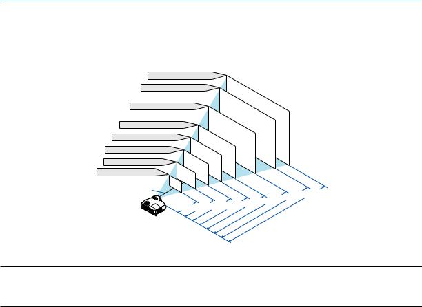
The further your projector is from the screen or wall, the larger the image. The minimum size the image can be is approximately 21" (0.53 m) measured diagonally when the projector is roughly 30 inches (0.8 m) from the wall or screen. The largest the image can be is 300" (7.6 m) when the projector is about 407 inches (10.3 m) from the wall or screen.
Screen Size (Unit: cm/inch)
609.6(W) 457.2(H) / 240(W) 180(H)
487.7(W) 365.8(H) / 192(W) 144(H) |
|
300" |
|
||||||||
406.4(W) 304.8(H) / 160(W) 120(H) |
240" |
|
|
||||||||
200" |
|
|
|
|
|||||||
365.8(W) 274.3(H) / 144(W) 108(H) |
|
|
|
|
|
||||||
180" |
|
|
|
|
|||||||
304.8(W) 228.6(H) / 120(W) 90(H) |
|
|
|
|
|||||||
150" |
|
|
|
|
|||||||
243.8(W) 182.9(H) / 96(W) 72(H) |
|
|
|
|
|
|
|||||
|
120" |
|
|
|
|
|
|||||
203.2(W) 152.4(H) / 80(W) 60(H) |
|
|
|
|
|
|
|||||
100" |
|
|
|
|
|
|
|||||
162.6(W) 121.9(H) / 64(W) 48(H) |
|
|
|
|
|
|
|
||||
80" |
|
|
|
|
|
|
|
||||
121.9(W) 91.4(H) / 48(W) 36(H) |
|
|
|
|
|
|
|
|
|||
81.3(W) 61.0(H) / 32(W) 24(H) |
|
|
60" |
|
|
|
|
|
|
|
|
|
40" |
|
|
|
|
|
|
|
|
||
61.0(W) 45.7(H) / 24(W) 18(H) |
|
|
|
|
|
|
|
|
|
||
|
|
|
|
|
|
|
|
|
|
|
|
42.7(W) 32(H) / 17(W) 13(H) |
30" |
|
|
|
|
|
|
|
|
|
|
Lens center |
21" |
|
|
|
|
|
|
|
|
|
|
|
|
|
|
|
|
|
|
|
|
" |
|
|
|
1 " |
|
|
|
|
|
|
|
||
|
|
|
|
|
" |
" |
41/162 |
||||
|
.8/" |
|
|
" |
|
|
|
||||
|
0 |
|
40. |
|
2 |
|
|
|
|
|
|
|
30 |
" |
27/10734/135 |
|
. |
|
|||||
|
.0/ |
.0/81 . |
|
|
|
|
|||||
|
|
|
13/53 |
. |
|
|
|
|
|||
|
|
|
|
|
|
|
|
|
|
||
Screen Size
|
|
|
|
|
. |
|
|
" |
" |
|
|
|
|
|
|
3/325 |
3/407 |
||
|
|
.2/244 |
|
" |
|
10 |
|||
|
|
69/271 |
8 |
||||||
|
" |
" |
|
|
. . |
||||
51/203 |
|
|
|
|
|
||||
6 |
|
|
|
|
|
|
|
||
. |
|
|
|
|
|
|
|
|
|
|
|
|
|
|
|
|
|
m/inch) |
|
|
|
|
|
|
(Unit: |
|
|||
|
|
Distance |
|
|
|
|
|||
TIP:
•The distances are indicated by intermediate values between tele and wide. Use as a rule of thumb.
•The Zoom lever adjusts the image size by up to +/−10%.
•For more details on throw distance, see page 15.
11
2. Installation and Connections
[NP510W/NP410W]
The further your projector is from the screen or wall, the larger the image. The minimum size the image can be is approximately 21" (0.53 m) measured diagonally when the projector is roughly 31 inches (0.8 m) from the wall or screen. The largest the image can be is 300" (7.6 m) when the projector is about 431 inches (11.0 m) from the wall or screen.
Screen Size (Unit: cm/inch)
646.2(W) 403.9(H) / 254(W) 159(H)
516.9(W) 323.1(H) / 204(W) 127(H) |
|
300" |
|
||||||||
430.8(W) 269.2(H) / 170(W) 106(H) |
240" |
|
|
||||||||
387.7(W) 242.3(H) / 153(W) 95(H) |
|
200" |
|
|
|
|
|||||
180" |
|
|
|
|
|||||||
323.1(W) 201.9(H) / 127(W) 79(H) |
|
|
|
|
|||||||
258.5(W) 161.5(H) / 102(W) 64(H) |
|
|
150" |
|
|
|
|
||||
|
120" |
|
|
|
|
|
|||||
215.4(W) 134.6(H) / 85(W) 53(H) |
|
|
|
|
|
|
|||||
100" |
|
|
|
|
|
|
|||||
172.3(W) 107.7(H) / 68(W) 42(H) |
|
|
|
|
|
|
|
||||
80" |
|
|
|
|
|
|
|
||||
129.2(W) 80.8(H) / 51(W) 32(H) |
|
|
|
|
|
|
|
|
|||
|
60" |
|
|
|
|
|
|
|
|
||
86.2(W) 53.8(H) / 34(W) 21(H) |
|
|
|
|
|
|
|
|
|
|
|
64.6(W) 40.4(H) / 25(W) 16(H) |
|
40" |
|
|
|
|
|
|
|
|
|
45.2(W) 28.3(H) / 18(W) 11(H) |
30" |
|
|
|
|
|
|
|
|
|
|
Lens center |
21" |
|
|
|
|
|
|
|
|
|
|
|
|
|
|
|
|
|
|
|
|
" |
|
|
|
0 " |
|
|
|
|
|
|
|
||
|
|
|
|
|
" |
" |
44/172 |
||||
|
.8/" |
|
|
" |
|
|
|
||||
|
0 |
|
42. |
|
2 |
|
|
|
|
|
|
|
31 |
" |
29/11436/143 |
|
. |
|
|||||
|
.9/ |
.2/85 . |
|
|
|
|
|||||
|
|
|
14/56 |
. |
|
|
|
|
|||
|
|
|
|
|
|
|
|
|
|
||
Screen Size
|
|
|
|
|
. |
|
|
" |
" |
|
|
|
|
|
|
8/345 |
0/431 |
||
|
|
.6/258 |
|
" |
|
11 |
|||
|
|
73/287 |
8 |
||||||
|
" |
" |
|
|
. . |
||||
55/215 |
6 |
|
|
|
|
|
|
|
|
. |
|
|
|
|
|
|
|
|
|
|
|
|
|
|
|
|
|
m/inch) |
|
|
|
|
|
|
(Unit: |
|
|||
|
|
Distance |
|
|
|
|
|||
TIP:
•The distances are indicated by intermediate values between tele and wide. Use as a rule of thumb.
•The Zoom lever adjusts the image size by up to +/−10%.
•For more details on throw distance, see page 15.
12

2. Installation and Connections
[NP610S]
The further your projector is from the screen or wall, the larger the image.The minimum size the image can be is approximately 60" (1.52 m) measured diagonally when the projector is roughly 35 inches (0.9 m) from the wall or screen. The largest the image can be is 110" (2.8 m) when the projector is about 66 inches (1.7 m) from the wall or screen.
Screen Size (Unit: cm/inch)
223.5(W) 167.6(H)/88(W) 66(H)
203.2(W) 152.4(H)/80(W) 60(H)
182.9(W) 137.2(H)/72(W) 54(H)
90"
110"  100"
100"
Screen Size
162.6(W) 121.9(H)/64(W) 48(H) |
80" |
|
156.5(W) 117.3(H)/62(W) 46(H) |
||
142.2(W) 106.7(H)/56(W) 42(H) |
|
77" |
130.0(W) 97.5(H)/51(W) 38(H) |
|
70" |
121.9(W) 91.4(H)/48(W) 36(H) |
64" |
|
|
|
|
Lens center |
60" |
|
|
|
|
090 |
. |
105/41"116/46" |
|
/35" |
096/38" |
. . |
|
. |
|
|
|
|
|
136/53" |
151/59" |
.67/66" |
|
|
1 |
||
120/47" |
|
. |
||
. |
m/inch) |
|||
. |
|
|
||
|
|
(Unit: |
|
|
|
Distance |
|
|
|
TIP:
•Digital Zoom can result in a blurry image due to the electronic zoom.
•The Digital Zoom function adjusts the image size by up to −20%. (→ page 32)
•For more details on throw distance, see page 16.
13
2. Installation and Connections
[NP510WS]
The further your projector is from the screen or wall, the larger the image.The minimum size the image can be is approximately 57" (1.45 m) measured diagonally when the projector is roughly 36 inches (0.9 m) from the wall or screen. The largest the image can be is 104" (2.6 m) when the projector is about 66 inches (1.7 m) from the wall or screen.
Screen Size (Unit: cm/inch)
224.0(W) 140.0(H)/88(W) 55(H)
215.4(W) 134.6(H)/85(W) 53(H)
193.9(W) 121.2(H)/76(W) 48(H)
90"
104"  100"
100"
Screen Size
187.4(W) 117.1(H)/74(W) 46(H) |
||
172.3(W) 107.7(H)/68(W) 42(H) |
87" |
|
150.8(W) 94.2(H)/59(W) 37(H) |
|
80" |
129.2(W) 80.8(H)/51(W) 32(H) |
|
70" |
122.8(W) 76.7(H)/48(W) 30(H) |
60" |
|
Lens center |
57" |
|
|
|
|
0 |
|
.11/44" .28/50" |
|
.90 |
.95/37"1 |
1 |
|
/36" 0 |
|
|
|
|
|
144/57" |
160/63" |
.67/66" |
|
|
1 |
||
139/55" |
|
. |
||
. |
m/inch) |
|||
. |
|
|
||
|
|
|
(Unit: |
|
|
Distance |
|
||
TIP:
•Digital Zoom can result in a blurry image due to the electronic zoom.
•The Digital Zoom function adjusts the image size by up to −20%. (→ page 32)
•For more details on throw distance, see page 16.
14
2. Installation and Connections
Throw Distance and Screen Size
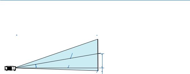
The following shows the proper relative positions of the projector and screen. Refer to the table to determine the position of installation.
Distance Chart [NP610/NP510/NP410/NP405/NP310/NP305/NP510W/NP410W]
|
|
|
|
|
|
|
|
|
|
C |
|
|
|
|
|
|
|
|
|
|
B = |
Vertical distance between lens center and |
||||||||||
|
|
|
|
|
|
|
|
|
|
|
|
|
|
|
|
|
|
|
|
|||||||||||||
|
|
|
|
|
|
|
|
|
|
|
|
|
|
|
|
|
|
|
|
|
|
|
screen center |
|
|
|
|
|
|
|||
|
|
|
|
|
|
|
|
|
|
|
|
|
|
|
|
|
|
|
|
|
|
|
|
|
|
|
|
|
||||
|
|
|
|
|
|
|
|
|
|
|
|
|
|
|
|
|
|
|
|
|
C = |
Throw distance |
|
|
|
|
|
|||||
|
|
|
|
|
|
|
|
|
|
|
|
|
|
|
|
|
|
|
|
|
D = |
Vertical distance between lens center and |
||||||||||
|
|
|
|
|
|
|
|
|
|
|
Screen center |
|
|
|
|
|
|
|
|
|
screen bottom (top of screen for ceiling ap- |
|||||||||||
|
|
|
|
|
|
|
|
|
|
|
|
|
|
|
|
|
|
|
|
|
α = |
plication) |
|
|
|
|
|
|
||||
|
|
|
|
|
|
|
|
|
|
|
Lens center |
|
|
|
|
|
|
B |
Throw angle |
|
|
|
|
|
|
|||||||
|
|
|
|
|
|
|
|
α |
|
|
|
|
|
|
|
|
|
|
|
|
|
|
|
|
|
|
|
|
|
|
||
|
|
|
|
|
|
|
|
|
|
|
|
|
|
|
|
|
|
|
|
|
|
|
|
|
|
|
|
|
|
|
|
|
|
|
|
|
|
|
|
|
|
|
|
|
|
|
|
|
|
|
|
D |
|
|
NOTE: The values in the tables are design values and |
||||||||||
|
|
|
|
|
|
|
|
|
|
|
|
|
|
|
|
|
|
|
|
|||||||||||||
|
|
|
|
|
|
|
|
|
|
|
|
|
|
Screen bottom |
may vary. |
|
|
|
|
|
|
|
|
|
||||||||
[NP610/NP510/NP410/NP405/NP310/NP305] |
|
|
|
|
|
|
|
|
|
|||||||||||||||||||||||
|
|
|
|
|
|
|
|
|
|
|
|
|
|
|
|
|
|
|
||||||||||||||
|
|
|
|
|
|
|
|
|
|
|
|
|
|
|
|
|
|
|
|
|
|
|
|
|
|
|
|
|
|
|
|
|
|
|
|
|
|
|
Screen Size |
|
|
B |
|
|
|
|
|
|
|
|
|
C |
|
|
|
|
|
D |
|
α |
|
||||
|
Diagonal |
Width |
Height |
|
|
|
wide |
|
|
|
tele |
|
|
wide |
|
tele |
||||||||||||||||
|
|
|
|
|
|
|
|
|
|
|
|
|
|
|||||||||||||||||||
|
inch |
|
mm |
inch |
|
mm |
inch |
mm |
inch |
|
mm |
inch |
|
|
|
mm |
- |
inch |
|
mm |
|
inch |
|
mm |
degree |
- |
degree |
|||||
|
21 |
|
533 |
17 |
|
427 |
13 |
320 |
4 |
|
110 |
- |
|
|
- |
|
- |
30 |
|
753 |
|
-2 |
|
-50 |
- |
- |
8.3 |
|||||
|
25 |
|
635 |
20 |
|
508 |
15 |
381 |
5 |
|
131 |
29 |
|
746 |
|
- |
36 |
|
903 |
|
-2 |
|
-60 |
10.0 |
- |
8.3 |
||||||
|
30 |
|
762 |
24 |
|
610 |
18 |
457 |
6 |
|
157 |
36 |
|
903 |
|
- |
43 |
|
1092 |
|
-3 |
|
-71 |
9.9 |
- |
8.2 |
||||||
|
40 |
|
1016 |
32 |
|
813 |
24 |
610 |
8 |
|
210 |
48 |
|
1217 |
|
- |
58 |
|
1469 |
|
-4 |
|
-95 |
9.8 |
- |
8.1 |
||||||
|
60 |
|
1524 |
48 |
|
1219 |
36 |
914 |
12 |
|
314 |
73 |
|
1845 |
|
- |
88 |
|
2223 |
|
-6 |
|
-143 |
9.7 |
- |
8.0 |
||||||
|
72 |
|
1829 |
58 |
|
1463 |
43 |
1097 |
15 |
|
377 |
87 |
|
2221 |
|
- |
105 |
|
2675 |
|
-7 |
|
-171 |
9.6 |
- |
8.0 |
||||||
|
80 |
|
2032 |
64 |
|
1626 |
48 |
1219 |
17 |
|
419 |
97 |
|
2473 |
|
- |
117 |
|
2977 |
|
-8 |
|
-191 |
9.6 |
- |
8.0 |
||||||
|
84 |
|
2134 |
67 |
|
1707 |
50 |
1280 |
17 |
|
440 |
102 |
|
2598 |
|
- |
123 |
|
3128 |
|
-8 |
|
-200 |
9.6 |
- |
8.0 |
||||||
|
90 |
|
2286 |
72 |
|
1829 |
54 |
1372 |
19 |
|
471 |
110 |
|
2787 |
|
- |
132 |
|
3354 |
|
-8 |
|
-214 |
9.6 |
- |
8.0 |
||||||
|
100 |
|
2540 |
80 |
|
2032 |
60 |
1524 |
21 |
|
524 |
122 |
|
3101 |
|
- |
147 |
|
3731 |
|
-9 |
|
-238 |
9.6 |
- |
8.0 |
||||||
|
120 |
|
3048 |
96 |
|
2438 |
72 |
1829 |
25 |
|
629 |
147 |
|
3729 |
|
- |
177 |
|
4485 |
|
-11 |
|
-286 |
9.6 |
- |
8.0 |
||||||
|
150 |
|
3810 |
120 |
|
3048 |
90 |
2286 |
31 |
|
786 |
184 |
|
4671 |
|
- |
221 |
|
5616 |
|
-14 |
|
-357 |
9.5 |
- |
8.0 |
||||||
|
180 |
|
4572 |
144 |
|
3658 |
108 |
2743 |
37 |
|
943 |
221 |
|
5613 |
|
- |
266 |
|
6747 |
|
-17 |
|
-429 |
9.5 |
- |
8.0 |
||||||
|
200 |
|
5080 |
160 |
|
4064 |
120 |
3048 |
41 |
|
1048 |
246 |
|
6241 |
|
- |
295 |
|
7501 |
|
-19 |
|
-476 |
9.5 |
- |
8.0 |
||||||
|
210 |
|
5334 |
168 |
|
4267 |
126 |
3200 |
43 |
|
1100 |
258 |
|
6555 |
|
- |
310 |
|
7878 |
|
-20 |
|
-500 |
9.5 |
- |
7.9 |
||||||
|
240 |
|
6096 |
192 |
|
4877 |
144 |
3658 |
50 |
|
1257 |
295 |
|
7497 |
|
- |
355 |
|
9009 |
|
-23 |
|
-572 |
9.5 |
- |
7.9 |
||||||
|
270 |
|
6858 |
216 |
|
5486 |
162 |
4115 |
56 |
|
1414 |
332 |
|
8439 |
|
- |
399 |
|
10140 |
|
-25 |
|
-643 |
9.5 |
- |
7.9 |
||||||
|
300 |
|
7620 |
240 |
|
6096 |
180 |
4572 |
62 |
|
1572 |
369 |
|
9381 |
|
- |
444 |
|
11271 |
|
-28 |
|
-714 |
9.5 |
- |
7.9 |
||||||
[NP510W/NP410W] |
|
|
|
|
|
|
|
|
|
|
|
|
|
|
|
|
|
|
|
|
|
|
|
|
|
|||||||
|
|
|
|
|
|
|
|
|
|
|
|
|
|
|
|
|
|
|
|
|
|
|
|
|
|
|
|
|
|
|
||
|
|
|
|
|
|
Screen Size |
|
|
B |
|
|
|
|
|
|
|
|
|
C |
|
|
|
|
|
D |
|
α |
|
||||
|
Diagonal |
Width |
Height |
|
|
|
wide |
|
|
|
tele |
|
|
wide |
|
tele |
||||||||||||||||
|
|
|
|
|
|
|
|
|
|
|
|
|
|
|||||||||||||||||||
|
inch |
|
mm |
inch |
|
mm |
inch |
mm |
inch |
|
mm |
inch |
|
|
|
mm |
- |
inch |
|
mm |
|
inch |
|
mm |
degree |
- |
degree |
|||||
|
21 |
|
533 |
18 |
|
452 |
11 |
283 |
5 |
|
117 |
- |
|
|
- |
|
- |
31 |
|
798 |
|
-1 |
|
-25 |
- |
- |
8.3 |
|||||
|
25 |
|
635 |
21 |
|
538 |
13 |
337 |
5 |
|
139 |
31 |
|
791 |
|
- |
38 |
|
957 |
|
-1 |
|
-29 |
10.0 |
- |
8.3 |
||||||
|
30 |
|
762 |
25 |
|
646 |
16 |
404 |
7 |
|
167 |
38 |
|
957 |
|
- |
46 |
|
1158 |
|
-1 |
|
-35 |
9.9 |
- |
8.2 |
||||||
|
40 |
|
1016 |
34 |
|
862 |
21 |
538 |
9 |
|
222 |
51 |
|
1290 |
|
- |
61 |
|
1557 |
|
-2 |
|
-47 |
9.8 |
- |
8.1 |
||||||
|
60 |
|
1524 |
51 |
|
1292 |
32 |
808 |
13 |
|
333 |
77 |
|
1956 |
|
- |
93 |
|
2356 |
|
-3 |
|
-71 |
9.7 |
- |
8.0 |
||||||
|
72 |
|
1829 |
61 |
|
1551 |
38 |
969 |
16 |
|
400 |
93 |
|
2354 |
|
- |
112 |
|
2835 |
|
-3 |
|
-85 |
9.6 |
- |
8.0 |
||||||
|
80 |
|
2032 |
68 |
|
1723 |
42 |
1077 |
17 |
|
444 |
103 |
|
2621 |
|
- |
124 |
|
3156 |
|
-4 |
|
-94 |
9.6 |
- |
8.0 |
||||||
|
84 |
|
2134 |
71 |
|
1809 |
45 |
1131 |
18 |
|
466 |
108 |
|
2754 |
|
- |
131 |
|
3316 |
|
-4 |
|
-99 |
9.6 |
- |
8.0 |
||||||
|
90 |
|
2286 |
76 |
|
1939 |
48 |
1212 |
20 |
|
500 |
116 |
|
2954 |
|
- |
140 |
|
3555 |
|
-4 |
|
-106 |
9.6 |
- |
8.0 |
||||||
|
100 |
|
2540 |
85 |
|
2154 |
53 |
1346 |
22 |
|
555 |
129 |
|
3287 |
|
- |
156 |
|
3955 |
|
-5 |
|
-118 |
9.6 |
- |
8.0 |
||||||
|
120 |
|
3048 |
102 |
|
2585 |
64 |
1615 |
26 |
|
666 |
156 |
|
3953 |
|
- |
187 |
|
4754 |
|
-6 |
|
-141 |
9.6 |
- |
8.0 |
||||||
|
150 |
|
3810 |
127 |
|
3231 |
79 |
2019 |
33 |
|
833 |
195 |
|
4951 |
|
- |
234 |
|
5953 |
|
-7 |
|
-177 |
9.5 |
- |
8.0 |
||||||
|
180 |
|
4572 |
153 |
|
3877 |
95 |
2423 |
39 |
|
1000 |
234 |
|
5950 |
|
- |
282 |
|
7152 |
|
-8 |
|
-212 |
9.5 |
- |
8.0 |
||||||
|
200 |
|
5080 |
170 |
|
4308 |
106 |
2692 |
44 |
|
1111 |
260 |
|
6615 |
|
- |
313 |
|
7951 |
|
-9 |
|
-236 |
9.5 |
- |
8.0 |
||||||
|
210 |
|
5334 |
178 |
|
4523 |
111 |
2827 |
46 |
|
1166 |
274 |
|
6948 |
|
- |
329 |
|
8351 |
|
-10 |
|
-247 |
9.5 |
- |
7.9 |
||||||
|
240 |
|
6096 |
204 |
|
5169 |
127 |
3231 |
52 |
|
1333 |
313 |
|
7947 |
|
- |
376 |
|
9550 |
|
-11 |
|
-283 |
9.5 |
- |
7.9 |
||||||
|
270 |
|
6858 |
229 |
|
5816 |
143 |
3635 |
59 |
|
1499 |
352 |
|
8945 |
|
- |
423 |
|
10748 |
|
-13 |
|
-318 |
9.5 |
- |
7.9 |
||||||
|
300 |
|
7620 |
254 |
|
6462 |
159 |
4039 |
66 |
|
1666 |
391 |
|
9944 |
|
- |
470 |
|
11947 |
|
-14 |
|
-353 |
9.5 |
- |
7.9 |
||||||
15
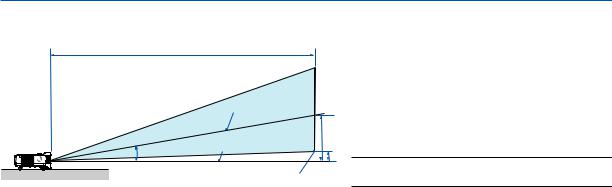
2. Installation and Connections
Distance Chart [NP610S/NP510WS]
C
Screen center
|
B |
|
α |
Lens center |
|
D |
||
|
||
|
Screen bottom |
B = Vertical distance between lens center and screen center
C = Throw distance
D = Vertical distance between lens center and screen bottom (top of screen for ceiling application)
α = Throw angle
NOTE: The values in the tables are design values and may vary.
[NP610S]
|
|
Screen Size |
|
|
|
B |
|
C |
|
D |
α |
||||
Diagonal |
Width |
Height |
|
|
wide |
|
wide |
||||||||
|
|
|
|
|
|
|
|||||||||
inch |
mm |
inch |
mm |
inch |
mm |
inch |
|
mm |
inch |
|
mm |
inch |
|
mm |
degree |
60 |
1524 |
48 |
1219 |
36 |
914 |
20 |
|
505 |
35 |
|
895 |
2 |
|
48 |
29.4 |
64 |
1626 |
51 |
1300 |
38 |
975 |
21 |
|
538 |
38 |
|
956 |
2 |
|
51 |
29.4 |
70 |
1778 |
56 |
1422 |
42 |
1067 |
23 |
|
589 |
41 |
|
1049 |
2 |
|
56 |
29.3 |
77 |
1956 |
62 |
1565 |
46 |
1173 |
26 |
|
648 |
46 |
|
1156 |
2 |
|
61 |
29.3 |
80 |
2032 |
64 |
1626 |
48 |
1219 |
27 |
|
673 |
47 |
|
1203 |
3 |
|
64 |
29.2 |
90 |
2286 |
72 |
1829 |
54 |
1372 |
30 |
|
757 |
53 |
|
1357 |
3 |
|
71 |
29.2 |
100 |
2540 |
80 |
2032 |
60 |
1524 |
33 |
|
841 |
59 |
|
1511 |
3 |
|
79 |
29.1 |
110 |
2794 |
88 |
2235 |
66 |
1676 |
36 |
|
926 |
66 |
|
1665 |
3 |
|
87 |
29.1 |
[NP510WS]
|
|
Screen Size |
|
|
|
B |
|
C |
|
D |
α |
||||
Diagonal |
Width |
Height |
|
|
wide |
|
wide |
||||||||
|
|
|
|
|
|
|
|||||||||
inch |
mm |
inch |
mm |
inch |
mm |
inch |
|
mm |
inch |
|
mm |
inch |
|
mm |
degree |
57 |
1448 |
48 |
1228 |
30 |
767 |
20 |
|
508 |
36 |
|
902 |
5 |
|
125 |
29.4 |
60 |
1524 |
51 |
1292 |
32 |
808 |
21 |
|
535 |
37 |
|
951 |
5 |
|
131 |
29.4 |
70 |
1778 |
59 |
1508 |
37 |
942 |
25 |
|
624 |
44 |
|
1114 |
6 |
|
153 |
29.3 |
80 |
2032 |
68 |
1723 |
42 |
1077 |
28 |
|
713 |
50 |
|
1277 |
7 |
|
175 |
29.2 |
87 |
2210 |
74 |
1874 |
46 |
1171 |
31 |
|
776 |
55 |
|
1392 |
7 |
|
190 |
29.1 |
90 |
2286 |
76 |
1939 |
48 |
1212 |
32 |
|
803 |
57 |
|
1441 |
8 |
|
197 |
29.1 |
94 |
2388 |
80 |
2025 |
50 |
1265 |
33 |
|
838 |
59 |
|
1506 |
8 |
|
206 |
29.1 |
104 |
2642 |
88 |
2240 |
55 |
1400 |
37 |
|
928 |
66 |
|
1669 |
9 |
|
228 |
29.1 |
WARNING
*Installing your projector on the ceiling must be done by a qualified technician.Contact your NEC dealer for more information.
*Do not attempt to install the projector yourself.
•Only use your projector on a solid, level surface.If the projector falls to the ground, you can be injured and the projector severely damaged.
•Do not use the projector where temperatures vary greatly. The projector must be used at temperatures between 41°F (5°C) and 104°F (40°C) (Eco mode selected automatically at 95°F to 104°F/35°C to 40°C).
•Do not expose the projector to moisture, dust, or smoke.This will harm the screen image.
•Ensure that you have adequate ventilation around your projector so heat can dissipate.Do not cover the vents on the side or the front of the projector.
Reflecting the Image
Using a mirror to reflect your projector’s image enables you to enjoy a much larger image when a smaller space is required.Contact your NEC dealer if you need a mirror system. If you’re using a mirror system and your image is inverted, use the MENU and buttons on your projector cabinet or your remote control to correct the orientation. (→ page 72)
16
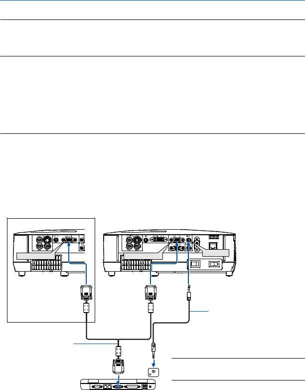
2. Installation and Connections
Making Connections
NOTE: When using with a notebook PC, be sure to connect the projector and notebook PC while the projector is in standby mode and before turning on the power to the notebook PC.
In most cases the output signal from the notebook PC is not turned on unless connected to the projector before being powered up.
*If the screen goes blank while using your remote control, it may be the result of the computer’s screen-saver or power management software.
Enabling the computer’s external display
Displaying an image on the notebook PC’s screen does not necessarily mean it outputs a signal to the projector. When using a PC compatible laptop, a combination of function keys will enable/disable the external display. Usually, the combination of the “Fn” key along with one of the 12 function keys gets the external display to come on or off. For example, NEC laptops use Fn + F3, while Dell laptops use Fn + F8 key combinations to toggle through external display selections.
Connecting Your PC or Macintosh Computer
NOTE: Signals supported by Plug & Play (DDC2)
|
|
INPUT |
|
|
|
Model |
COMPUTER 1 IN |
|
COMPUTER 2 IN |
|
|
|
analog |
analog |
|
digital |
|
NP610/NP510/NP410/NP310/ |
Yes |
Yes |
|
Yes |
|
NP510W/NP410W/NP610S/NP510WS |
|
|
|||
|
|
|
|
|
|
NP405/NP305 |
Yes |
Yes |
|
— |
|
|
|
|
|
|
|
NP405/NP305 |
COMPUTER 2 IN |
COMPUTER |
AUDIO IN |
|
Audio cable (not supplied)
VGA signal cable (supplied)
To mini D-Sub 15-pin connector on the projector. It is recommended that you use a commercially available distribution amplifier if connecting a signal cable longer than the cable
supplied. |
PHONE |
|
IBM VGA or Compatibles (Notebook type) or Macintosh (Notebook type)
NOTE: For older Macintosh, use a commercially available pin adapter (not supplied) to connect to your Mac’s video port.
17
2. Installation and Connections
• Select the source name for its appropriate input connector after turning on the projector.
[NP610/NP510/NP410/NP310/NP510W/NP410W/NP610S/NP510WS]
|
Input connector |
SOURCE button on the projector |
Button on the remote control |
|
cabinet |
||
|
|
|
|
|
|
|
|
|
COMPUTER 1 IN |
COMPUTER1 |
(COMPUTER 1) |
|
|
|
|
|
|
COMPUTER 2(DIGITAL) |
|
|
COMPUTER 2(DVI-I)IN |
or |
(COMPUTER 2) |
|
|
COMPUTER 2(ANALOG) |
|
|
|
|
|
[NP405/NP305] |
|
|
|
|
|
|
|
|
Input connector |
SOURCE button on the projector |
Button on the remote control |
|
cabinet |
||
|
|
|
|
|
|
|
|
|
COMPUTER 1 IN |
COMPUTER 1 |
(COMPUTER 1) |
|
|
|
|
|
COMPUTER 2 IN |
COMPUTER 2 |
(COMPUTER 2) |
|
|
|
|
NOTE: The projector is not compatible with video decoded outputs of the NEC ISS-6020 switcher.
NOTE: An image may not be displayed correctly when a Video or S-Video source is played back via a commercially available scan converter.
This is because the projector will process a video signal as a computer signal at the default setting. In that case, do the following.
*When an image is displayed with the lower and upper black portion of the screen or a dark image is not displayed correctly:
Project an image to fill the screen and then press the AUTO ADJ. button on the remote control or the projector cabinet.
18
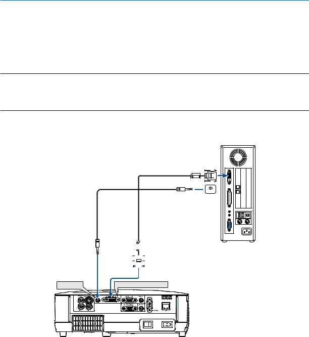
2. Installation and Connections
When Viewing a DVI Digital Signal (except NP405 and NP305)
To project a DVI digital signal, be sure to connect the PC and the projector using a DVI cable (not supplied) before turning on your PC or projector.Turn on the projector first and select Computer 2 (Digital) from the source menu before turning on your PC.
Failure to do so may not activate the digital output of the graphics card resulting in no picture being displayed. Should this happen, restart your PC.
Do not disconnect the DVI cable while the projector is running. If the signal cable has been disconnected and then re-connected, an image may not be correctly displayed. Should this happen, restart your PC.
NOTE:
•Use a DVI cable or the one compliant with the DDWG (Digital Display Working Group) DVI (Digital Visual Interface) revision 1.0 standard. The DVI cable should be within 5 m (196") long. Both single and dual types of DVI cable can be used.
•The DVI (DIGITAL) connector accepts VGA (640 x 480), SVGA (800 x 600), 1152 x 864, XGA (1024 x 768), WXGA (1280 x 800 @ up to 60Hz), and SXGA (1280 x 1024 @ up to 60Hz).
IBM PC or Compatibles (Desktop type) or Macintosh (Desktop type)

 PHONE
PHONE
Audio cable (not supplied) |
|
|
|
|
|
|
|
|
|
DVI cable (not supplied) |
|
|
|
|
|
|
|
|
|||
|
|
|
|
|
|
|
|
|
|
|
|
|
|
|
|
|
|
|
|
|
|
|
|
|
|
|
|
|
|
|
|
|
|
|
|
|
|
|
|
|
|
|
|
|
|
|
|
|
|
|
|
|
|
|
|
|
|
|
|
|
|
|
|
|
|
AUDIO IN |
2 (DVI-I) IN |
19
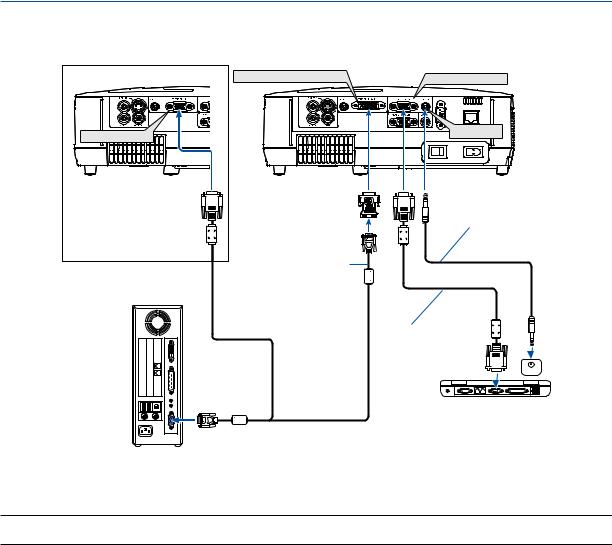
2. Installation and Connections
Using Two Analog COMPUTER Inputs Simultaneously
If you need to use two analog COMPUTER inputs simultaneously, connect a VGA signal cable as shown below.
NP405/NP305 |
COMPUTER 2 IN |
COMPUTER 2 (DVI-I) IN |
COMPUTER 1 IN |


 AUDIO IN
DVI to VGA adapter 
 (supplied)
Audio cable (not supplied)
VGA signal cable (not supplied)
VGA signal cable (supplied)
 PHONE
PHONE
IBM PC or Compatibles (Notebook type) or Macintosh (Notebook type)
IBM PC or Compatibles (Desktop type) or Macintosh (Desktop type)
NOTE: When the DVI to VGA adapter is not to be used for an extended period of time, remove it from the projector. Failure to do so may cause damage to the connector of the projector.
20
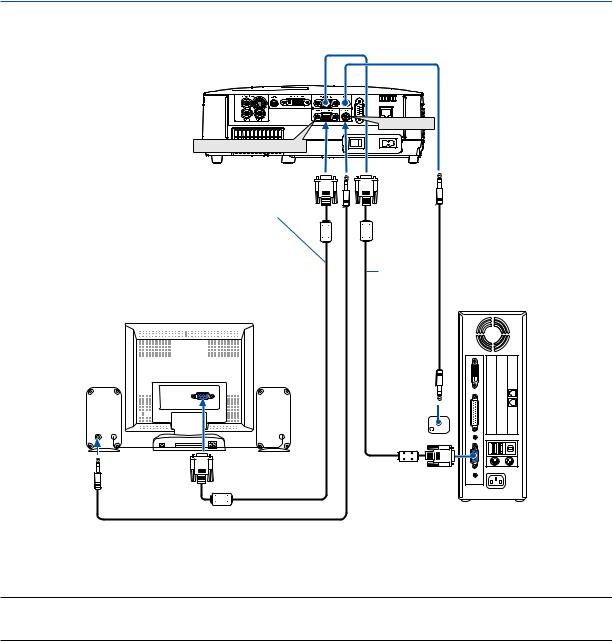
2. Installation and Connections
Connecting an External Monitor
AUDIO OUT
MONITOR OUT (COMP 1)
VGA signal cable (not supplied)
VGA signal cable (supplied)
AUDIO |
|
IN |
PHONE |
You can connect a separate, external monitor to your projector to simultaneously view on a monitor the computer analog image you’re projecting.
NOTE:
•Daisy chain connection is not possible.
•When audio equipment is connected, the projector speaker is disabled.
21
Loading...