


INSTRUCTION MANUAL
MANUEL D'INSTRUCTION
MANUAL DE INSTRUCCIONES
Nibbler
Grignoteuse
Roedora
JN3201
013354
DOUBLE INSULATION
DOUBLE ISOLATION
DOBLE AISLAMIENTO
IMPORTANT: Read Before Using.
IMPORTANT: Lire avant usage.
IMPORTANTE: Leer antes de usar.

ENGLISH (Original instructions)
SPECIFICATIONS
Model |
|
JN3201 |
|
|
|
Mild steel |
3.2 mm / 10 ga |
Max. cutting capacities |
|
Stainless |
2.5 mm / 13 ga |
|
|
Aluminum |
3.5 mm / 10 ga |
Min. cutting radius |
|
Outside edge |
128 mm (5-1/16") |
|
Inside edge |
120 mm (4-3/4") |
|
|
|
||
Strokes per minute |
|
1,300 |
|
Overall length |
|
225 mm (8-7/8") |
|
Net weight |
|
3.4 kg (7.4 lbs) |
|
•Due to our continuing program of research and development, the specifications herein are subject to change without notice.
•Specifications may differ from country to country.
•Weight according to EPTA-Procedure 01/2003
GEA008-2
General Power Tool Safety Warnings
 WARNING Read all safety warnings and all instructions. Failure to follow the warnings and instructions may result in electric shock, fire and/or serious injury.
Save all warnings and instructions for future reference.
The term "power tool" in the warnings refers to your mains-operated (corded) power tool or battery-operated (cordless) power tool.
Work area safety
1.Keep work area clean and well lit. Cluttered or dark areas invite accidents.
2.Do not operate power tools in explosive atmospheres, such as in the presence of flammable liquids, gases or dust. Power tools create sparks which may ignite the dust or fumes.
3.Keep children and bystanders away while
operating a power tool. Distractions can cause you to lose control.
Electrical Safety
4.Power tool plugs must match the outlet. Never modify the plug in any way. Do not use any adapter plugs with earthed (grounded) power tools. Unmodified plugs and matching outlets will reduce risk of electric shock.
5.Avoid body contact with earthed or grounded surfaces such as pipes, radiators, ranges and refrigerators. There is an increased risk of electric shock if your body is earthed or grounded.
6.Do not expose power tools to rain or wet conditions. Water entering a power tool will increase the risk of electric shock.
7.Do not abuse the cord. Never use the cord for carrying, pulling or unplugging the power tool. Keep cord away from heat, oil, sharp edges or moving parts. Damaged or entangled cords increase the risk of electric shock.
8.When operating a power tool outdoors, use an extension cord suitable for outdoor use. Use of a cord suitable for outdoor use reduces the risk of electric shock.
9.If operating a power tool in a damp location is unavoidable, use a ground fault circuit interrupter (GFCI) protected supply. Use of an GFCI reduces the risk of electric shock.
Personal Safety
10.Stay alert, watch what you are doing and use common sense when operating a power tool. Do not use a power tool while you are tired or under the influence of drugs, alcohol or medication. A moment of inattention while operating power tools may result in serious personal injury.
11.Use personal protective equipment. Always wear eye protection. Protective equipment such as dust mask, non-skid safety shoes, hard hat, or hearing protection used for appropriate conditions will reduce personal injuries.
12.Prevent unintentional starting. Ensure the switch is in the off-position before connecting to power source and/or battery pack, picking up or carrying the tool. . Carrying power tools with your finger on the switch or energising power tools that have the switch on invites accidents.
13.Remove any adjusting key or wrench before turning the power tool on. A wrench or a key left attached to a rotating part of the power tool may result in personal injury.
2

14.Do not overreach. Keep proper footing and balance at all times. This enables better control of the power tool in unexpected situations.
15.Dress properly. Do not wear loose clothing or jewellery. Keep your hair, clothing, and gloves away from moving parts. Loose clothes, jewellery or long hair can be caught in moving parts.
16.If devices are provided for the connection of dust extraction and collection facilities, ensure these are connected and properly used. Use of dust collection can reduce dustrelated hazards.
Power tool use and care
17.Do not force the power tool. Use the correct power tool for your application. The correct power tool will do the job better and safer at the rate for which it was designed.
18.Do not use the power tool if the switch does not turn it on and off. Any power tool that cannot be controlled with the switch is dangerous and must be repaired.
19.Disconnect the plug from the power source and/or the battery pack from the power tool before making any adjustments, changing accessories, or storing power tools. Such preventive safety measures reduce the risk of starting the power tool accidentally.
21.Maintain power tools. Check for misalignment or binding of moving parts, breakage of parts and any other condition that may affect the power tool’s operation. If damaged, have the power tool repaired before use. Many accidents are caused by poorly maintained power tools.
22.Keep cutting tools sharp and clean. Properly maintained cutting tools with sharp cutting edges are less likely to bind and are easier to control.
23.Use the power tool, accessories and tool bits etc. in accordance with these instructions, taking into account the working conditions
and the work to be performed. Use of the power tool for operations different from those intended could result in a hazardous situation.
Service
24.Have your power tool serviced by a qualified repair person using only identical replacement parts. This will ensure that the safety of the power tool is maintained.
25.Follow instruction for lubricating and changing accessories.
26.Keep handles dry, clean and free from oil and grease.
USE PROPER EXTENSION CORD. Make sure your extension cord is in good condition. When using an extension cord, be sure to use one heavy enough to
20.Store idle power tools out of the reach of carry the current your product will draw. An undersized children and do not allow persons unfamiliar cord will cause a drop in line voltage resulting in loss of with the power tool or these instructions to power and overheating. Table 1 shows the correct size
operate the power tool. Power tools are |
to use depending on cord length and nameplate ampere |
dangerous in the hands of untrained users. |
rating. If in doubt, use the next heavier gage. The |
|
smaller the gage number, the heavier the cord. |
Table 1: Minimum gage for cord
|
Volts |
|
Total length of cord in feet |
|
|
|
|
|
|
|
|
Ampere Rating |
120V |
25 ft. |
50 ft. |
100 ft. |
150 ft. |
|
220V - 240V |
50 ft. |
100 ft. |
200 ft. |
300 ft. |
More Than |
Not More Than |
|
AWG |
|
|
0 |
6 |
18 |
16 |
16 |
14 |
6 |
10 |
18 |
16 |
14 |
12 |
10 |
12 |
16 |
16 |
14 |
12 |
12 |
16 |
14 |
12 |
Not Recommended |
|
000300 |
|
|
|
|
|
3
GEB028-2
NIBBLER SAFETY WARNINGS
1.Hold the tool firmly.
2.Secure the workpiece firmly.
3.Keep hands away from moving parts.
4.Edges and chips of the workpiece are sharp. Wear gloves. It is also recommended that you put on thickly bottomed shoes to prevent injury.
5.Do not put the tool on the chips of the workpiece. Otherwise it can cause damage and trouble on the tool.
6.Do not leave the tool running. Operate the tool only when hand-held.
7.Always be sure you have a firm footing.
Be sure no one is below when using the tool in high locations.
8.Do not touch the punch, die or the workpiece immediately after operation; they may be extremely hot and could burn your skin.
9.Avoid cutting electrical wires. It can cause serious accident by electric shock.
SAVE THESE INSTRUCTIONS.
 WARNING:
DO NOT let comfort or familiarity with product (gained from repeated use) replace strict adherence to safety rules for the subject product. MISUSE or failure to follow the safety rules stated in this instruction manual may cause serious personal injury.
USD201-2
Symbols
The followings show the symbols used for tool.
volts
amperes
hertz
alternating current
no load speed
Class II Construction
revolutions or reciprocation per minute
FUNCTIONAL DESCRIPTION
 CAUTION:
•Always be sure that the tool is switched off and unplugged before adjusting or checking function on the tool.
Permissible cutting thickness
|
1. |
Stainless steel |
|
|
gauge 2.5 mm |
|
|
(3/32") |
1 |
2. |
Mild steel |
|
gauge 3.2 mm |
|
|
|
|
2 |
|
(1/8") |
|
|
013355
The thickness of material to be cut depends upon the tensile strength of the material itself. The groove on the die holder acts as a thickness gauge for allowable cutting thickness. Do not attempt to cut any material which will not fit into this groove.
Max.cutting capacities |
mm |
ga |
Steel up to 400 N/mm2 |
3.2 |
10 |
Steel up to 600 N/mm2 |
2.5 |
13 |
Steel up to 800 N/mm2 |
1.0 |
20 |
Aluminum up to 200 N/mm2 |
3.5 |
10 |
006439
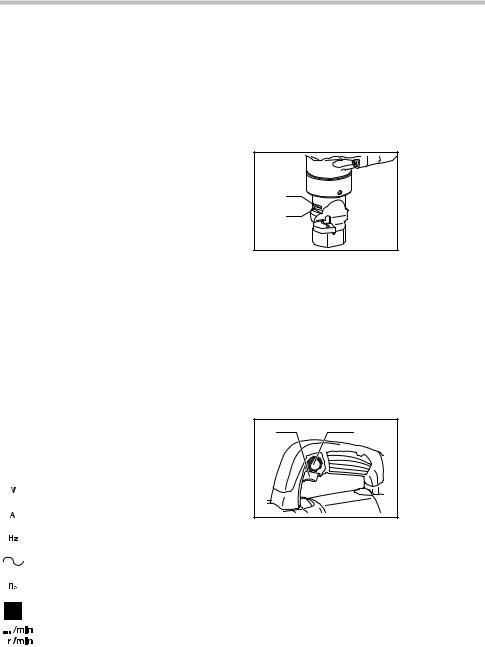
Switch action
1 |
2 |
1. |
Switch trigger |
|
2. |
Lock button |
|||
|
|
013356
 CAUTION:
•Before plugging in the tool, always check to see that the switch trigger actuates properly and returns to the "OFF" position when released.
•Switch can be locked in "ON" position for ease of operator comfort during extended use. Apply caution when locking tool in "ON" position and maintain firm grasp on tool.
To start the tool, simply pull the switch trigger. Release the switch trigger to stop.
For continuous operation, pull the switch trigger and then push in the lock button.
To stop the tool from the locked position, pull the switch trigger fully, then release it.
4

ASSEMBLY
 CAUTION:
•Always be sure that the tool is switched off and unplugged before carrying out any work on the tool.
Punch replacement
1. Wrench
1 2. Lock nut
3. Die holder
2
3
013357
Fit the wrench provided onto the lock nut and tap the handle lightly with a hammer to loosen the lock nut. Take off the die holder and use a wrench to remove the screw. Then remove the punch.
1 |
|
1. Punch |
3 |
2. Screw |
|
2 |
3. Wrench |
|
|
|
|
013358 |
|
|
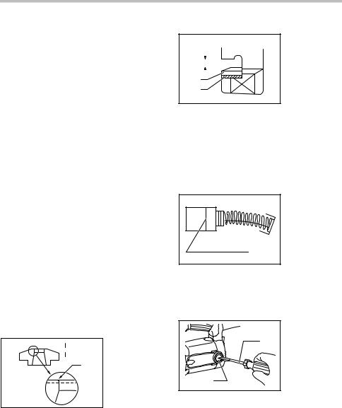
To install the punch, insert it into the punch holder with its cutting edge facing forward so that the pin in the punch holder fits into the groove in the punch. Install the screw and lock nut. Then tighten them securely.
NOTE:
•When installing the screw and lock nut, be sure to tighten securely. If they become loose during operation, the tool may break down.
|
|
1. |
Cutting edge |
|
|
|
2. |
Punch |
|
|
1 |
3. Groove |
||
2 |
4. |
Punch holder |
||
3 |
5. |
Pin |
||
4 |
||||
|
|
|
||
5
004785
OPERATION
 CAUTION:
•Hold the tool firmly with one hand on the main handle when performing the tool.
Pre-lubrication
Coat the cutting line with machine oil to increase the punch and die service life. This is particularly important when cutting aluminum.
Cutting method
013359 |
Smooth cutting is achieved by holding the tool upright and applying gentle pressure in the cutting direction. Apply tool oil to the punch about every 10 meters (32.8 feet) of mild steel or stainless steel to be cut. Light oil or kerosene should be used to keep an aluminum lubricated continuously. Failure to lubricate aluminum in the cut will cause chips to adhere to the tool, dulling the die and punch and increasing load on the motor.
Cutouts |
013360 |
Cutouts can be done by first opening a round hole of about 42 mm (1-5/8") diameter or more in the material.
Cutting stainless steel
|
3 |
1. |
Screw |
|
1 |
2. |
Hex wrench |
||
|
||||
|
3. Washer |
|||
|
|
|||
|
|
4. Insert washer in |
||
|
|
|
between |
|
|
4 |
5. Die |
||
|
|
|
||
2 |
5 |
|
|
|
|
|
|
||
004792
5
There is more vibration when cutting stainless steel than mild steel. Less vibration and better cutting is possible by adding another washer (standard equipment) beneath the die.
Use the hex wrench provided to remove the two screws and insert the washer below the die. Replace screws and tighten securely.
MAINTENANCE
 CAUTION:
•Always be sure that the tool is switched off and unplugged before attempting to perform inspection or maintenance.
•Never use gasoline, benzine, thinner, alcohol or the like. Discoloration, deformation or cracks may result.
The tool and its air vents have to be kept clean. Regularly clean the tool's air vents or whenever the vents start to become obstructed.
Punch & die service life
Replace or sharpen punch and die after cutting the lengths indicated in the accompanying table. Their life, of course, depends upon the thickness of materials cut and lubrication conditions.
Punch |
Replace after 150 m (492 ft.) of 3.2 mm (1/8") steel sheet |
|
|
Die |
Sharpen after 300 m (984 ft.) of 3.2 mm (1/8") steel sheet |
|
|
006440
When cutting is poor even after replacing the punch, sharpen the die. Grind down the dull edge shown in the figure using a grinder. After rough-grinding the dull portion, finish with a dressing stone. Stock removal should be about 0.3 to 0.4 mm (1/64").
1. Grind/sharpen; 


 1 0.3 - 0.4 mm
(1/64")
2 2. Remove dull portion
004793
When installing ground die, a clearance of 3.5 to 4.0 mm (1/8" to 5/32") should be obtained by attaching one or two of the washer provided, as shown in the figure. Failure to have the proper clearance will result in vibration during cutting.
|
1. |
3.5 -4.0 mm |
||||
|
|
|
|
|
|
(1/8" - 5/32") |
|
|
|
2. |
Die |
||
|
|
|||||
1 |
|
|
|
|
3. Washer |
|
|
|
|
|
|||
|
|
|
|
|
|
|
|
|
|
|
|
|
|
2
3
004794
 CAUTION:
•Secure installing screws carefully when installing. A loose screw can cause tool breakage during operation.
NOTE:
•The die can be sharpened two times. After two sharpenings, it should be replaced with new one.
Replacing carbon brushes
1. Limit mark
1
001145
Remove and check the carbon brushes regularly. Replace when they wear down to the limit mark. Keep the carbon brushes clean and free to slip in the holders. Both carbon brushes should be replaced at the same time. Use only identical carbon brushes.
|
1. |
Screwdriver |
|
2. |
Brush holder |
1 |
|
cap |
2 |
|
|
013361 |
|
|
Use a screwdriver to remove the brush holder caps. Take out the worn carbon brushes, insert the new ones and secure the brush holder caps.
To maintain product SAFETY and RELIABILITY, repairs, any other maintenance or adjustment should be performed by Makita Authorized or Factory Service Centers, always using Makita replacement parts.
6

OPTIONAL ACCESSORIES
 CAUTION:
•These accessories or attachments are
recommended for use with your Makita tool specified in this manual. The use of any other accessories or attachments might present a risk of injury to persons. Only use accessory or attachment for its stated purpose.
If you need any assistance for more details regarding these accessories, ask your local Makita Service Center.
•Die
•Punch
•Hex wrench
•Wrench 50
•Die height adjustment washer
NOTE:
•Some items in the list may be included in the tool package as standard accessories. They may differ from country to country.
MAKITA LIMITED ONE YEAR WARRANTY
Warranty Policy
Every Makita tool is thoroughly inspected and tested before leaving the factory. It is warranted to be free of defects from workmanship and materials for the period of ONE YEAR from the date of original purchase. Should any trouble develop during this one year period, return the COMPLETE tool, freight prepaid, to one of Makita’s Factory or Authorized Service Centers. If inspection shows the trouble is caused by defective workmanship or material, Makita will repair (or at our option, replace) without charge.
This Warranty does not apply where:
repairs have been made or attempted by others:
repairs are required because of normal wear and tear:
the tool has been abused, misused or improperly maintained:
alterations have been made to the tool.
IN NO EVENT SHALL MAKITA BE LIABLE FOR ANY INDIRECT, INCIDENTAL OR CONSEQUENTIAL DAMAGES FROM THE SALE OR USE OF THE PRODUCT. THIS DISCLAIMER APPLIES BOTH DURING AND AFTER THE TERM OF THIS WARRANTY.
MAKITA DISCLAIMS LIABILITY FOR ANY IMPLIED WARRANTIES, INCLUDING IMPLIED WARRANTIES OF "MERCHANTABILITY" AND "FITNESS FOR A SPECIFIC PURPOSE," AFTER THE ONE YEAR TERM OF THIS WARRANTY.
This Warranty gives you specific legal rights, and you may also have other rights which vary from state to state. Some states do not allow the exclusion or limitation of incidental or consequential damages, so the above limitation or exclusion may not apply to you. Some states do not allow limitation on how long an implied warranty lasts, so the above limitation may not apply to you.
EN0006-1
7

FRANÇAIS (Mode d’emploi original)
SPÉCIFICATIONS
Modèle |
|
JN3201 |
|
|
|
Acier doux |
3,2 mm / 10 ga |
Capacités de coupe max. |
|
Acier inoxydable |
2,5 mm / 13 ga |
|
|
Aluminium |
3,5 mm / 10 ga |
Rayon de coupe min. |
|
Bord extérieur |
128 mm (5-1/16") |
|
Bord intérieur |
120 mm (4-3/4") |
|
|
|
||
Nombre d'impacts par minute |
1 300 |
||
Longueur totale |
|
225 mm (8-7/8") |
|
Poids net |
|
3,4 kg (7,4 lbs) |
|
•Étant donné l'évolution constante de notre programme de recherche et de développement, les spécifications contenues dans ce manuel sont sujettes à modification sans préavis.
•Les spécifications peuvent varier suivant les pays.
• Poids conforme à la procédure EPTA du 01/2003
GEA008-2
Consignes de sécurité générales pour outils électriques
 MISE EN GARDE Veuillez lire toutes les mises en garde de sécurité et toutes les instructions.
L'ignorance des mises en garde et des instructions comporte un risque de choc électrique, d'incendie et/ou de blessure grave.
Conservez toutes les mises en garde et instructions pour référence future.
Le terme outil électrique qui figure dans les avertissements fait référence à un outil électrique branché sur une prise de courant (par un cordon d'alimentation) ou alimenté par batterie (sans fil).
Sécurité de la zone de travail
1.Maintenez la zone de travail propre et bien éclairée. Les zones de travail encombrées ou sombres ouvrent grande la porte aux accidents.
2.N'utilisez pas les outils électriques dans les atmosphères explosives, par exemple en présence de liquides, gaz ou poussières inflammables. Les outils électriques produisent des étincelles au contact desquelles la poussière ou les vapeurs peuvent s'enflammer.
3.Assurez-vous qu'aucun enfant ou curieux ne s'approche pendant que vous utilisez un outil électrique. Vous risquez de perdre la maîtrise de l'outil si votre attention est détournée.
Sécurité en matière d'électricité
4.Les fiches d'outil électrique sont conçues pour s'adapter parfaitement aux prises de courant. Ne modifiez jamais la fiche de quelque façon que ce soit. N'utilisez aucun adaptateur de fiche sur les outils électriques avec mise à la terre. En ne modifiant pas les fiches et en les insérant dans des prises de courant pour lesquelles elles ont été conçues vous réduirez les risques de choc électrique.
5.Évitez tout contact corporel avec les surfaces mises à la terre, telles que les tuyaux, radiateurs, cuisinières et réfrigérateurs. Le risque de choc électrique est plus élevé si votre corps se trouve mis à la terre.
6.N'exposez pas les outils électriques à la pluie ou à l'eau. La présence d'eau dans un outil électrique augmente le risque de choc électrique.
7.Ne maltraitez pas le cordon. N'utilisez jamais le cordon pour transporter, tirer ou débrancher l'outil électrique. Maintenez le cordon à l'écart des sources de chaleur, de l'huile, des objets à bords tranchants et des pièces en mouvement. Le risque de choc électrique est plus élevé lorsque les cordons sont endommagés ou enchevêtrés.
8.Lorsque vous utilisez un outil électrique à l'extérieur, utilisez un cordon prolongateur prévu à cette fin. Les risques de choc électrique sont moindres lorsqu'un cordon conçu pour l'extérieur est utilisé.
9.Si vous devez utiliser un outil électrique dans un endroit humide, utilisez une source d'alimentation protégée par un disjoncteur de fuite à la terre. L'utilisation d'un disjoncteur de fuite à la terre réduit le risque de choc électrique.
8
 Loading...