


 Loading...
Software Manual
L-force Loader
L
This Manual is valid for the »L-force Loader« as of version 4.0 DMS 4.0 EN - 07/2007 - TD05/TD19
Copyright
© 2007 Lenze Drive Systems GmbH. All rights reserved.
Imprint
Lenze Drive Systems GmbH
Postfach 10 13 52, D-31763 Hameln, Germany
Phone: ++49 (0)5154 / 82-0
Fax: ++49 (0)5154 / 82-2111
E-Mail: Lenze@Lenze.de
Copyright information
All texts, photos and graphics contained in this documentation are subject to copyright protection. No part of this documentation may be copied or made available to third parties without the explicit written approval of Lenze Drive Systems GmbH.
Liability
All information given in this documentation has been selected carefully and tested for compliance with the described hardware and software. Nevertheless, discrepancies cannot be ruled out. We do not accept any responsibility or liability for any damage that may occur. Required corrections will be included in updates of this documentation.
Trademarks
Microsoft and Windows are either registered trademarks or trademarks of Microsoft Corporation in the U.S.A and/or other countries.
Adobe and Reader are either registered trademarks or trademarks of Adobe Systems Incorporated in the U.S.A.and/or other countries.
All other product names contained in this documentation are trademarks of the corresponding owners.
2 |
DMS 4.0 EN - 07/2007 - TD05/TD19 |
L

L-force Loader
Contents
Contents
1 |
About this Manual . . . . . . . . . . . . . . . . . . . . . . . . . . . . . . . . . . . . . . . . . . . . . . . . . . . . . . . . . . . . . . . . |
5 |
|
|
1.1 |
Conventions used . . . . . . . . . . . . . . . . . . . . . . . . . . . . . . . . . . . . . . . . . . . . . . . . . . . . . . . . . . . . . . . |
5 |
|
1.2 |
Layout of the safety instructions . . . . . . . . . . . . . . . . . . . . . . . . . . . . . . . . . . . . . . . . . . . . . . . . . |
6 |
2 |
System requirements . . . . . . . . . . . . . . . . . . . . . . . . . . . . . . . . . . . . . . . . . . . . . . . . . . . . . . . . . . . . . . |
7 |
|
|
2.1 |
Supported target systems . . . . . . . . . . . . . . . . . . . . . . . . . . . . . . . . . . . . . . . . . . . . . . . . . . . . . . . |
7 |
|
2.2 |
Connection with the target system. . . . . . . . . . . . . . . . . . . . . . . . . . . . . . . . . . . . . . . . . . . . . . . |
8 |
3 |
Software installation . . . . . . . . . . . . . . . . . . . . . . . . . . . . . . . . . . . . . . . . . . . . . . . . . . . . . . . . . . . . . . |
9 |
|
4 |
User interface . . . . . . . . . . . . . . . . . . . . . . . . . . . . . . . . . . . . . . . . . . . . . . . . . . . . . . . . . . . . . . . . . . . . |
10 |
|
|
4.1 |
Language selection. . . . . . . . . . . . . . . . . . . . . . . . . . . . . . . . . . . . . . . . . . . . . . . . . . . . . . . . . . . . . . |
10 |
|
4.2 |
Menu bar . . . . . . . . . . . . . . . . . . . . . . . . . . . . . . . . . . . . . . . . . . . . . . . . . . . . . . . . . . . . . . . . . . . . . . . |
11 |
|
4.3 |
Toolbar . . . . . . . . . . . . . . . . . . . . . . . . . . . . . . . . . . . . . . . . . . . . . . . . . . . . . . . . . . . . . . . . . . . . . . . . . |
13 |
|
4.4 |
Function area . . . . . . . . . . . . . . . . . . . . . . . . . . . . . . . . . . . . . . . . . . . . . . . . . . . . . . . . . . . . . . . . . . . |
13 |
|
4.5 |
Dialog area . . . . . . . . . . . . . . . . . . . . . . . . . . . . . . . . . . . . . . . . . . . . . . . . . . . . . . . . . . . . . . . . . . . . . |
13 |
|
4.6 |
Status bar . . . . . . . . . . . . . . . . . . . . . . . . . . . . . . . . . . . . . . . . . . . . . . . . . . . . . . . . . . . . . . . . . . . . . . |
13 |
5 |
Operation . . . . . . . . . . . . . . . . . . . . . . . . . . . . . . . . . . . . . . . . . . . . . . . . . . . . . . . . . . . . . . . . . . . . . . . . |
14 |
|
|
5.1 |
How to configure the communication settings. . . . . . . . . . . . . . . . . . . . . . . . . . . . . . . . . . . . |
14 |
|
|
5.1.1 Example: Configuring a point-to-point connection via LECOM. . . . . . . . . . . . . . |
16 |
|
5.2 |
How to select a target system. . . . . . . . . . . . . . . . . . . . . . . . . . . . . . . . . . . . . . . . . . . . . . . . . . . . |
18 |
|
5.3 |
How to build up a connection with the target system . . . . . . . . . . . . . . . . . . . . . . . . . . . . . |
19 |
|
5.4 |
How to select files for the download . . . . . . . . . . . . . . . . . . . . . . . . . . . . . . . . . . . . . . . . . . . . . |
20 |
|
|
5.4.1 How to open a DDS binary file . . . . . . . . . . . . . . . . . . . . . . . . . . . . . . . . . . . . . . . . . . . . |
21 |
|
|
5.4.2 How to open application data . . . . . . . . . . . . . . . . . . . . . . . . . . . . . . . . . . . . . . . . . . . . |
22 |
|
|
5.4.3 How to open a GDC parameter set file . . . . . . . . . . . . . . . . . . . . . . . . . . . . . . . . . . . . |
23 |
|
|
5.4.4 How to open a 9400 application . . . . . . . . . . . . . . . . . . . . . . . . . . . . . . . . . . . . . . . . . . |
24 |
|
5.5 |
How to download data . . . . . . . . . . . . . . . . . . . . . . . . . . . . . . . . . . . . . . . . . . . . . . . . . . . . . . . . . . |
25 |
|
|
5.5.1 Parameter set transfer . . . . . . . . . . . . . . . . . . . . . . . . . . . . . . . . . . . . . . . . . . . . . . . . . . . |
27 |
|
5.6 |
How to end the connection with the target system . . . . . . . . . . . . . . . . . . . . . . . . . . . . . . . |
28 |
|
5.7 |
How to exit the L-force Loader . . . . . . . . . . . . . . . . . . . . . . . . . . . . . . . . . . . . . . . . . . . . . . . . . . . |
28 |
6 |
Control via script files . . . . . . . . . . . . . . . . . . . . . . . . . . . . . . . . . . . . . . . . . . . . . . . . . . . . . . . . . . . . . |
29 |
|
|
6.1 |
Structure of the script file. . . . . . . . . . . . . . . . . . . . . . . . . . . . . . . . . . . . . . . . . . . . . . . . . . . . . . . . |
29 |
|
6.2 |
Example of a script file . . . . . . . . . . . . . . . . . . . . . . . . . . . . . . . . . . . . . . . . . . . . . . . . . . . . . . . . . . |
33 |
|
6.3 |
Syntax of the command line call . . . . . . . . . . . . . . . . . . . . . . . . . . . . . . . . . . . . . . . . . . . . . . . . . |
34 |
|
6.4 |
Batch mode commands . . . . . . . . . . . . . . . . . . . . . . . . . . . . . . . . . . . . . . . . . . . . . . . . . . . . . . . . . |
35 |
L
DMS 4.0 EN - 07/2007 |
3 |

L-force Loader
Contents
7 |
Appendix . . . . . . . . . . . . . . . . . . . . . . . . . . . . . . . . . . . . . . . . . . . . . . . . . . . . . . . . . . . . . . . . . . . . . . . . |
36 |
|
|
7.1 |
Error numbers, causes & remedies . . . . . . . . . . . . . . . . . . . . . . . . . . . . . . . . . . . . . . . . . . . . . . . |
36 |
|
7.2 |
Log files . . . . . . . . . . . . . . . . . . . . . . . . . . . . . . . . . . . . . . . . . . . . . . . . . . . . . . . . . . . . . . . . . . . . . . . . |
40 |
|
7.3 |
File header for application data . . . . . . . . . . . . . . . . . . . . . . . . . . . . . . . . . . . . . . . . . . . . . . . . . . |
43 |
8 |
Index |
. . . . . . . . . . . . . . . . . . . . . . . . . . . . . . . . . . . . . . . . . . . . . . . . . . . . . . . . . . . . . . . . . . . . . . . . . . . . |
44 |
|
Your opinion is important to us. . . . . . . . . . . . . . . . . . . . . . . . . . . . . . . . . . . . . . . . . . . . . . . . . . . . . . . . . |
45 |
|
4 |
DMS 4.0 EN - 07/2007 |
L

L-force Loader
About this Manual
Conventions used
1 |
About this Manual |
This Manual contains information about the »L-force Loader«.
The »L-force Loader« is a software to transfer PLC programs, parameter sets and application data from a PC to Lenze target systems.
Special features of the »L-force Loader«:
rIntuitive program operation via an easy-to-use PC user interface.
rProgram control by means of script files for automated downloads to several target systems without the necessity of additional user inputs.
rDownload of DDS binary files, application data (e.g. *.lc9 files created with Cam Designer or *.lc7 files created with GDC) and GDC parameter set files via the system bus (CAN) or LECOM.
rDownload of L-force 9400 applications created with the Engineer via the system bus (CAN), Ethernet NRT or diagnostic adapter.
rRecording of all important events.
1.1Conventions used
This Manual uses the following conventions to distinguish between different types of information:
Type of information |
Writing |
Examples/notes |
Variable identifier |
italics |
By setting bEnable to TRUE... |
|
|
|
Window |
|
The Message window... / The Options dialog box... |
|
|
|
Control element |
bold |
The OK button... / The Copy command... / The Properties tab... / The |
|
|
Name input field... |
|
|
|
Sequence of |
|
If several commands must be used in sequence to carry out a function, |
menu commands |
|
then the individual commands are separated by an arrow: Select |
|
|
File Open to... |
|
|
|
Keyboard command |
<bold> |
Press <F1> to open the Online Help. |
|
|
|
|
|
If a command requires a combination of keys, a ”+” is placed between |
|
|
the key symbols: With <Shift>+<ESC> you can... |
|
|
|
Program listings |
Courier |
IF var1 < var2 THEN |
Keyword |
Courier |
a = a + 1 |
|
bold |
END IF |
Hyperlink |
underlined |
Hyperlinks are highlighted references which are activated by means of a |
|
|
mouse click. |
|
|
|
Step-by-step |
M |
Step-by-step instructions are indicated by a pictograph. |
instructions |
|
|
|
|
|
L
DMS 4.0 EN - 07/2007 |
5 |
L-force Loader
About this Manual
Layout of the safety instructions
1.2Layout of the safety instructions
The following pictographs and signal words are used in this documentation to indicate dangers and important information:
Safety instructions
Structure of safety instructions:
Pictograph and signal word!
(characterise the type and severity of danger)
Note
(describes the danger and gives information about how to prevent dangerous situations)
Pictograph |
Signal word |
Meaning |
|
Danger! |
Danger of personal injury through dangerous electrical voltage |
|
Reference to an imminent danger that may result in death or serious personal injury |
|
|
|
if the corresponding measures are not taken. |
|
|
|
|
Danger! |
Danger of personal injury through a general source of danger |
|
Reference to an imminent danger that may result in death or serious personal injury |
|
|
|
if the corresponding measures are not taken. |
|
|
|
|
Stop! |
Danger of property damage |
|
Reference to a possible danger that may result in property damage if the |
|
|
|
corresponding measures are not taken. |
|
|
|
Application notes |
|
|
|
|
|
Pictograph |
Signal word |
Meaning |
|
Note! |
Important note to ensure trouble-free operation |
OTip! Useful tip for simple handling
6 |
DMS 4.0 EN - 07/2007 |
L

L-force Loader
System requirements
Supported target systems
2 |
System requirements |
The following minimum requirements on hardware and software must be met in order to use the »L-force Loader«:
rMicrosoft® Windows® 2000 (as of Service Pack 2) or Windows® XP
rMicrosoft® Internet Explorer as of version 5.0
rIBM® compatible PC with Intel® Pentium® processor with at least 600 MHz
r256 MB RAM
r120 MB free hard disk capacity
rPointer device (mouse, track ball, etc.)
rFree slots/interfaces according to the requirements of the fieldbus interface module used.
2.1Supported target systems
The »L-force Loader« supports the following target systems:
Target system |
as of version |
8200 motec/vector |
1.4 |
|
|
9300 hoist |
0.4 |
|
|
9300 Servo PLC |
0.2 |
|
|
9300 servo cam profiler |
1.0 |
|
|
9300 servo position controller |
1.0 |
|
|
9300 servo register controller |
1.0 |
|
|
9300 servo inverter |
1.0 |
|
|
9300 vector |
1.0 |
|
|
9374 terminal extension |
1.0 |
|
|
9400 StateLine / HighLine |
1.0 |
|
|
Drive PLC |
0.4 |
|
|
ECS axis controller |
1.3 |
|
|
ECS power supply module |
1.2 |
|
|
EthernetCAN 2180 |
1.0 |
|
|
I/O system |
1.0 |
|
|
ModemCAN 2181 |
1.0 |
|
|
starttec |
1.0 |
|
|
L
DMS 4.0 EN - 07/2007 |
7 |

L-force Loader
System requirements
Connection with the target system
2.2Connection with the target system
The communication with the target system (controller, Drive PLC, etc.) requires a fieldbusspecific interface module for the PC and the corresponding fieldbus modules for the target systems to be connected.
rFor system bus (CAN) communication, Lenze offers the following interface modules for the PC:
Communication accessories |
PC port |
PC system bus adapter 2173 |
Parallel port |
incl. connection cable and voltage supply adapter |
(LPT port) |
•for DIN keyboard connection (EMF2173IB)
•for PS/2 keyboard connection (EMF2173IBV002)
•for PS/2 keyboard connection with electrical isolation (EMF2173IBV003)
PC system bus adapter 2177 |
USB |
incl. connection cable (EMF2177IB) |
(Universal Serial Bus) |
Note!
•Detailed information on the PC system bus adapter can be found in the "CAN Communication Manual".
•Please read the documentation delivered together with the PC system bus adapter!
L-force 9400 Servo Drives
If devices of the "L-force 9400 Servo Drives" series are used, communication can also take place via the diagnostic interface X6 on the controller. For this purpose Lenze offers the following interface module for the PC:
Communication accessories |
PC port |
PC diagnostic adapter E94AZCUS |
USB |
incl. connection cables |
(Universal Serial Bus) |
|
|
8 |
DMS 4.0 EN - 07/2007 |
L

L-force Loader
Software installation
3 Software installation
MDouble-click the file "Setup_L-force_Loader.exe" in Windows Explorer and follow the instructions of the installation program to install the »L-force Loader« on your computer!
Note!
With Windows 2000/XP the installation requires administrator rights!
L
DMS 4.0 EN - 07/2007 |
9 |

L-force Loader
User interface
Language selection
4 User interface
MSelect the menu item
Programs Lenze L-force Loader - 4.0 L-force Loader,
from the start menu to start the »L-force Loader« with user interface. The user interface contains the following control and function elements:
Menu bar |
Toolbar |
Function area |
Dialog area |
Status bar |
OTip!
The »L-force Loader« can also be script-controlled to automatically download data to several target systems without the necessity of additional user inputs. For more information, please refer to the chapter "Control via script files". (C 29)
4.1Language selection
It is possible to change the language for the menu, dialog and help texts of the user interface.
r You can choose between German, English and French.
MFor changing to another language, select Options Language and choose the desired language.
10 |
DMS 4.0 EN - 07/2007 |
L
L-force Loader
User interface
Menu bar
4.2Menu bar
The menu bar is used to access the menu commands for the »L-force Loader«.
rA click on an item of the main menu opens the corresponding menu and lists the menu items contained in it.
rClick a menu item to execute the corresponding function.
–Menu items which are displayed in light grey are currently deactivated because the execution of the corresponding function would not make any sense in the current program state.
"Options" menu
The Options menu provides commands for the configuration of the »L-force Loader«:
Command |
Function |
System bus configurator... |
Starts the Lenze system bus configurator |
|
• Use the system bus configurator to easily configure the communication |
|
parameters of the Lenze PC system bus adapters connected to your PC. |
|
• For safety reasons, all »L-force Loader« functions/menu commands are |
|
deactivated while the system bus configurator is running. |
|
• For detailed information on the system bus configurator, please refer to the |
|
Online Help for the system bus configurator. |
|
|
Diagnostics configurator... |
Starts the Lenze diagnostics configurator |
|
• Use the diagnostics configurator to easily configure the communication |
|
parameters of the Lenze PC diagnostic adapters connected to your PC. |
|
• For safety reasons, all »L-force Loader« functions/menu commands are |
|
deactivated while the diagnostics configurator is running. |
|
|
LECOM configurator... |
Starts the Lenze LECOM configurator |
|
• For safety reasons, all »L-force Loader« functions/menu commands are |
|
deactivated while the LECOM configurator is running. |
|
• For detailed information on the LECOM configurator, please refer to the |
|
DriveServer documentation. |
|
|
DriveServer configurator... |
Starts the Lenze DriveServer configurator |
|
• For safety reasons, all »L-force Loader« functions/menu commands are |
|
deactivated while the DriveServer configurator is running. |
|
• For detailed information on the DriveServer configurator, please refer to the |
|
DriveServer documentation. |
|
|
IP address... |
Specifies the IP address |
|
• Only required for the "L-force 9400 Servo Drives" series if communication with |
|
the controller is to take place via Ethernet NRT. |
|
|
Activation of safety scan |
A safety scan is made before every action. |
|
• If this option is activated, a tick appears next to the menu command. |
|
|
Activation of all notes |
Repeated note display can be stopped by activating the Do not display this note |
|
again checkbox in the note dialog box. |
|
Use the command Activation of all notes to reset all settings made, i.e. all notes will |
|
be displayed again. |
|
|
Language |
Selection of the language for the user interface. |
|
|
L
DMS 4.0 EN - 07/2007 |
11 |

L-force Loader
User interface
Menu bar
"Online" menu
The Online menu provides commands which can only be activated when the »L-force Loader« is in online mode:
Command |
Function |
PLC / application start |
Starts the PLC program/application on the target system |
|
• Only with target systems with appropriate functionality |
|
(e.g. 9400 HighLine/StateLine, 9300 Servo PLC, Drive PLC). |
|
|
PLC / application stop |
Stops the PLC program/application on the target system |
|
• Only with target systems with appropriate functionality |
|
(e.g. 9400 HighLine/StateLine, 9300 Servo PLC, Drive PLC). |
|
|
Controller enable |
Enables the target system |
|
• Only with target systems supporting this functionality |
|
(e.g. 9400 HighLine/StateLine, 9300 Servo PLC, Drive PLC). |
|
|
Controller inhibit |
Inhibits the target system |
|
• Only with target systems supporting this functionality |
|
(e.g. 9400 HighLine/StateLine, 9300 Servo PLC, Drive PLC). |
|
|
"?" menu
The ? menu provides commands for the activation of the Online Help, the download of relevant pages from the Internet and the display of program information:
Command |
Function |
|
Help topics |
Opens the Online Help for the »L-force Loader« |
|
|
|
|
Web support (AKB) |
Opens the corresponding topic areas of the Lenze Application Knowledge Base (AKB) |
|
|
on the Internet |
|
Search in AKB |
||
• Internet address (URL): http://www.Lenze.de/akb |
||
|
||
Subscribe newsletter |
|
|
|
|
|
Software download |
|
|
|
|
|
Lenze homepage |
Opens the Lenze homepage on the Internet |
|
|
• Internet address (URL): http://www.Lenze.de |
|
|
|
|
About... |
Displays information about the »L-force Loader« (e.g. version and copyright) |
|
|
|
12 |
DMS 4.0 EN - 07/2007 |
L
L-force Loader
User interface
Toolbar
4.3Toolbar
Via the icons of the toolbar you can directly execute some of the most frequently used menu commands without making a detour via the Menu bar.
r Simply click an icon to activate the corresponding command.
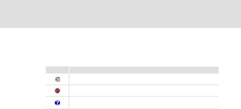
Icon Function
Starts the PLC program/application
Stops the PLC program/application
Displays help topics
OTip!
If you position the mouse pointer for a short time over an icon, a "tool tip" will be displayed with information about the corresponding function.
4.4Function area
The function area shows all presently available functions in form of icons. The functions can be activated by a mouse click.
4.5Dialog area
The dialog area displays input dialogs, buttons and text fields with additional information about the active function.
4.6Status bar
The status bar indicates the communication status (online/offline) and the device address. r For Lenze PLCs, the PLC program status is indicated as well.
r For L-force 9400 Servo Drives, the application status is indicated as well.
L
DMS 4.0 EN - 07/2007 |
13 |

L-force Loader
Operation
How to configure the communication settings
5 Operation
5.1How to configure the communication settings
The Lenze DriveServer and the OPC bus server for the corresponding fieldbus are used to build up the connection with the target system.
Note!
For the configuration of the communication settings, the DriveServer must be closed.
The DriveServer is default set to the OPC bus server for the system bus (CAN).
•If you want to use a different OPC bus server for communication, use the DriveServer configurator to add this bus server to the DriveServer.
DriveServer
For the configuration of the DriveServer, the DriveServer configurator of the »L-force Loader« is used. The DriveServer configurator is activated via Options DriveServer configurator....
OTip!
For detailed information on the DriveServer, please refer to the DriveServer documentation.
OPC bus server for system bus (CAN)
For the configuration of the system bus (CAN) communication settings, the system bus configurator of the »L-force Loader« is used. The system bus configurator is activated via
Options System bus configurator....
OTip!
The diagnostics function of the system bus configurator can, for instance, be used to check that the PC system bus adapter is working properly.
For detailed information on the system bus configurator, please refer to the CAN Communication Manual and to the Online Help of the system bus configurator.
14 |
DMS 4.0 EN - 07/2007 |
L
Loading...