


 Loading...
96M0558
Instruction
Manual
High-speed, High-Accuracy
Digital Displacement Sensor
EX-V Series

Safety Precautions
This instruction manual describes the operation and function of the EX-V. Read this manual carefully to ensure safe use and maximum performance from your EX-V.
Symbols
The following symbols alert you to important messages. Be sure to read these messages carefully.
|
WARNING |
Failure to follow instructions may lead to injury. (electric |
|
shock, burn, etc.) |
|
|
|
Failure to follow instructions may lead to product damage. |
|
CAUTION |
|
|
|
Provides additional information on proper operation. |
|
||
Note: |
||
General precautions
•At startup and during operation, be sure to monitor the functions and performance of the EX-V.
•We recommend that you take substantial safety measures to avoid any damage in the event a problem occurs.
•Do not open or modify the EX-V or use it in any way other than described in the specifications.
•When the EX-V is used in combination with other instruments, functions and performance may be degraded, depending on operating conditions and the surrounding environment.
•Do not use the EX-V for the purpose of protecting the human body.
i
Warning and cautions specific to the EX-V Series
Operating environment
For optimum performance of the EX-V, always maintain a proper operating environment.
To prevent malfunction, do not install the EX-V in the following places:
CAUTION
• Places directly exposed to sunlight.
• Places where the ambient temperature drops below 0°C or exceeds 50°C.
• Places where the relative humidity drops below 35% or exceeds 85%.
• Places where temperature fluctuations may cause condensation.
• Places where the EX-V may be exposed to corrosive or flammable gas.
• Places exposed to airborne dust or corrosive substances such as salt or metal particles.
• Places where the EX-V may be subjected to vibration or impact.
• Places where water, oil or chemicals may splash the EX-V .
• Places where the EX-V may be affected by noise interference.
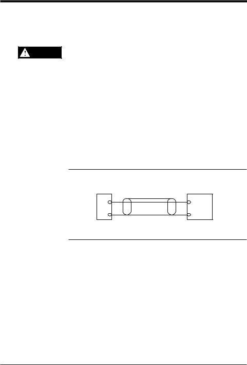
Connecting the EX-V to analog input equipment
Take the following countermeasures to prevent the EX-V from malfunctioning due to noise interference.
Note 1: Use a 1-core shielded cable for the output line. When using an analog voltage signal, do not use a cable longer than 10 m. If the cable needs to be longer than 10 m, convert the voltage signal into a current signal.
1-core shielded cable |
Various types of |
Analog |
display equipment |
voltage |
|
output |
Input |
EX-V |
|
0 V |
0V |
Note 2: Keep the wiring and connection cables separate.
Note 3: Isolate the wiring and connection cables from high-voltage or power lines; otherwise noise may cause the EX-V to malfunction.
96M0558 |
ii |
|

MEMO
iii

How this manual is organized
Chapter 1 |
|
Preparation |
|
|
|
|
|
|
||
|
|
|
||||||||
|
|
Describes the package contents, and explains the mounting and adjusting proce- |
||||||||
|
|
dures of the controller and sensor head. |
||||||||
|
|
|
|
|
||||||
Chapter 2 |
|
Quick Guide to Basic Mode Operation |
|
|||||||
|
|
Explains the kinds of the measurement modes and the selection procedure. |
||||||||
|
|
Selecting the mode best suited to your detection purpose allows you to quickly |
||||||||
|
|
operate the sensor by easy setting. |
||||||||
|
|
|
|
|
|
|
|
|||
Chapter 3 |
|
Use of Common Functions |
|
|
|
|||||
|
|
Explains the functions common to the respective modes and the setting |
||||||||
|
|
procedure. |
||||||||
|
|
|
|
|
|
|
|
|
||
Chapter 4 |
|
Use of Data Processing Functions |
|
|
||||||
|
|
Explains the setting and operation procedures of the respective functions. |
||||||||
|
|
|
|
|
|
|
|
|
|
|
Chapter 5 |
|
Troubleshooting |
|
|
|
|
|
|||
|
|
Explains the error messages displayed when an error has occurred, and |
||||||||
|
|
countermeasures to be taken. |
||||||||
|
|
|
|
|
|
|
||||
Chapter 6 |
|
Specifications and Dimensions |
|
|
||||||
|
|
Read as necessary. |
||||||||
|
|
|
|
|
|
|
|
|
|
|
|
|
Index |
|
|
|
|
|
|
|
|
|
|
Read as necessary. |
||||||||
|
|
|
|
|||||||
|
|
Warranties |
|
|||||||
iv

Contents
Chapter 1 |
Preparation |
|
|
|
1.1 |
Checking the Package Contents .......................................................... |
2 |
|
1.2 |
Part Names and Functions .................................................................... |
3 |
|
1.3 |
Terminal Names and Connections ....................................................... |
4 |
|
1.4 |
Input/output Circuits .............................................................................. |
5 |
|
1.5 |
Mounting ................................................................................................. |
6 |
|
1.5.1 |
Mounting and dismounting the controller .................................................. |
6 |
|
1.5.2 |
Mounting the sensor head ........................................................................ |
7 |
|
1.6 |
Adjustment ............................................................................................. |
9 |
|
1.6.1 |
Connection ................................................................................................ |
9 |
|
1.6.2 |
Adjusting the output characteristics .......................................................... |
9 |
|
|
|
|
Chapter 2 |
Quick Guide to Basic Mode Operation |
|
|
|
2.1 |
...........................................................................Measurement Modes |
12 |
|
2.1.1 |
Bottom-dead-center mode ...................................................................... |
12 |
|
2.1.2 |
Eccentricity/vibration mode ..................................................................... |
12 |
|
2.1.3 |
Thickness/gap mode ............................................................................... |
13 |
|
2.1.4 |
Manual mode .......................................................................................... |
13 |
|
2.2 |
Quick Guide to Basic Mode Operation .............................................. |
14 |
|
2.2.1 |
Setting the bottom-dead-center mode .................................................... |
14 |
|
2.2.2 |
Setting the eccentricity/vibration mode ................................................... |
18 |
|
2.2.3 |
Setting the thickness/gap mode .............................................................. |
21 |
|
2.3 |
Auto-Zero Function .............................................................................. |
24 |
|
2.4 |
Tolerance Limit Value Setting ............................................................. |
25 |
2.5Checking the Tolerance Limit Values
(Calling the tolerance limit values) ..................................................... |
27 |
Chapter 3 Use of Common Functions
3.1 |
Table of Functions and Function Numbers ....................................... |
30 |
|
3.2 |
Function Setting Flow ......................................................................... |
|
31 |
3.2.1 |
Selecting the function using the |
key .................................................. |
31 |
3.2.2 |
Display scaling function [E] ..................................................................... |
|
33 |
3.2.3 |
Monitor (analog voltage) output setting function [F] ................................ |
36 |
|
3.2.4 |
Digits function/decimal point function [g]................................................. |
39 |
|
3.2.5 |
Offset function [x] .................................................................................... |
|
40 |
3.2.6 |
Output form selection function [I] ........................................................... |
|
42 |
3.2.7 |
Panel-lock function [j]............................................................................. |
|
43 |
v

Chapter 4 |
Use of Data Processing Functions |
|
|
|
4.1 |
Table of Data Processing Functions .................................................. |
46 |
|
4.2 |
Details of Bottom-dead-center Mode ................................................. |
47 |
|
4.2.1 |
No. of averaging measurements/Digital filter [A] ..................................... |
47 |
|
4.2.2 |
Measurement type [b] ............................................................................. |
49 |
|
4.2.3 |
Measurement period [[] .......................................................................... |
53 |
|
4.2.4 |
Previous value comparison function [d] .................................................. |
56 |
|
4.3 |
Details of Eccentricity/vibration Mode .............................................. |
57 |
|
4.3.1 |
No. of averaging measurements/Digital filter [A] ..................................... |
57 |
|
4.3.2 |
Measurement type [b] ............................................................................. |
57 |
|
4.3.3 |
Measurement period [[] .......................................................................... |
61 |
|
4.4 |
Details of Thickness/gap Mode ......................................................... |
64 |
|
4.4.1 |
No. of averaging measurements/Digital filter [A] ..................................... |
64 |
|
4.4.2 |
Measurement type [b] ............................................................................. |
64 |
|
4.4.3 |
Measurement period [[] .......................................................................... |
69 |
|
4.4.4 |
Inverse/normal display function [d] ......................................................... |
73 |
|
4.5 |
Details of Manual Mode ....................................................................... |
74 |
|
4.5.1 |
No. of averaging measurements/Digital filter [A] ..................................... |
74 |
|
4.5.2 |
Measurement type [b] ............................................................................. |
74 |
|
4.5.3 |
Measurement period [[] .......................................................................... |
84 |
|
4.5.4 |
Previous value comparison function [d] .................................................. |
84 |
|
4.6 |
Hysteresis Setting ................................................................................ |
85 |
|
4.7 |
Initialization .......................................................................................... |
86 |
Chapter 5 |
Troubleshooting |
|
|
|
5.1 |
Error Messages .................................................................................... |
88 |
|
5.2 |
Troubleshooting List ........................................................................... |
89 |
|
|
|
|
Chapter 6 |
Specifications and Dimensions |
|
|
|
6.1 |
.......................................................................................Specifications |
92 |
|
6.2 |
Characteristics Charts ......................................................................... |
93 |
|
6.3 |
Minimum Input Time and Output Response Time ............................ |
96 |
|
6.4 |
Dimensions ........................................................................................... |
98 |
|
|
|
|
|
Index |
|
|
|
Index |
.............................................................................................................. |
101 |
|
|
|
|
|
Warranties |
|
|
|
WARRANTIES AND DISCLAIMERS ............................................................ |
109 |
|
vi

Quick Index by Function/Operation
This index helps you quickly find proper EX-V function/operation according to your purpose.
Select action or operation you need to find the proper page and description.
Display/Setup
|
Function/Operation |
Description |
Page |
|
|
|
|
|
|
|
Viewing tolerance values for OK/NG |
Calling the tolerance limit values |
27 |
|
|
|
|
|
|
|
Setting tolerance values for OK/NG |
Tolerance Limit Value Setting |
25 |
|
|
|
|
||
|
|
|
|
|
|
Ignoring fluctuation at start-up or |
Previous value comparison function |
56 |
|
|
temperature drift |
|
||
|
|
|
|
|
|
|
|
|
|
|
Inputting timing signal from external |
Timing input |
4 |
|
|
device |
|
||
|
|
|
|
|
|
|
|
|
|
|
Viewing outline of setup process of |
Outline of setup process for each |
46 |
|
|
each function |
function using [SET] key |
|
|
|
|
|
||
|
|
|
|
|
|
Viewing list of all function numbers |
Table of Functions and Function |
30, 46 |
|
|
and details |
Numbers |
|
|
|
|
|
||
|
|
|
|
|
|
Initializing all settings to factory |
Initialization |
86 |
|
|
defaults |
|
||
|
|
|
|
|
|
|
|
|
|
|
Locking front panel operation |
Panel-lock function |
43 |
|
|
|
|
|
|
|
Checking measurement period during |
Strobe output |
4 |
|
|
adjustment |
|
|
|
|
|
|
|
|
|
Triggering without timing sensors |
Internal trigger |
53 |
|
|
|
|
|
|
|
Moving decimal point to change unit |
Decimal point function |
39 |
|
|
|
|
|
|
|
Changing measuring time for internal |
Sampling delay |
53 |
|
|
trigger |
|
|
|
|
|
|
|
|
|
Deciding measurement averaging |
|
|
|
|
time according to the input/control |
No. of averaging measurements |
48 |
|
|
method |
|
|
|
|
|
|
|
|
|
Setting gain/offset value for achieving |
Monitor (analog voltage) output setting |
36 |
|
|
desired display value against input |
function |
|
|
|
value |
|
|
|
|
|
|
|
|
|
|
|
|
|
|
Setting off-delay timer for comparator |
Off-delay output |
42 |
|
|
output signal |
|
|
|
|
|
|
|
|
|
Holding comparator output signal |
Hold output |
42 |
|
|
|
|
|
|
|
Selecting comparator tolerance value |
External setting input |
12 |
|
|
from external device |
|
|
|
|
|
|
|
|
|
Changing display value digit to 4 |
Digits function |
39 |
|
|
digits |
|
||
|
|
|
|
|
|
|
|
|
|
|
Adding/subtracting desired value |
Offset function |
40 |
|
|
to/from display value |
|
||
|
|
|
|
|
|
|
|
|
|
|
Quickly changing (resetting) display |
Auto-Zero Function |
24 |
|
|
value to "0" |
|
||
|
|
|
|
|
|
|
|
|
|
|
Disabling comparator output during |
|
|
|
|
press machine bottom-dead-center |
Output disable input |
14 |
|
|
adjustment |
|
|
|
|
|
|
|
|
|
Setting monitor voltage output |
Monitor (analog voltage) output setting |
36 |
|
|
independent from display value |
function |
|
|
|
|
|
||
|
|
|
|
|
|
|
|
|
|
vii

Measurement
Function/Operation |
|
Description |
Page |
|
Numbers 1. and 2. indicate the order of setup. |
||||
|
|
|||
Measuring thickness |
1. |
Setting the thickness/gap mode |
21 |
|
2. |
Setting the tolerance limit |
|||
|
|
|||
|
|
|
|
|
Checking die closure failure due to |
1. |
Setting the measurement mode in |
|
|
|
initial setting (Normal mode). |
76 |
||
foreign matter |
|
|||
2. |
Setting the tolerance limit |
|
||
|
|
|||
Measuring height of low profile |
1. |
Setting the measurement type to |
|
|
|
Intermittent in Thickness/Gap mode. |
21 |
||
portion |
|
|||
2. |
Setting the tolerance limit |
|
||
|
|
|||
|
|
|
|
|
Measuring displacement of origin |
1. |
Setting the measurement mode in |
|
|
|
initial setting(Normal mode). |
76 |
||
position |
|
|||
2. |
Setting the tolerance limit |
|
||
|
|
|||
|
|
|
|
|
|
1. |
Setting the measurement type to\ |
|
|
Detecting failure in forming with |
|
Limited bottom-dead-center to |
|
|
|
measure the mold clearance during |
14 |
||
injection molding machine |
|
|||
|
closure. |
|
||
|
|
|
||
|
2. |
Setting the tolerance limit |
|
|
|
|
|
|
|
Detecting chucking error |
1. |
Setting the eccentricity/vibration mode |
18 |
|
2. |
Setting the tolerance limit |
|||
|
|
|||
|
|
|
|
|
Measuring vibration of base plate |
1. |
Setting the eccentricity/vibration mode |
18 |
|
2. |
Setting the tolerance limit |
|||
|
|
|||
|
|
|
|
|
Measuring runout of cutting tool |
1. |
Setting the eccentricity/vibration mode |
18 |
|
2. |
Setting the tolerance limit |
|||
|
|
|||
|
|
|
|
|
Inputting comparator tolerance |
|
|
25 |
|
|
|
|
|
|
Measuring eccentricity of roller |
1. |
Setting the eccentricity/vibration mode |
18 |
|
2. |
Setting the tolerance limit |
|||
|
|
|||
Installation
Function/Operation |
Description |
Page |
|
|
|
|
|
Embedding sensor into metal material |
Flush-mount |
7 |
|
|
|||
|
|
|
|
Installing multiple sensors in close |
Mutual interference |
8 |
|
position |
|||
|
|
||
|
|
|
|
Extending sensor cable |
Do not extend. |
8 |
|
|
|
|
|
Cutting sensor cable |
Do not cut. |
8 |
|
|
|
|
viii

ix
Chapter 1
Preparation
Describes the package contents, and explains the mounting and adjusting procedures of the controller and sensor head.
1.1 |
Checking the Package Contents ......................................... |
2 |
1.2 |
Part Names and Functions .................................................. |
3 |
1.3 |
Terminal Names and Connections ...................................... |
4 |
1.4 |
Input/output Circuits ............................................................ |
5 |
1.5 |
Mounting ................................................................................ |
6 |
1.5.1 |
Mounting and dismounting the controller ................................. |
6 |
1.5.2 |
Mounting the sensor head ....................................................... |
7 |
1.6 |
Adjustment ............................................................................ |
9 |
1.6.1 |
Connection ............................................................................... |
9 |
1.6.2 |
Adjusting the output characteristics ......................................... |
9 |
Chapter 1 Preparation
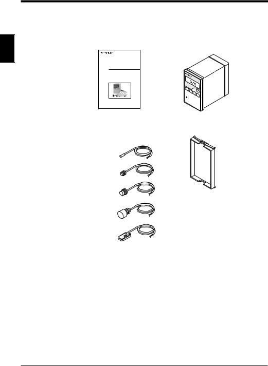
1.1Checking the Package Contents
The EX-V series package includes the following parts and equipment. Check that all the parts and equipment are included in the package.
1 |
• Instruction manual: 1 |
• Controller: 1 |
|
|
|
|
Instruction |
|
|
Manual |
|
|
High-speed, High-Accuracy |
|
|
Digital Displacement Sensor |
|
|
EX-V Series |
|
• Sensor head: |
• Panel mounting frame: 1 |
Ordered one of the following |
|
EX-305V |
|
EX-110V
EX-416V
EX-422V
EX-614V
2
Chapter 1 Preparation
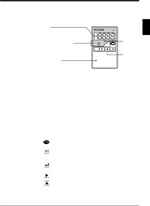
1.2Part Names and Functions
This section explains the part names and functions.
■ Controller
Display
Displays the measured value. The value is displayed in green when the measured value is within the tolerance range. The value is displayed in red when the measured value is out of the tolerance range.
Comparator output indicators
Illuminates when the comparator output (HIGH, GO, LOW) is turned on.
Indicates the type of displayed tolerance limit value when setting or calling the tolerance limit value.
HIGH  TIM
TIM
GO
LOW
CALL
SET
FUNC UTILITY MODE CALIB
POWER
1
TIMING input indicator
Illuminates when a timing signal is input.
Operation keys
POWER indicator
Illuminates green:
When operation is normally performed
Illuminates red:
When the control output is reset to OFF
■ Displays and functions
Display |
Function |
|
|
|
|
Numeric value (±19.999) |
The operation result is displayed as a numeric |
|
value. |
||
|
||
|
|
|
FFFF (HIGH output: ON, Analog voltage |
"FFFF" is displayed when the operation result is |
|
output: +5.8 V) |
above the display range. |
|
|
|
|
-FFFF (LOW output: ON, Analog voltage |
"-FFFF" is displayed when the operation result |
|
output: -5.8 V) |
is below the display range. |
|
|
|
|
- - - - (HI, GO and LOW outputs: OFF, |
There is no operation result to be displayed. |
|
Analog voltage output: 0V) |
||
|
||
|
|
■ Operation keys
Key |
|
Function |
|
|
|
|
• Resets the value on the display to "0000" (zero). |
|
|
|
If the offset function is selected, the value on display is reset to the offset |
|
|
value. ( For details, see page 40.) |
|
• |
Initializes all function settings during function setting. |
|
• |
Calls the tolerance limit setting mode. ( For details, see page 25.) |
FUNC |
• Calls the function setting modes ("A" to "D") to perform setting of each |
|
|
function. ( For details, see pages 48, 57, 64, and 74.) |
|
|
|
|
|
• Calls the adjustment mode. |
|
CALL |
• Saves each setting. |
|
|
• Cancels each error message. |
|
CALIB |
• Calls the tolerance limit value during measurement. |
|
|
( For details, see page 27.) |
|
|
• |
Selects each setting. |
UTILITY |
• Calls the common function selection modes ("E" to "J"). |
|
|
|
|
|
|
|
|
• Sets each function number. |
|
MODE |
• Calls the measurement mode. |
|
|
|
|
3

Chapter 1 Preparation
1.3Terminal Names and Connections
This section explains the terminal names and functions.
1 |
|
HIGH 10 |
20 |
ALARM |
||
|
|
|||||
|
|
GO |
9 |
19 |
STROBE |
|
|
|
LOW |
8 |
18 |
GND2 |
|
|
|
GND1 |
7 |
17 |
EXT1 |
|
|
|
TIMING |
6 |
16 |
EXT2 |
|
|
HOLD RESET |
5 |
15 |
SYNC |
||
|
|
ZERO |
4 |
14 |
MONITOR |
|
|
OUTPUT DISABLE |
3 |
13 |
0V |
||
|
|
– |
2 |
12 |
Sensor head |
|
|
24V DC |
|||||
|
|
|
|
|||
|
|
+ |
1 |
11 |
Terminal block |
|
|
|
|
|
|
||
|
No. |
Terminal name |
|
Function |
||
|
1, 2 |
Power supply |
24 VDC ±10% |
|||
|
3 |
Comparator output |
Resets the comparator output to OFF when this terminal is |
|||
|
disable input |
short-circuited to the grounding terminal. |
||||
|
|
|||||
|
|
|
|
Resets the value on the display to "0000" (offset value |
||
|
4 |
Auto-zero input |
when the offset function is selected) when this terminal is |
|||
|
|
|
|
short-circuited to the grounding terminal. |
||
|
|
|
|
When this terminal is short-circuited to the grounding |
||
|
5 |
Hold-reset input |
terminal: 1. Cancels the hold state of the open collector |
|||
|
|
|
|
output. 2. Resets each hold mode data. |
||
|
6 |
Timing input |
Inputs a timing signal when this terminal is short-circuited |
|||
|
to the grounding terminal. |
|||||
|
|
|
|
|||
|
7 |
Grounding |
|
|
||
|
8 |
LOW output |
Outputs when the displayed value is lower than the LOW |
|||
|
limit value. |
|||||
|
|
|
|
|||
|
9 |
GO output |
Outputs when the displayed value is within the tolerance |
|||
|
range. |
|||||
|
|
|
|
|||
|
10 |
HIGH output |
Outputs when the displayed value is higher than the HIGH |
|||
|
limit value. |
|||||
|
|
|
|
|||
|
11, 12 |
Sensor head |
Connects the sensor head. |
|||
|
connection |
|||||
|
13, 14 |
Monitor (analog |
Outputs analog voltage (-5 to +5 V) in proportion to the |
|||
|
|
voltage) output |
displayed value. |
|||
|
15 |
Synchronous input |
Stops sensor head oscillation and holds the output when |
|||
|
this terminal is short-circuited to the grounding terminal. |
|||||
|
|
|
|
|||
|
16, 17 |
External setting |
Calls the preset four kinds of tolerance limit values. This |
|||
|
input |
|
input is enabled when the panel-lock function is set to ON. |
|||
|
18 |
Grounding |
|
|
||
|
|
|
|
Turns ON during the sampling period. This terminal is |
||
|
19 |
Strobe output |
enabled only when the internal trigger function is used. |
|||
|
|
|
|
(N.O.) |
|
|
|
20 |
Alarm output |
Outputs when an abnormal state occurs. (N.C.) |
|||
CAUTION |
Since the power GND, GND1 and GND2 are connected through choke coils, |
|||||
make sure so that no potential difference develops. |
||||||
|
||||||
4
Chapter 1 Preparation
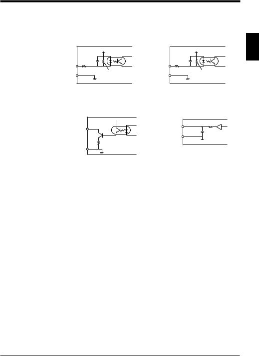
1.4 Input/output Circuits
Input circuit
TIMING, HOLD RESET
+24 V |
3 kΩ |
IN |
470 Ω |
GND |
ZERO, EXT1•2, OUTPUT DISABLE |
|
SYNC |
1 |
+24 V |
|
10 kΩ |
|
IN |
|
3 kΩ |
|
GND |
|
Output circuit
HIGH, GO, LOW, STROBE
NPN Output |
GND |
NPN open-collector, 40 V, 100 mA max.
MONITOR (analog voltage) output
100 Ω |
Output |
0 V |
0 V |
5
Chapter 1 Preparation
1.5Mounting
This section explains the mounting procedure for the controller and sensor head and the wiring connections.
1 |
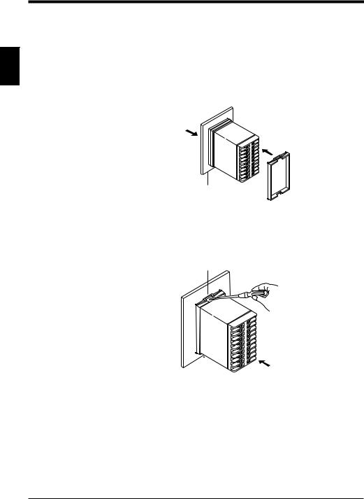
1.5.1 Mounting and dismounting the controller |
|
Mounting |
||
|
||
|
Insert the controller from the front of the panel and fix it using the panel mounting |
|
|
||
|
frame. |
1. Insert the controller. |
2. Fix the controller using the |
|
panel mounting frame. |
||
|
Panel
 Panel mounting frame
Dismounting
While raising the catches at sections 1 and 2 with a flat blade screwdriver, push the controller forward from the back.
1
|
|
Push the controller forward. |
|
2 |
|||
|
|||
6
Chapter 1 Preparation
1.5.2 Mounting the sensor head
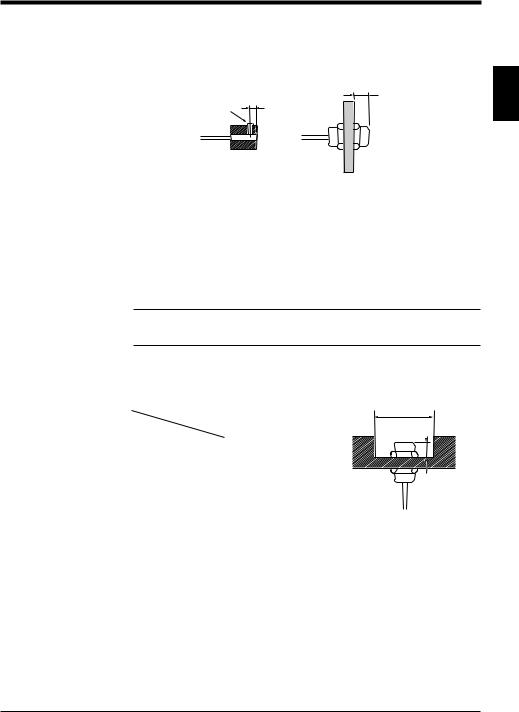
Mounting
•Tighten the EX-305V set screw and EX-110V nut away from the tip of the sensor head as shown in the figure.
8 mm min.
|
5 mm min. |
M3 set screw |
|
EX-305V |
EX-110V |
1
•Referring to the measuring distance in the table below, determine the distance between the tip of the sensor head and target.
Model |
Measuring distance (mm) |
|
|
EX-305V |
1 |
|
|
EX-110V |
2 |
|
|
EX-416V |
5 |
|
|
EX-422V |
10 |
|
|
EX-614V |
4 |
|
|
Note: After making the adjustment, do not change the position of the nut or screw. If the position is changed, the output characteristics may change even when the nut or screw is positioned in the range shown in the figure.
Flush-mounting
To flush-mount the sensor head in a metal base, follow the guidelines given in the table below.
Distance (mm) |
A |
B |
|
Model |
|||
|
|
||
|
|
|
|
EX-305V |
10 |
9 |
|
|
|
|
|
EX-110V |
12 |
9 |
|
|
|
|
|
EX-416V |
35 |
10 |
|
|
|
|
|
EX-422V |
55 |
20 |
|
|
|
|
|
EX-614V |
16 x 32 |
5 |
|
|
|
|
øA
B 
*The table above shows the dimensions to use when the metal base is iron.
*The table above shows the dimensions to satisfy the specifications when the sensor head is flush-mounted after the output characteristics have been adjusted with no metal present around the head.
7
Chapter 1 Preparation
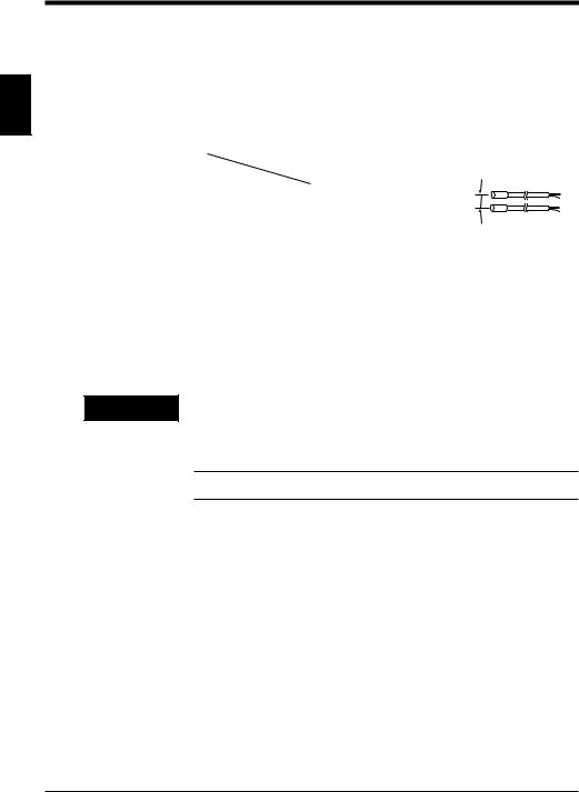
When mounting two or more sensor heads of the same model in parallel
|
• The sensor may not output the correct voltage due to mutual interference. Make |
|
sure that the distance between sensor heads adjacent to each other is larger |
|
than the values shown in the table below. (This allows the display resolution |
|
specification to be satisfied when the number of measurements to average is |
1 |
"64".) |
• When two sensor heads are mounted in parallel, mutual interference can be |
|
|
prevented by alternately oscillating the sensor heads using the synchronous |
input terminal ( page 4).
Distance (mm) |
Parallel mounting |
|
|
Model |
|
||
|
|
||
|
|
|
|
EX-305V |
80 |
Parallel mounting |
|
|
|
||
EX-110V |
300 |
||
|
|||
|
|
|
|
EX-416V |
650 |
|
|
|
|
|
|
EX-422V |
310 |
|
|
|
|
|
|
EX-614V |
245 |
|
|
|
|
|
Tightening torque

 CAUTION
To tighten the EX-305V set screw, apply a torque of 0.2 N•m or less.
To tighten the nut of the other sensor heads, apply a torque shown in the table below or less.
EX-110V |
EX-416V |
EX-422V |
|
|
|
10 N• m max. |
20 N• m max. |
10 N• m max. |
|
|
|
•If the applied tightening torque exceeds the specified one, the sensor head may be deformed or malfunction.
•If the sensor cable is installed in the same conduit as high voltage lines or power lines, the sensor may malfunction. Be sure to keep the wiring separate.
Note: Do not change the sensor cable length (3 m). If the cable is extended or cut, the characteristics will change.
8

Chapter 1 Preparation
1.6 |
Adjustment |
|
|
|
Though the EX-V series has been factory-adjusted, follow the procedure described |
|
|
|
below to adjust the sensor using your actual target in order to satisfy the |
|
|
|
specifications. When the sensor head has been replaced, be sure to make this |
1 |
|
|
adjustment. |
||
1.6.1 |
Connection |
||
|
|||
|
|
|
1.Connect the core and shielding wires of the sensor head to sensor head connection terminals 11 and 12 of the controller.
2.After making the connection,
connect the power supply cable to 10 |
20 |
power supply terminals 1 and 2. |
19 |
9 |
The POWER indicator on the controller illuminates, and the sensor enters the operation state.
–
24V DC
+
8 |
18 |
|
7 |
17 |
|
6 |
16 |
|
5 |
15 |
|
4 |
14 |
|
3 |
13 |
|
2 |
12 |
Sensor head |
1 |
11 |
|
Terminal block
Note: Let the sensor warm up for 30 minutes or more after supplying power to it, and then start the adjustment.
1.6.2Adjusting the output characteristics
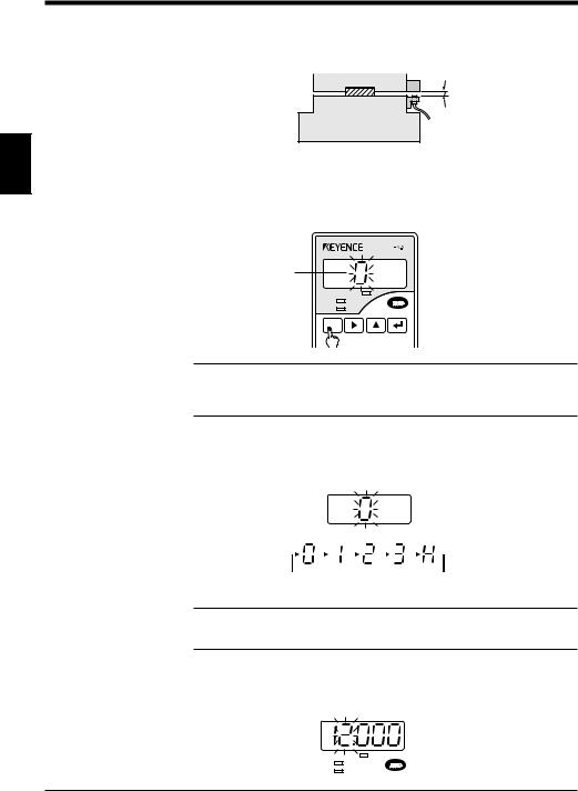
1.Press the  key for at least 2 seconds.
The sensor displays "0" and enters the adjustment mode.
HIGH  TIM
TIM
GO
LOW
CALL
SET
FUNC UTILITY MODE |
CALIB |
2.With no metal object present around the sensor head, press the  key. The sensor displays "1" and moves to the next setting step.
Note 1: Do not touch the metal area of the sensor head with your hand.
Note 2: Make sure that no metal object is present within a radius of 15 centimeters around the sensor head.
9
Chapter 1 Preparation
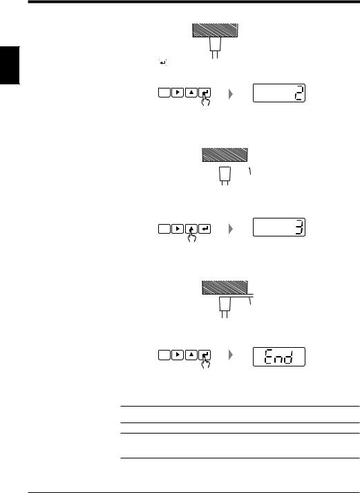
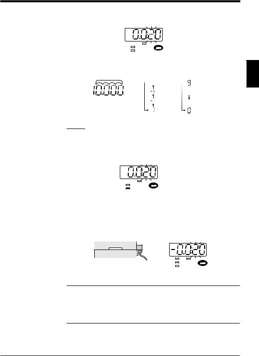
3. Bring the sensor head in contact with the target.
1 |
4. Press the |
key. |
|
The sensor displays "2" and moves to the next setting step.
CALL
SET
5.Move the sensor head.
Move the sensor head so that the distance between the sensor head and target is the full scale of the measuring distance (maximum distance) of the sensor head.
 Full scale
6.Press the  key.
key.
The sensor displays "3" and moves to the next setting step.
CALL
SET
7.Move the sensor head.
Move the sensor head so that the distance between the sensor head and target is half the measuring distance (half scale).
Half scale
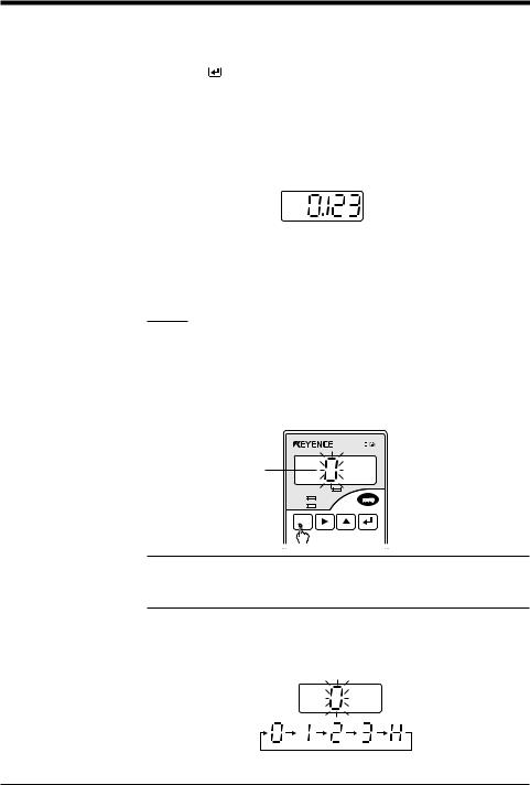
8.Press the  key.
key.
The sensor displays "End".
CALL
SET
9.Press the  key to complete the adjustment. The sensor starts measurement.
Reference: To stop the adjustment, press the  key. Then, the sensor starts measurement without making the adjustment.
Note: If the distance between the sensor head and target is improperly adjusted during the adjustment, "Err 6" is displayed. Press the  key to cancel the error, and then readjust the distance.
10
Chapter 2
Quick Guide to Basic Mode Operation
Explains the kinds of the measurement modes and the selection procedure. Selecting the mode best suited to your detection purpose allows you to quickly operate the sensor by easy setting.
2.1 |
Measurement Modes ........................................................... |
12 |
2.1.1 |
Bottom-dead-center mode ..................................................... |
12 |
2.1.2 |
Eccentricity/vibration mode .................................................... |
12 |
2.1.3 |
Thickness/gap mode .............................................................. |
13 |
2.1.4 |
Manual mode ......................................................................... |
13 |
2.2 |
Quick Guide to Basic Mode Operation .............................. |
14 |
2.2.1 |
Setting the bottom-dead-center mode ................................... |
14 |
2.2.2 |
Setting the eccentricity/vibration mode .................................. |
18 |
2.2.3 |
Setting the thickness/gap mode ............................................. |
21 |
2.3 |
Auto-Zero Function ............................................................. |
24 |
2.4 |
Tolerance Limit Value Setting ............................................ |
25 |
2.5Checking the Tolerance Limit Values
(Calling the tolerance limit values) .................................... |
27 |
Chapter 2 Quick Guide to Basic Mode Operation
2.1 |
Measurement Modes |
||
|
|
The EX-V series provides the following four measurement modes: "Bottom-dead- |
|
|
|
center mode", "Eccentricity/vibration mode", "Thickness/gap mode" (which are |
|
|
|
basic modes for quick operation), and "Manual mode" (which allows users to |
|
|
|
perform setting as desired). This section explains the major functions of each |
|
|
|
mode. |
|
|
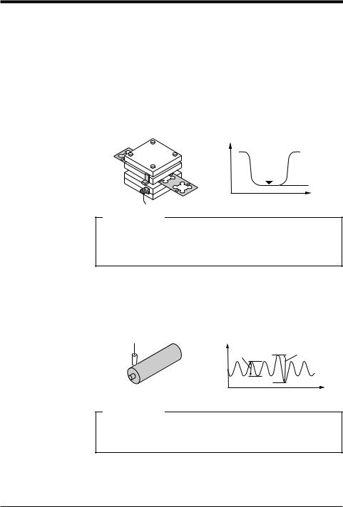
2.1.1 Bottom-dead-center mode |
||
2 |
|||
|
This mode is used to measure the displacement of the origin position of a machine |
||
|
with stroke movements such as a press. When the displacement of the bottom |
||
|
|
dead center or origin position is out of the preset tolerance range, the sensor |
|
|
|
outputs an Alarm signal. |
|
|
|
||
Displacement
Bottom dead center
Displayed value
Time
Major applications
•Detecting the bottom dead center position of a press
•Detecting the bottom dead center position of a press-fit machine
•Detecting the bottom dead center position of a welding machine
•Pressure control for a injection molding machine
•Measuring the depth of the recess on a piston head
2.1.2Eccentricity/vibration mode
This mode is used to measure the roller eccentricity or abnormal machine vibration. When the amplitude of the runout or vibration is larger than the preset tolerance limit value, the sensor outputs an Alarm signal.
Displacement
OK |
NG |
|
Time
Major applications
•Measuring roller eccentricity
•Measuring surface plate runout
•Detecting runout due to improper chucking
•Measuring drill bit eccentricity
12
Chapter 2 Quick Guide to Basic Mode Operation
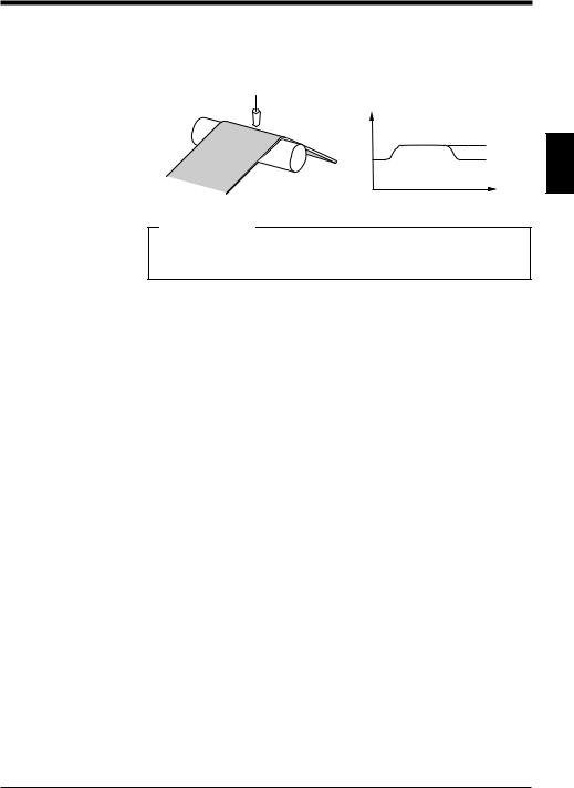
2.1.3 Thickness/gap mode
This mode is used to measure target thickness or gap with a direct reading value. When the thickness or gap is larger or smaller than the preset upper or lower value for the tolerance limit, the sensor outputs an Alarm signal.
Displacement |
Displayed value |
|
|
|
Time |
Major applications
•Measuring hoop material thickness
•Checking grindstone abrasion
•Thickness control during polishing ceramic components
2.1.4 Manual mode
In addition to the modes above, the manual mode is available. The manual mode provides the following six data processing modes to allow adaptable measurement. For details, see pages that describe each data processing mode.
Data processing mode |
Function |
Reference |
|
page |
|||
|
|
||
|
|
|
|
Normal measurement |
Displays/outputs the measured value |
76 |
|
continuously. |
|||
|
|
||
|
|
|
|
Peak hold |
Measures the maximum value during a |
76 |
|
specified period. |
|||
|
|
||
|
|
|
|
Bottom hold |
Measures the minimum value during a specified |
78 |
|
period. |
|||
|
|
||
|
|
|
|
Peak-to-peak hold |
Measures the difference between the maximum |
79 |
|
and minimum values during a specified period. |
|||
|
|
||
|
|
|
|
Sample hold |
Measures the value at a specified time. |
81 |
|
|
|
|
|
Average hold |
Measures the simple average of measured |
82 |
|
values during a specified period. |
|||
|
|
||
|
|
|
2
13
Chapter 2 Quick Guide to Basic Mode Operation
2.2 Quick Guide to Basic Mode Operation
This section describes the major measurement modes and an easy setting method.
2.2.1 Setting the bottom-dead-center mode
|
The following example explains how to mount the EX-V series to a press. |
|
|
The basic operation is the same when mounting the EX-V series to other devices. |
|
|
||
2 |
Be sure to adjust the output characteristics before performing the following proce- |
|
dure. ( Refer to page 9.) |
||
|
||
|
1. Secure the sensor head to the lower die of the press. |
|
|
• Referring to the figure below, prepare the sensor head mounting jig and a |
|
|
target. |
|
|
• Refer to pages 7 and 8 for the position of the sensor head nut and the tightening torque. |
Target
Sensor head
Note: Be sure to use an IRON target with sufficient area for detection. ( p.95)
Reference: When the comparator output is already connected to the emergency stop or another input for the facility, short-circuit the OUTPUT DISABLE input (terminal 3) and grounding terminal (terminal 7) to disable the comparator output before making the adjustment.
*After making the adjustment, be sure to disconnect these terminals to enable the comparator output.
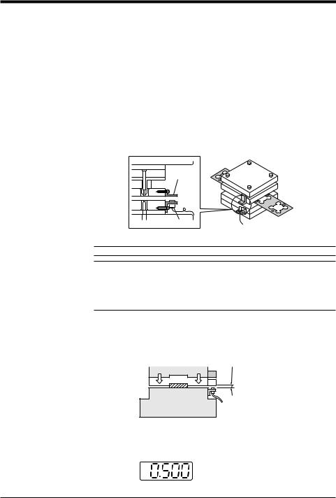
2.Adjust the distance between the sensor head and target.
Move the press an inch at a time and lower the stripper (or upper die) to the bottom dead center position. (Refer to the figure below.)
Half the measuring range of the sensor to be used.
Stripper or upper die
Lower die
Die set
Adjust the distance between the sensor head and target so that the distance between them is about half the measuring distance when the stripper is in the bottom dead center position. The controller’s display shows a value close to the half scale.
In the case of the EX-305V, the value is close to “0.5”.
14
Chapter 2 Quick Guide to Basic Mode Operation
*The distance between the sensor head and target should be more than the full scale when the stripper is in the top dead center position.
Sensor model |
Measuring distance |
Half scale |
|
(mm) (Full scale) |
(mm) |
||
|
|||
EX-305V |
1 |
0.5 |
|
EX-110V |
2 |
1 |
|
EX-416V |
5 |
2.5 |
|
EX-422V |
10 |
5 |
|
EX-614V |
4 |
2 |
3. Press the |
key for at least 2 seconds. |
2 |
|
The sensor enters the mode setting state and displays the mode number.
Mode No
HIGH  TIM
TIM
GO
LOW
CALL
SET
FUNC UTILITY MODE CALIB
4.Press the  key to display “1” which indicates the “bottom-dead-center” mode.
• Pressing the  key changes the mode number sequentially.
Mode No. |
Measurement mode |
0 |
Manual |
1 |
Bottom-dead-cente |
2 |
Eccentricity/vibration |
3 |
Thickness/gap |
HIGH TIM
GO
LOW
 key
key
•The measurement mode is factory-set to manual.
For the initial setting of each measurement mode, refer to “4.1 Table of Data Processing Functions” on page 46.
5.Press the  key to save the measurement mode setting. The sensor returns to the measurement state.
Note: Changing the measurement mode initializes all preset values except for the tolerance limit values.
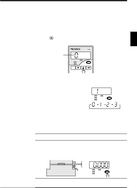
6.Activate the machine and check the bottom dead center position during normal operation. Press the [ZERO] key to set this position as the reference point.
When the [ZERO] key is pressed, “0000” appears on the measured value |
||
display. |
|
Normal bottom |
|
|
|
|
|
dead center |
|
Stripper or upper die |
|
|
Lower die |
|
|
|
HIGH TIM |
|
Die set |
GO |
|
LOW |
|
|
|
|
Reference: To compensate for the slight variation in the bottom dead center position at press startup or the influence of temperature fluctuation, refer to “Previous value comparison function [d]” on page 56.
15
Chapter 2 Quick Guide to Basic Mode Operation
7.Set the upper value for the tolerance limit.
For a press, set the threshold value to the amount of the rise of the bottom dead center due to swarf.
Upper limit value
Stripper or upper die
Lower die
Die set
2
1)Press the  key.
key.
•The sensor enters the tolerance limit setting mode.
•The setting number is displayed.
Mode No
HIGH  TIM
TIM
GO
LOW
CALL
SET
FUNC UTILITY MODE CALIB
Note: Press the  key for a short time. When the key is pressed for 2 seconds or longer, the sensor enters the function setting mode and displays “Ab[d”. If you accidentally put the sensor into the function setting mode, press the
  key again to return to the measurement state.
2)Press the  key to display the desired setting number.
•Pressing the  key changes the setting number sequentially.
•“x” indicates the hysteresis setting. ( Refer to page 85.)
 key
key
Reference: Four kinds of tolerance limit values (“0” to “3”) can be saved in the memory. The registered setting numbers can be switched using external signals. ( Refer to page 4.)
3)Press the  key.
key.
•The sensor automatically enters the HIGH limit value setting mode.
•The setting value is displayed in red and the HIGH indicator illuminates.
HIGH 
 TIM
TIM
GO
LOW
16
Chapter 2 Quick Guide to Basic Mode Operation
4)Press the  or
or  key to display the desired value.
• Pressing the  key changes the flashing digit to the right.
HIGH 
 TIM
TIM
GO
LOW
•Pressing the  key changes the value.
•All digits flash when the fifth digit and sign can be changed.
2
No setting
|
|
(1st to 4th digits) |
(5th digit) |
||
|
|
|
|
|
|
|
|
|
Example
When setting the tolerance to +20 m, specify “0020”.
5) Press the  key.
key.
The HIGH limit setting value is saved. The sensor automatically enters the LOW limit value setting mode.
HIGH 
 TIM
TIM
GO
LOW
8.Set the lower value for the tolerance limit and press the  key.
key.
•For a press, set the threshold value to the amount of the lowering of the bottom dead center due to the absence of a target.
•Set the LOW limit value using the same procedure as in steps 7 3) and 4), and press the  key to save the value.
Stripper or upper die
Lower die
|
HIGH |
|
TIM |
Die set |
GO |
|
|
LOW |
|
|
|
|
|
|
|
Note 1: The output is disabled during the tolerance limit value setting. When the output is already on, however, the output is retained.
Note 2: Pressing the  key does not save the changes if [HIGH setting value – Hysteresis] is smaller than [LOW setting value + Hysteresis]. In this case, “Err1” is displayed. Press the
  key again to cancel the error, and then specify the correct values.
17

Chapter 2 Quick Guide to Basic Mode Operation
2.2.2 Setting the eccentricity/vibration mode
The following example explains the procedure for roller eccentricity measurement.
The basic operation is the same when mounting the EX-V series to other devices. Be sure to adjust the output characteristics before performing the following procedure ( page 9).
1.Mount the sensor head to the machine.
For the sensor head mounting procedure, read "Mounting the sensor head" (pages 7 and 8).
2
Note: Be sure to use an IRON target with sufficient area for detection. ( page 95)
Reference: When the comparator output is already connected to the emergency stop or another input for the facility, short-circuit the OUTPUT DISABLE input (terminal 3) and grounding terminal (terminal 7) to disable the comparator output before making the adjustment.
*After making the adjustment, be sure to disconnect these terminals to enable the comparator output.
2.Press the  key for at least 2 seconds.
The sensor enters the mode setting state and displays the mode number.
Mode No.
HIGH  TIM
TIM
GO
LOW
CALL
SET
FUNC UTILITY MODE CALIB
3.Press the  key to display "2" which indicates the "eccentricity/vibration" mode.
• Pressing the  key changes the setting number sequentially.
Mode No. |
Measurement mode |
|
|
0 |
Manual |
|
|
1 |
Bottom-dead-center |
|
|
2 |
Eccentricity/vibration |
|
|
3 |
Thickness/gap |
|
|
HIGH 
 TIM
TIM
GO
LOW
 key
key
18
Chapter 2 Quick Guide to Basic Mode Operation
•The measurement mode has been factory-set to manual.
For the initial setting of the functions for each measurement mode, refer to "4.1 Table of Data Processing Functions" (page 46).
4. |
Press the |
key to save the measurement mode setting. |
|
||
|
The sensor returns to the measurement state. |
|
|||
|
|
|
|||
Note: Changing the measurement mode initializes all preset values except for the |
|
||||
tolerance limit values. |
|
|
|||
2 |
|||||
5. |
Activate the machine and check the runout value during normal operation. |
||||
|
|||||
|
The value displayed in this step is the runout per cycle. |
|
|||
|
|
|
|
|
|
6.Set the upper value for the tolerance limit.
Calculate the upper limit value by adding the upper limit value of the required tolerance to the value displayed during normal operation, and set the value as the HIGH limit value.
Example
When the runout value during normal operation is "10 m" and the tolerance is "+30 m", set the HIGH limit value to "0.040". When the runout value exceeds "40m", the comparator output is turned on.
1)Press the  key.
key.
•The sensor enters the tolerance limit setting mode.
•The setting number is displayed.
Setting No.
HIGH  TIM
TIM
GO
LOW
CALL
SET
FUNC UTILITY MODE |
CALIB |
Note: Press the  key for a short time. When the key is pressed for 2 seconds or longer, the sensor enters the function setting mode and displays "Ab(d". If you accidentally put the sensor into the function setting mode, press the
  key again to return to the measurement state.
2)Press the  key to display the desired setting number.
•Pressing the  key changes the setting number sequentially.
•"x" indicates the hysteresis setting ( page 85).
 key
key
19

Chapter 2 Quick Guide to Basic Mode Operation
Reference: Four kinds of tolerance limit values ("0" to "3") can be saved in the memory. The registered setting numbers can be switched using external signals ( page 4).
3)Press the  key.
key.
•The sensor automatically enters the HIGH limit value setting mode.
•The setting value is displayed in red and the HIGH indicator illuminates.
2 |
GO |
TIM |
|
HIGH |
|
|
LOW |
|
4)Press the  or
or  key to display the desired value.
• Pressing the  key changes the flashing digit to the right.
HIGH 
 TIM
TIM
GO
LOW
•Pressing the  key changes the value.
•All digits flash when the fifth digit and sign can be changed.
No setting
(5th digit) |
(1st to 4th digits) |
|
|
|
|
|
|
|
|
|
|
5)Press the  key.
key.
The HIGH limit setting value is saved. The sensor automatically enters the LOW limit value setting mode.
HIGH 
 TIM
TIM
GO
LOW
6)Press the  key again.
7.Activate the machine to check whether the comparator output correctly works according to the tolerance limit setting values.
• The GO comparator output indicator on the controller illuminates when the measured value is within the tolerance range. The HIGH indicator illuminates when the measured value is higher than the upper limit value. The LOW indicator illuminates when the measured value is lower than the lower limit value.
• To perform fine adjustment of the tolerance limit values, repeat steps 5) and 6) described above.
20
Loading...