


CD-RECEIVER
KDC-X791 KDC-MP735U KDC-MP635
INSTRUCTION MANUAL
Take the time to read through this instruction manual.
Familiarity with installation and operation procedures will help you obtain the best performance from your new CD-receiver.
For your records
Record the serial number, found on the back of the unit, in the spaces designated on the warranty card, and in the space provided below. Refer to the model and serial numbers whenever you call upon your Kenwood dealer for information or service on the product. Model KDC-X791/MP735U/MP635 Serial number
US Residence Only
Register Online
Register your Kenwood product at www.kenwoodusa.com
© B64-3625-00/00 (KW)

Contents
Safety precautions |
3 |
|
Tuner features |
21 |
|
|
Menu system |
32 |
|
Notes |
4 |
|
|
Tuning |
|
|
|
Menu System |
|
|
|
Tuning Mode |
|
|
|
Activating Security Code |
|
||
|
|
|
|
|
|
|
|
||
General features |
7 |
|
|
Direct Access Tuning |
|
|
|
Deactivating Security Code |
|
|
|
Station Preset Memory |
|
|
|
Source Select Mode |
|
||
Power |
|
|
|
|
|
|
|
||
|
|
|
Auto Memory Entry |
|
|
|
iPod Mode Setting |
|
|
Selecting the Source |
|
|
|
|
|
|
|
||
|
|
|
Preset Tuning |
|
|
|
Touch Sensor Tone |
|
|
Volume |
|
|
|
|
|
|
|
||
|
|
CD/USB device/Audio |
|
|
|
Manual Clock Adjustment |
|
||
Attenuator |
|
|
|
|
|
|
|||
|
|
|
|
|
Date Adjustment |
|
|||
Audio Control |
|
|
file/External disc control |
|
|
|
|
||
|
|
|
|
|
Date Mode |
|
|||
Adjusting the detail of Audio |
|
|
features |
23 |
|
|
|
||
|
|
|
|
DSI (Disabled System |
|
||||
Control |
|
|
|
Playing CD & Audio file |
|
|
|
|
|
|
|
|
|
|
|
Indicator) |
|
||
Audio Setup |
|
|
|
|
|
|
|
||
|
|
|
Playing USB (iPod) device |
|
|
|
Display Illumination Control |
|
|
Speaker Setting |
|
|
|
|
|
|
|
||
|
|
|
Drive Search |
|
|
|
Dimmer |
|
|
Subwoofer Output |
|
|
|
|
|
|
|
||
|
|
|
Playing External Disc |
|
|
|
Built-in Amp Setting |
|
|
TEL Mute |
|
|
|
|
|
|
|
||
|
|
|
Fast Forwarding and |
|
|
|
Dual Zone System Setting |
|
|
Function Control mode |
|
|
|
|
|
|
|
||
|
|
|
Reversing |
|
|
|
Supreme Setting |
|
|
Display Type Selection |
|
|
|
Music Search |
|
|
|
|
|
|
|
|
|
|
|
B.M.S. (Bass Management |
|
||
Status Setting |
|
|
|
Disc Search/Folder/Album |
|
|
|
|
|
|
|
|
|
|
|
System) |
|
||
Graphic Display Selection |
|
|
|
Search |
|
|
|
B.M.S. Frequency Offset |
|
Text Display Selection |
|
|
|
Direct Music Search |
|
|
|
AMP Control |
|
—Display Type B&E— |
|
|
|
Direct Disc Search |
|
|
|
CRSC (Clean Reception |
|
Text Display Selection |
|
|
|
Play function of CD and Audio |
|
|
|
||
|
|
|
|
|
System Circuit) |
|
|||
— Display Type C&D— |
|
|
|
file |
|
|
|
Receive mode Setting |
|
The text display |
|
|
|
File Select |
|
|
|
|
|
|
|
|
|
|
|
Electronic Serial Number |
|
||
Font Color Selection |
|
|
|
Text/Title Scroll |
|
|
|
|
|
|
|
|
|
|
|
(ESN) display |
|
||
G-Analyzer display Selection |
|
|
Satellite Radio tuner |
|
|
|
Auxiliary Input Display Setting |
||
G-Analyzer Stop Watch |
|
|
|
|
|
& Station/Disc Naming |
|
||
|
|
control features |
28 |
|
|
|
|||
G-Analyzer Horsepower |
|
|
|
|
Text Scroll |
|
|||
|
|
|
|
|
|
|
|
||
Analysis |
|
|
|
Select Satellite Radio Mode |
|
|
|
Built-in Auxiliary input Setting |
|
G-Analyzer Reset |
|
|
|
Switching Seek Mode |
|
|
|
CD Read Setting |
|
G-Counter Level seting |
|
|
|
Select the channel |
|
|
|
Audio Preset Memory |
|
G-Analyzer Calibration setup |
|
|
|
Category and Channel Search |
|
|
Audio Preset Recall |
|
|
G-Analyzer vehicle weight |
|
|
|
Direct Access Tuning |
|
|
|
Firmware version display |
|
setup |
|
|
|
Selecting the Preset Band |
|
|
|
Demonstration mode setting |
|
G-Analyzer vehicle class setup |
|
|
|
Channel Preset Memory |
|
|
|
Basic Operations of remote |
|
Station/Disc Naming |
|
|
|
Preset Tuning |
|
|
|
||
|
|
|
|
|
|
control |
41 |
||
(SNPS/DNPS) |
|
|
|
Channel Scan |
|
|
|
||
Theft Deterrent Faceplate |
|
|
|
|
|
|
|
|
|
|
|
|
Text Scroll for Satellite Radio |
|
|
|
Accessories/ Installation |
|
|
|
|
|
|
|
|
|
|
||
|
|
|
|
source |
|
|
|
|
|
|
|
|
|
|
|
|
Procedure |
43 |
|
|
|
|
|
|
|
|
|
||
|
|
|
HD Radio control features |
|
|
Connecting Wires to |
|
||
|
|
|
|
|
31 |
|
|
|
|
|
|
|
|
About HD Radio |
|
|
|
Terminals |
44 |
|
|
|
|
|
|
|
|
|
|
|
|
|
|
Tuning |
|
|
|
Installation |
45 |
|
|
|
|
|
|
|
|
||
|
|
|
|
|
|
|
|
Troubleshooting Guide |
47 |
|
|
|
|
|
|
|
|
Specifications |
50 |
|
|
|
|
|
|
|
|
|
|
2 | English

Safety precautions
2 WARNING
To prevent injury while using this product, take the following safety precautions:
•To prevent a short circuit and possible fire, never put any metallic objects (such as coins or metal tools) inside the product.
•If you are the driver and your vehicle is moving, do not watch the product’s display or use its controls for an extended period.
•Do not use this product in any way that prevents you from driving safely.
•Follow all driving laws and use common sense when using this product.
NOTE:
•Like your vehicle’s speedometer, G-Analyzer is no more than a measuring function. The HP or G value measured by this unit may not be
completely accurate due to its simplified method of measurement. The G-Analyzer is only for reference and should not be used to confirm the horsepower specifications of your vehicle.
•Mounting and wiring this product requires skills and experience. For safety’s sake, leave the mounting and wiring work to professionals.
2CAUTION
To prevent damage to the machine, take the following precautions:
•Make sure to ground the unit to a negative 12V DC power supply.
•Do not install the unit in a spot exposed to direct sunlight or excessive heat or humidity. Also avoid places with too much dust or the possibility of water splashing.
•Do not place the faceplate (and the faceplate case) in areas exposed to direct sunlight, excessive heat or humidity. Also avoid places with too much dust or the possibility of water splashing.
•To prevent deterioration, do not touch the terminals of the unit or faceplate with your fingers.
•Do not subject the faceplate to excessive shock, as it is a piece of precision equipment.
•When replacing a fuse, only use a new fuse with the prescribed rating. Using a fuse with the wrong rating may cause your unit to malfunction.
•Do not apply excessive force to the open faceplate or place objects on it. Doing so will cause damage or breakdown.
•Use only the screws provided or specified for installation. If you use wrong screws, you could damage the unit.
Attach the panel while you are on the vehicle
The panel lock arm appears when the panel is removed. Therefore, the panel must be attached while the electrical system of the car is operating.
Do Not Load 3-in. CDs in the CD slot
If you try to load a 3 in. CD with its adapter into the unit, the adapter might separate from the CD and damage the unit.
About CD players/disc changers connected to this unit
Kenwood disc changers/ CD players released in 1998 or later can be connected to this unit.
Refer to the catalog or consult your Kenwood dealer for connectable models of disc changers/ CD players. Note that any Kenwood disc changers/ CD players released in 1997 or earlier and disc changers made by other makers cannot be connected to this unit. Connecting unsupported disc changers/CD players to this unit may result in damage.
Set the "O-N" Switch to the "N" position for the applicable Kenwood disc changers/ CD players. The functions you can use and the information that
can be displayed may differ depending on the models being connected.
¤
•You can damage both your unit and the CD changer if you connect them incorrectly.
Lens Fogging
When you turn on the car heater in cold weather, dew or condensation may form on the lens in the CD player of the unit. Called lens fogging, this condensation on the lens may not allow CDs to play. In such a situation, remove the disc and wait for the condensation to evaporate. If the unit still does not operate normally after a while, consult your Kenwood dealer.
iPod is a trademark of Apple Computer, Inc., registered in the U.S. and other countries.
The "AAC" logo is trademark of Dolby
Laboratories.
English | 3

Notes
•If you experience problems during installation, consult your Kenwood dealer.
•When you purchase optional accessories, check with your Kenwood dealer to make sure that they work with your model and in your area.
•We recommend the use of <Activating Security Code> (page 33) to prevent theft.
•The characters conforming to ISO 8859-1 character set can be displayed.
•There are places in this manual where lit indicators are described; however, the only time an indicator will light is in the following settings.
When Status Display is set to On as mentioned in <Status Setting> (page 11).
•The illustrations of the display and the panel appearing in this manual are examples used to explain more clearly how the controls are used. Therefore, what appears on the display in the illustrations may differ from what appears on the display on the actual equipment, and some of the illustrations on the display may be inapplicable.
How to reset your unit
•If the unit fails to operate properly, press the Reset button. The unit returns to factory settings when the Reset button is pressed.
•Remove the USB device before pressing the Reset button. Pressing the Reset button with the USB device installed can damage the data contained in the USB device. For how to remove the USB device, refer to <Playing USB (iPod) device> (page 24).
•Press the reset button if the disc auto changer fails to operate correctly. Normal operation should be restored.
Reset button
Cleaning the Unit
If the faceplate of this unit is stained, wipe it with a dry soft cloth such as a silicon cloth.
If the faceplate is stained badly, wipe the stain off with a cloth moistened with neutral cleaner, then wipe it again with a clean soft dry cloth.
¤
•Applying spray cleaner directly to the unit may affect its mechanical parts. Wiping the faceplate with a hard cloth or using a volatile liquid such as thinner or alcohol may scratch the surface or erases characters.
Cleaning the Faceplate Terminals
If the terminals on the unit or faceplate get dirty, wipe them with a clean soft dry cloth.
Before using this unit for the first time
This unit is initially set on the Demonstration mode. When using this unit for the first time, cancel the <Demonstration mode setting> (page 40).
About KENWOOD "Music Editor" of PC application attached to KDC-X791/MP735U
•"Music Editor" is recorded in the CD-ROM attached to this unit.
•Refer to the attached installation manual for the installation method of "Music Editor".
•Refer to the user’s manual recorded in the installation CD-ROM and Help of "Music Editor" for the operation method of "Music Editor".
•The unit can play CD/ USB device created by "Music Editor".
•Information about "Music Editor" upgrade is put on the site, www.kenwood.com.
4 | English
About Audio file
•Playable Audio file
AAC-LC (.m4a), MP3 (.mp3), WMA (.wma), WAV (.wav) (KDC-X791/MP735U only)
•Playable disc media
CD-R/RW/ROM
•Playable disc file format
ISO 9660 Level 1/2, Joliet, Romeo, Long file name.
•Playable USB device (KDC-X791/MP735U only)
USB mass storage class, iPod with KCA-iP200
•Playable USB device file system (KDC-X791/ MP735U only)
FAT16, FAT32
Although the audio files are complied with the standards listed above, the play maybe impossible depending on the types or conditions of media or device.
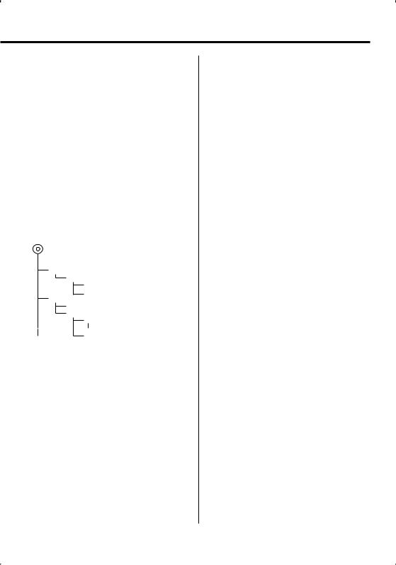
• Playing order of the Audio file
In the example of folder/file tree shown below, the files are played in the order from to .
CD ( ) |
: Folderer |
|
|
|
: Audiofile |
|
|
|
|
|
|
An online manual about audio files is put on the site, www.kenwood.com/audiofile/. On this online
manual, detailed information and notes which are not written in this manual are provided. Make sure to read through the online manual as well.
⁄
•In this manual, the word "USB device" is used for flash memories and digital audio players which have USB terminals.
•The word "iPod" appearing in this manual indicates the iPod connected with the KCA-iP200 (optional accessory). The iPod connected with the KCA-iP200 can be controlled from this unit. iPods that can be connected with the KCA-iP200 are the iPod nano and the iPod with video. When an iPod
is connected using a commercially available USB cable, it is handled as a mass-storage-class device.
•For the supported formats and types of USB device, refer to www.kenwood.com/usb/.
About USB device
•Install the USB device in the place where it will not prevent you from driving your vehicle properly.
•You cannot connect a USB device via a USB hub.
•Take backups of the audio files used with this unit. The files can be erased depending on the operating conditions of the USB device.
We shall have no compensation for any damage arising out of erasure of the stored data.
•No USB device comes with this unit. You need to purchase a commercially available USB device.
•For how to play the audio files recorded in a USB device, see <CD/USB device/Audio file/External disc control features> (page 23).
•When connecting the USB device, usage of the CAU1EX (option) is recommended.
Normal playback is not guaranteed when a cable other than the USB compatible cable is used. Connecting a cable whose total length is longer than 5 m can result in abnormal playback.
About Satellite Radio tuner
This unit supports Satellite Radio tuners which are released by SIRIUS and XM.
Refer to the instruction manual of Satellite radio tuner.
About Bluetooth Hands free control
Refer to the instruction manual of the Bluetooth Hands Free Box KCA-BT100 (optional accessory).
About Menu operation
For how to operate Menu, refer to <Menu System> in this instruction manual. For the items to be set up, refer to the instruction of Hands Free Box.
About display of Cell-Phone Status
Cell-Phone Status is displayed in the status display of this unit. For the information about the displayed
English | 5
Notes
Handling CDs
•Do not touch the recording surface of the CD.
•Do not stick tape etc. on the CD, or use a CD with tape stuck on it.
•Do not use disc type accessories.
•Clean from the center of the disc and move outward.
•When removing CDs from this unit, pull them out horizontally.
•If the CD center hole or outside rim has burrs, use the CD only after removing the burrs with a ballpoint pen etc.
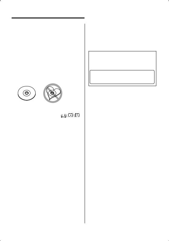
CDs that cannot be used
• CDs that are not round cannot be used.
• CDs with coloring on the recording surface or CDs that are dirty cannot be used.
• This unit can only play the CDs with


 . This unit may not correctly play discs which do not
have the mark.
•You cannot play a CD-R or CD-RW that has not been finalized. (For the finalization process refer to your CD-R/CD-RW writing software, and your CD-R/CD- RW recorder instruction manual.)
6 | English
2CAUTION
Use of controls or adjustments or performance of procedures other than those specified herein may result in hazardous radiation exposure.
In compliance with Federal Regulations, following are reproductions of labels on, or inside the product relating to laser product safety.
Kenwood Corporation 2967-3, ISHIKAWA-MACHI, HACHIOJI-SHI
TOKYO, JAPAN
KENWOOD CORP. CERTIFIES THIS EQUIPMENT CONFORMS TO DHHS REGULATIONS N0.21 CFR 1040. 10, CHAPTER 1, SUBCHAPTER J.
Location : Bottom Panel
FCC WARNING
This equipment may generate or use radio frequency energy. Changes or modifications to this equipment may cause harmful interference unless the modifications are expressly approved in the instruction manual. The user could lose the authority to operate this equipment if an unauthorized change or modification is made.
NOTE
This equipment has been tested and found to comply with the limits for a Class B digital device, pursuant to Part 15 of the FCC Rules. These limits are designed to provide reasonable protection against harmful interference in a residential installation. This equipment may cause harmful interference to radio communications, if it is not installed and used in accordance with the instructions. However, there
is no guarantee that interference will not occur in a particular installation. If this equipment does cause harmful interference to radio or television reception, which can be determined by turning the equipment off and on, the user is encouraged to try to correct the interference by one or more of the following measures:
•Reorient or relocate the receiving antenna.
•Increase the separation between the equipment and receiver.
•Connect the equipment into an outlet on a circuit different from that to which the receiver is connected.
•Consult the dealer or an experienced radio/TV technician for help.

General features
ATT VOL |
Release button |
FNC |
SRC Control knob |
ATT indicator
Function icon
Power
Turning ON the Power
Press the [SRC] button.
Turning OFF the Power
Press the [SRC] button for at least 1 second.
Selecting the Source
There are two types of source selection methods depending on the setting.
SRC Select mode 1:
1 Press the [SRC] button.
2Turn the Control knob or push it towards left or right.
3 Press the Control knob.
SRC Select mode 2:
Press the [SRC] button.
Source required |
Display |
Satellite radio (Optional accessory) |
"SAT" |
Tuner or HD Radio (Optional accessory) |
"TUNER" or "HD Radio" |
USB device (iPod)* |
"USB" ("iPod") |
CD |
"Compact Disc" |
External disc (Optional accessory) |
"CD Changer" |
Auxiliary input* |
"AUX" |
Auxiliary input (Optional accessory) |
"AUX EXT" |
Standby (Illumination only mode) |
"STANDBY" |
⁄
•* Function of KDC-X791/MP735U.
•When connection of the iPod is recognized, the source display changes from "USB" to "iPod".
•Switch between SRC Select mode 1 and 2 in <Source Select Mode> (page 34).
•USB (iPod) source is recognized as CD source on the connected unit.
English | 7

General features
Volume
Increasing Volume
Turn the [VOL] knob clockwise.
Decreasing Volume
Turn the [VOL] knob counterclockwise.
Attenuator
Turning the volume down quickly.
Press the [ATT] button.
Each time you press the button, the Attenuator turns ON and OFF.
When the Attenuator is ON, the "ATT" indicator blinks.
Audio Control
1Select the source to adjust
Press the [SRC] button.
Refer to <Selecting the Source> (page 7).
2Enter Audio Control mode
Press the [VOL] knob.
3Select the Basic Audio item to adjust
Press the [VOL] knob.
Each time you press the knob, the item to be adjusted alternates between the items shown in the table below.
4Adjust the Basic Audio item
Turn the [VOL] knob.
Adjustment Item |
Display |
Range |
Rear Volume |
"REAR VOLUME" |
0 — 35 |
Subwoofer level |
"SUB-W LEVEL" |
–15 — +15 |
System Q |
"USER"/"ROCK"/ |
User/Rock/ |
|
"POPS"/"EASY"/ |
Pops/Easy/ |
|
"TOP40"/"JAZZ"/ |
Top 40/Jazz/ |
|
"NATURAL" |
Natural |
Bass level* |
"BASS LEVEL" |
–8 — +8 |
Middle level* |
"MIDDLE LEVEL" |
–8 — +8 |
Treble level* |
"TREBLE LEVEL" |
–8 — +8 |
Balance |
"BALANCE" |
Left 15 — Right 15 |
Fader |
"FADER" |
Rear 15 — Front 15 |
EXIT AUDIO CONTROL MODE (VOLUME CONTROL MODE)
*You can adjust these items in detail. Refer to <Adjusting the detail of Audio Control>(Page8). (Function of KDCX791)
*Source tone memory: Puts the set up value in the memory per source. (Detail Audio item is included)
⁄ About System Q
•You can recall the best sound setting preset for different types of music.
•Change each setting value with the <Speaker Setting> (page 10). First, select the speaker type with the Speaker setting.
•"USER": The ranges selected lastly for Bass level, Middle level, and Treble level are recalled automatically.
5Exit Audio Control mode
Press any button.
Press a button other than the [VOL] knob and [ATT] button.
Function of KDC-X791
Adjusting the detail of Audio Control
Among the Basic Audio items, you can adjust the Bass level, Middle level, and Treble level in detail.
1Select the Basic Audio item
Select the desired item to be set in detail from followings;
•Bass level
•Middle level
•Treble level
For how to select Basic Audio items, see <Audio Control> (page 8).
2Enter Detail adjustment mode of Audio Control
Press the [VOL] knob for at least 1 second.
3Select the Detail Audio item to adjust
Press the [VOL] knob.
Each time you press the knob, the item to be adjusted alternates between the items shown in the table below.
4Adjust the Detail Audio item
Turn the [VOL] knob.
Bass level
Adjustment Item |
Display |
Range |
Bass Center Frequency |
"BASS FRQ" |
40/50/60/70/80/100/ |
|
|
120/150 Hz |
8 | English

Bass Q Factor |
"BASS Q FACTOR" |
1.00/1.25/1.50/2.00 |
Bass Extend |
"BASS EXT" |
OFF/ON |
Middle level |
|
|
|
|
|
Adjustment Item |
Display |
Range |
Middle Center Frequency |
"MIDDLE FRQ" |
0.5/1.0/1.5/2.0 kHz |
Middle Q Factor |
"MIDDLE Q FACTOR" 1.00/2.00 |
|
Treble level |
|
|
|
|
|
Adjustment Item |
Display |
Range |
Treble Center Frequency |
"TREBLE FRQ" |
10.0/12.5/15.0/17.5 kHz |
5Exit the Detail Audio Control mode
Press the [VOL] knob for at least 1 second.
⁄
•When you set the Bass Extend to ON, low frequency response is extended by 20%.
•You can exit the Audio Control mode at anytime by pressing any button except for [VOL] knob and [ATT] button.
Audio Setup
Setting the Sound system, such as Cross over Network.
1Select the source to adjust
Press the [SRC] button.
Refer to <Selecting the Source> (page 7).
2Enter Audio Setup mode
Press the [VOL] knob for at least 1 second.
3Select the Audio Setup item to adjust
Press the [VOL] knob.
Each time you press the knob, the item to be adjusted alternates between the items shown in the table below.
4Setup the Audio item
Turn the [VOL] knob.
Adjustment Item |
Display |
Range |
Front High Pass Filter |
"HPF-F Fc" |
Through/40*/60*/80/100/120/ |
|
|
150/180/220* Hz |
Rear High Pass Filter |
"HPF-R Fc" |
Through/40*/60*/80/100/120/ |
|
|
150/180/220* Hz |
Low Pass Filter |
"LPF-SW Fc" |
50*/60/80/100*/120/ |
|
|
Through Hz |
Subwoofer Phase |
"SW PHASE" |
Reverse (180°)/ Normal (0°) |
Volume offset |
"VOL-OFFSET" –8 — ±0 (AUX: -8— +8) |
|
Loudness |
"LOUD" |
OFF/ON |
Dual Zone System |
"2 ZONE" |
OFF/ON |
⁄
•* Function of KDC-X791/MP735U.
•Volume offset: Sets each source’s volume as a difference
from the basic volume.
• Loudness: Compensates for low and high tones during low volume. (Only the low tone is compensated for when the tuner is selected as a source.)
•Dual Zone System
Main source and sub source (Auxiliary input) output Front channel and Rear channel separately.
-Set up the channel of sub source by <Dual Zone System Setting> (page 36).
-Select Main source by [SRC] button.
-Adjust the volume of Front channel by [VOL] knob.
-Adjust the volume of Rear channel by <Audio Control> (page 8).
-The Audio Control has no effect on sub source.
•You can use the Dual Zone System with the Auxiliary input sources listed below.
-Internal auxiliary input. (KDC-X791/MP735U only)
-CA-C1AX/ CA-C2AX (optional accessory) connected to this unit directly. (KDC-MP635 only)
5Exit Audio Setup mode
Press the [VOL] knob for at least 1 second.
English | 9

General features
Speaker Setting
Fine-tuning so that the System Q value is optimal when setting the speaker type.
1Enter Standby
Press the [SRC] button.
Refer to <Selecting the Source> (page 7). Select the "STANDBY" display.
2Enter Speaker Setting mode
Press the [VOL] knob.
"SP SEL" is displayed.
3Select the Speaker type
Turn the [VOL] knob.
Each time you turn the knob, the setting alternates between the settings shown in the table below.
Speaker type |
Display |
|
OFF |
|
"OFF" |
For 5 |
& 4 in. speaker |
"5/4inch" |
For 6 |
& 6x9 in. speaker |
"6x9/6inch" |
For the OEM speaker |
"O.E.M." |
|
4Exit Speaker Setting mode
Press the [VOL] knob.
Subwoofer Output
Turning the Subwoofer output ON or OFF.
Push the Control knob toward down for at least 2 seconds.
Each time you push the knob, Subwoofer output switches ON and OFF.
When it is ON, "SUB WOOFER ON" is displayed.
TEL Mute
The audio system automatically mutes when a call comes in.
When a call comes in
"CALL" is displayed.
The audio system pauses.
Listening to the audio during a call
Press the [SRC] button.
The "CALL" display disappears and the audio system comes back ON.
10 | English
When the call ends
Hang up the phone.
The "CALL" display disappears and the audio system comes back ON.
⁄
•To use the TEL Mute feature, you need to hook up the MUTE wire to your telephone using a commercial telephone accessory. Refer to <Connecting Wires to Terminals> (page 44).
Function Control mode
To set up various functions of this unit, select treestructured function items.
1Enter Function Control mode
Press the [FNC] button.
2Select your desired setup item
Select a setup item using the Control knob.
Operation type |
Operation |
Movement between items |
Turn the Control knob. |
Selection of item |
Press the Control knob. |
Return to previous item |
Press the [FNC] button. |
Functions of items are as follows: |
|
Display |
Icon |
|
Function of setup item |
"Menu" |
"MENU" |
Allows you to set up the environment. Refer |
|
|
|
|
to <Menu system> (page 32). |
"Display Select" |
"DISP" |
|
Allows you to set up the display. Refer to |
|
|
|
page 11 to page 18. |
"Preset Memory" "P.MEM" |
Allows you to put stations in the memory. |
||
|
|
|
Refer to <Station Preset Memory> (page |
|
|
|
22). |
"File Scan" etc. |
"SCAN" |
|
Allows you to set how to play the CD and |
|
etc. |
|
audio file. Refer to <Play function of CD |
|
|
|
and Audio file> (page 26). |
"Return" |
" |
" |
Returns to the previous item. |
3Select an option for the selected item
Refer to the related pages for the operation of each option.
4Exit Function Control mode
Press the [FNC] button for at least 1 second.
Display Type Selection
Changing the display mode.
1Enter Display Type Selection mode
Using the Control knob, select "DISP" > "TYPE".
For the operation method, refer to <Function Control mode> (page 10).
2Select the display Type
Turn the Control knob.
Select from the following display types:
Display Mode |
Display |
|
|
|
|||
"TYPE SELECT [A]" |
|
|
|
|
|
|
|
|
|
|
|
|
2 |
|
|
|
1 |
|
|
|
|
|
|
|
|
|
|
|
|
|
|
"TYPE SELECT [B]" |
|
|
|
|
|
|
|
|
|
|
|
|
2 |
|
|
|
1 |
|
|
|
|
|
|
|
|
|
|
|
|
|
|
|
|
|
|
|
3 |
|
|
|
|
|
|
|
|
|
|
"TYPE SELECT [C]" |
|
|
|
|
|
|
|
|
|
|
|
|
2 |
|
|
|
|
|
|
|
|
|
|
|
|
0 |
|
4 |
|
|
|
|
|
|
|
|
|
|
|
|
|
0 |
|
5 |
|
|
|
|
|
|
|
|
|
|
|
|
|
0 |
|
6 |
|
|
|
"TYPE SELECT [D]"
2
!4
5
6
"TYPE SELECT [E]"
2
8 7
"TYPE SELECT [F]"
9
1 Graphic display part
2 Status display
3 Text display part
4 Upper text display part
5 Middle text display part
6 Lower text display part
7 Text display part
8 Graphic display part
9 G-Analyzer display part
0 Text icon display part ! Source icon display part
3Exit Display Type Selection mode
Press the Control knob.
⁄
•To change the information by the Display Type, refer to the page on the following table for the methods to alternate by the Display Type.
Display Type |
A |
B |
C |
D |
E |
F |
Graphic 1 |
12 |
12 |
— |
— |
— |
— |
Status 2 |
11 |
11 |
— |
— |
— |
— |
Text 3 |
— |
12 |
— |
— |
— |
— |
Upper 4 |
— |
— |
13 |
13 |
— |
— |
Middle 5 |
— |
— |
13 |
13 |
— |
— |
Lower 6 |
— |
— |
13 |
13 |
— |
— |
Text 7 |
— — — — 12 — |
|||||
G-Analyzer 9 |
— — — — — 15 |
|||||
Display Type A/ Display Type B
Status Setting
Determine whether the On and Off statuses of various functions are to be displayed on the Display Type A/B.
1Enter Status Setting mode
Using the Control knob, select "DISP" > "STATUS".
For the operation method, refer to <Function Control mode> (page 10).
2Select the Status display
Turn the Control knob.
3Exit Status Setting mode
Press the Control knob.
English | 11

General features
Display Type A/ Display Type B
Graphic Display Selection
Changing the graphic Display.
1Enter Graphic Display Selection mode
Using the Control knob, select "DISP" > "GRAPH".
For the operation method, refer to <Function Control mode> (page 10).
2Select the graphic display
Turn the Control knob or push it towards left or right.
Select from the following displays:
Graphic display |
Display |
Movie 1 – 2 |
|
Wallpaper 1 – 6 |
|
Wallpaper scan |
"SCAN" |
3Exit Graphic Display Selection mode
Press the Control knob.
⁄
•The setting of this function is available while "TYPE SELECT [A]"/ "TYPE SELECT [B]" is selected for the Display mode.
Text Display Selection
—Display Type B&E—
Selecting the text display.
1Enter Text Dispaly Selection mode
Using the Control knob, select "DISP" > "TEXT".
For the operation method, refer to <Function Control mode> (page 10).
2Select the text
Turn the Control knob or push it towards left or right.
See <The text display> (page 14).
Display Type B: Information of condition column "3" is displayed.
Display Type E: Information of condition column "7" is displayed.
3Exit Text Dispaly Selection mode
Press the Control knob.
⁄
•When LX-AMP is connected, the item setup by the Display mode of LX-AMP is displayed. (KDC-X791)
•When the music number exceeds 1000, only the last 3 digits of its number are displayed. (KDC-X791/MP735U)
•Album name cannot be displayed in WMA file. (KDCMP635)
•Music title, Artist name, and Album name cannot be displayed in WAV file. (KDC-X791/MP735U)
•When playing music from iPod or music edited by "Music Editor", the folder name display may show something different such as playlist or artist name depending on the music selection procedure. (KDC-X791/MP735U)
•In the Display Type B part, alternate information is displayed when display without information is selected.
•In the Display Type E part, no information is displayed when display without information is selected.
12 | English

Text Display Selection
— Display Type C&D—
Changing the text display.
1Enter Text Display Selection mode
Using the Control knob, select "DISP" > "TEXT".
For the operation method, refer to <Function Control mode> (page 10).
2Select the text display part
Push the Control knob towards up or down.
The cursor (‰) moves to the selected text display part.
Select the text
Turn the Control knob or push it towards left or right.
See <The text display> (page 14).
Upper text display part: Information of condition column "4" is displayed.
Middle text display part: Information of condition column "5" is displayed.
Lower text display part: Information of condition column "6" is displayed.
3Exit Text Display Selection mode
Press the Control knob.
⁄
•When LX-AMP is connected, the item setup by the Display mode of LX-AMP is displayed. (KDC-X791)
•When the music number exceeds 1000, only the last 3 digits of its number are displayed. (KDC-X791/MP735U)
•Album name cannot be displayed in WMA file. (KDCMP635)
•Music title, Artist name, and Album name cannot be displayed in WAV file. (KDC-X791/MP735U)
•When playing music from iPod or music edited by "Music Editor", the folder name display may show something different such as playlist or artist name depending on the music selection procedure. (KDC-X791/MP735U)
•Same information cannot be displayed in Upper text display part, Middle text display part and Lower text display part. However, the blank display is able to have multiple selections.
•In the upper text display part, alternate information is displayed when display without information is selected.
•In the middle text display part, the Kenwood logo is displayed if the contents of the information cannot be displayed. However, in the HD Radio source part, the display becomes blank.
•In the lower text display part, no information is displayed when display without information is selected.
English | 13

General features
The text display
In Tuner source
|
Information |
Display |
Condition |
|
Station name |
"SNPS" |
34 |
|
Frequency |
"Frequency" |
34 |
|
Clock |
"Clock" |
34567 |
|
Date |
"Date" |
34567 |
|
Blank |
"Blank" |
567 |
In CD & External disc source |
|
||
|
|
|
|
|
Information |
Display |
Condition |
|
Disc title |
"Disc Title" |
34567 |
|
Track title |
"Track Title" |
34567 |
|
Track number & Play time |
"P-Time" |
34 |
|
Disc name |
"DNPS" |
34567 |
|
Clock |
"Clock" |
34567 |
|
Date |
"Date" |
34567 |
|
Blank |
"Blank" |
567 |
In Audio file source |
|
|
|
|
|
|
|
|
Information |
Display |
Condition |
|
Music title & Artist name |
"Title/Artist" |
34567 |
|
Album name & Artist name |
"Album/Artist" |
34567 |
|
Folder name |
"Folder Name" |
34567 |
|
File name |
"File Name" |
34567 |
|
Play time & Music number |
"P-Time" |
34 |
|
Clock |
"Clock" |
34567 |
|
Date |
"Date" |
34567 |
|
Blank |
"Blank" |
567 |
In Standby |
|
|
|
|
|
|
|
|
Information |
Display |
Condition |
|
Standby |
"Source Name" |
34 |
|
Clock |
"Clock" |
34567 |
|
Date |
"Date" |
34567 |
|
Blank |
"Blank" |
567 |
In Auxiliary input source |
|
||
|
|
|
|
|
Information |
Display |
Condition |
|
Auxiliary input name |
"Source Name" |
34 |
|
Clock |
"Clock" |
34567 |
|
Date |
"Date" |
34567 |
|
Blank |
"Blank" |
567 |
In HD Radio source
|
Information |
Display |
Condition |
|
Station name |
"Station Name" |
34 |
|
Title |
"Title" |
34567 |
|
Frequency |
"Frequency" |
34 |
|
Clock |
"Clock" |
34567 |
|
Date |
"Date" |
34567 |
|
Blank |
"Blank" |
567 |
In Satellite radio source |
|
|
|
|
|
|
|
|
Information |
Display |
Condition |
|
Channel Name |
"Channel Name" |
34567 |
|
Music Title |
"Song Title" |
34567 |
|
Artist Name |
"Artist Name" |
34567 |
|
Composer name |
"Composer Name" |
34567 |
|
Category Name |
"Category Name" |
34567 |
|
Label Name |
"Label Name" |
34567 |
|
Comment |
"Comment" |
34567 |
|
Band & Channel Number |
"Channel Number" 34 |
|
|
Clock |
"Clock" |
34567 |
|
Date |
"Date" |
34567 |
|
Blank |
"Blank" |
567 |
Display Type B/ Display Type C/ Display Type D
Font Color Selection
Selecting the display font color.
1Enter Font Color Selection mode
Using the Control knob, select "DISP" > "COLOR".
For the operation method, refer to <Function Control mode> (page 10).
2Select the text display part (Display Type C/ Display Type D only)
Push the Control knob towards up or down.
The cursor (‰) moves to the selected text display part.
3Select the Font Color
Turn the Control knob or push it towards left or right.
4Exit Font Color Selection mode
Press the Control knob.
⁄
•When you selected the Display Type B display, select an easy viewable font color.
14 | English
Display Type F
G-Analyzer display Selection
Changing the G-Analyzer display.
⁄
•Before alternating G-Analyzer display, you are required to setup <G-Counter Level seting> (page 17), <G-Analyzer Calibration setup> (page 18), <G-Analyzer vehicle weight setup> (page 18) and <G-Analyzer vehicle class setup> (page 18).
1 Enter G-Analyzer display selection mode
Using the Control knob, select "DISP" > "GMENU".
For the operation method, refer to <Function Control mode> (page 10).
2Select the G-Analyzer display
Turn the Control knob.
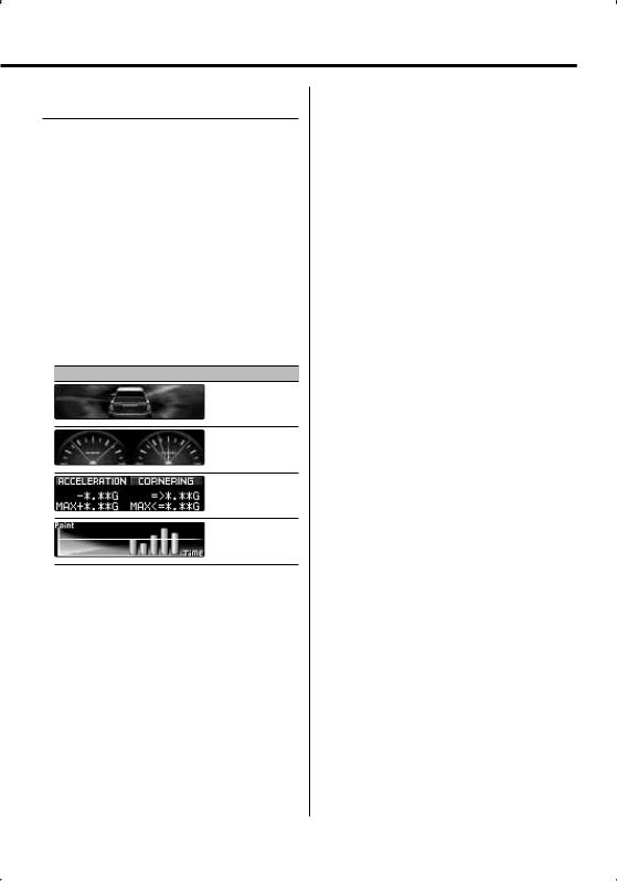
Select from the following displays.
G-Force Sensor display
G- Graphic display 1 – 2
G-Meter display (Graphic)
G-Meter display (Text)
G-Counter display
⁄
•G-Graphic display
Displays the condition of G in horizontal direction (e.g; when turning the curve) by the graphic.
•G-Meter display (Graphic)
Displays the maximum value of acceleration G, right direction G, and left direction G by the numerical value.
•G-Meter display (Text)
The maximum value of acceleration G, right direction G, and left direction G is displayed by the numerical value. The value of G is only the reference, so is different from the actual value.
•G-Counter display
Adds the point of the acceleration level. The point is determined after a lapse of 1 hr drive or at power off (ACC Off ), and then it will be displayed by the graph.
Furthermore, the G-Counter displays the average of the past data by the line. (The scale of graph is determined along with the largest point among the past 10 data.)
•The value of G-Meter display and G-Counter display can be reset by <G-Analyzer Reset> (page 17).
3Exit G-Analyzer display selection mode
Press the Control knob.
English | 15

General features
Display Type F
G-Analyzer Stop Watch
The control of stop watch can be started by G- Analyzer function.
¤
• Do not use G-Analyzer stop watch on the Public roads.
1 Enter G-Analyzer Stop Watch mode
Using the Control knob, select "DISP" > "GMA" > "STOP.W".
For the operation method, refer to <Function Control mode> (page 10).
"STOP WATCH" is displayed.
2Make the counter ready
Press the Control knob.
"Ready" is displayed.
3Start Count
When G in the vertical direction is detected during the travel, the count automatically starts. "Running" is displayed.
⁄
•You can also start the counter by pressing the Control knob.
4Stop Count
Press the Control knob.
"Stop" is displayed.
⁄
•The control will start again when you accelerate or press the Control knob.
Do the operation after step2.
When you Reset the Count (While "Stop" is displayed)
Press the Control knob for at least 1 second.
⁄
• You can reset of count when the count is stopped.
5Exit G-Analyzer Stop Watch mode
Press the [FNC] button.
⁄
•When Power off (ex; ACC OFF) while counting, the value of 1 second or less will be "00".
16 | English
Display Type F
G-Analyzer Horsepower Analysis
This measures the horsepower and displays graph and max power. It automatically saves the highest record.
¤
•Do not use G-Analyzer Horsepower Analysis on the Public roads.
•Do not use this product in any way that prevents you from driving safely.
•Follow all driving laws and use common sense when using this product.
⁄
•Before alternating G-Analyzer Horsepower Analysis, you are required to setup <G-Analyzer vehicle weight setup> (page 18) and <G-Analyzer vehicle class setup> (page 18).
1 Enter G-Analyzer Horsepower Analysis mode
Using the Control knob, select "DISP" > "GMA" > "HP".
For the operation method, refer to <Function Control mode> (page 10).
"HORSEPOWER" is displayed.
Previous max power and record are displayed.
2Begin measurement
Press the Control knob.
"Ready" is displayed.
3Start the car
"Measure" is displayed.
After 15 seconds of measurement, the result is displayed.
Display the result
The graph shows the variation in horsepower between 0.1 to 15.0 seconds. The maximum power is displayed in red and the markings provided at intervals of 5 seconds are displayed in blue.
¤
•Pressing the Control knob also begins the measurement. To prevent danger, push the control knob before starting the car.
4To display the maximum power in the section
Push the Control knob towards right or left.
Each time you push the Control knob, the maximum power in the section is displayed.
5Exit G-Analyzer Horsepower Analysis mode
Press the [FNC] button.
 Loading...