


Operation, Safety, Maintenance and service Manual
Original Instructions - Keep this manual with the machine at all times.
Boom Lift Models
X20JPLUS
X20JPR002
April, 2013

JLG LIFT
FOREWORD
For:
•Accident Reporting
•Product Safety Publications
•Current Owner Updates
•Questions Regarding Product Safety
•Standards and Regulations Compliance Information
•Questions Regarding Special Product Applications
•Questions Regarding Product Modifications
Contact:
Product Safety and Reliability Department
JLG Industries, Inc.
13224 Fountainhead Plaza
Hagerstown, MD 21742
or Your Local JLG Office
(See addresses on manual cover)
In USA:
Toll Free: 877 JLG SAFE (877 554 7233)
Outside USA:
Phone: 240 420 2661
Fax: 301 745 3713
E mail: ProductSafety@JLG.com
X20JPR002

JLG LIFT
FOREWORD
REVISION LOG
Rev. |
Manual code |
Date |
Original Issue |
X20JPR002 |
April, 2013 |
|
|
|
|
|
|
|
|
|
|
|
|
|
|
|
|
|
|
|
|
|
|
|
|
|
|
|
|
|
|
|
|
|
X20JPR002

BOOM LIFT MODELS X20JPLUS
JLG
TABLE OF CONTENTS
CHAPTER |
1 |
PRESENTATION .................................................................................... |
Page 08 |
CHAPTER |
2 |
TECHNICAL INFORMATION ........................................................... |
Page 09 |
|
2.1 |
Description of the machine ................................................................... |
Page 09 |
|
2.1.1 |
Control position ..................................................................................... |
Page 09 |
|
2.1.2 |
Machine identification plate ................................................................. |
Page 12 |
|
2.1.3 |
Overall dimensions of the machine ..................................................... |
Page 13 |
|
2.1.4 |
Technical specifications ......................................................................... |
Page 14 |
|
2.1.4.1 |
Petrol engine technical specifications .................................................. |
Page 15 |
|
2.1.4.2 |
Diesel engine technical specifications.................................................. |
Page 15 |
|
2.1.4.3 |
Hydraulic system technical specifications .......................................... |
Page 15 |
|
2.1.4.4 |
Electrical system technical specifications Thermic ............................ |
Page 16 |
|
2.1.4.5 |
Electrical system technical specifications Lithium ............................ |
Page 16 |
|
2.1.5 |
Terminology ............................................................................................ |
Page 17 |
|
2.2 |
General safety standards ....................................................................... |
Page 18 |
|
2.3 |
Safety warnings....................................................................................... |
Page 22 |
|
2.3.1 |
Generalities.............................................................................................. |
Page 22 |
|
2.3.2 |
Noise and vibrations .............................................................................. |
Page 22 |
|
2.3.3 |
Pictograms positioned on the machine ............................................... |
Page 23 |
CHAPTER |
3 |
SAFETY DEVICES .................................................................................. |
Page 38 |
|
3.1 |
Battery cutout switch ............................................................................. |
Page 39 |
|
3.2 |
Distributor pressure relief valves ......................................................... |
Page 39 |
|
3.3 |
Cylinder stop valves............................................................................... |
Page 40 |
|
3.4 |
Alignment photocell on the aerial part of the structure and the |
|
|
|
base of the machine ............................................................................... |
Page 40 |
|
3.5 |
Stabiliser position microswitches......................................................... |
Page 41 |
|
3.6 |
Jib position microswitch ........................................................................ |
Page 41 |
|
3.7 |
Basket load sensor .................................................................................. |
Page 42 |
|
3.8 |
Control protection .................................................................................. |
Page 43 |
|
3.9 |
Spirit level ................................................................................................ |
Page 43 |
|
3.10 |
Pin locking bolts and nuts ..................................................................... |
Page 44 |
|
3.11 |
Safety device electronic control board................................................. |
Page 44 |
CHAPTER |
4 |
INSTRUMENTS AND CONTROLS..................................................... |
Page 46 |
|
4.1 |
Remote control ........................................................................................ |
Page 46 |
|
4.1.1 |
Display ..................................................................................................... |
Page 47 |
|
4.1.1.1 |
Display main screen ............................................................................... |
Page 47 |
|
4.1.2 |
Joysticks ................................................................................................... |
Page 51 |
|
4.1.3 |
Push buttons............................................................................................ |
Page 53 |
|
4.2 |
Footswitch ............................................................................................... |
Page 57 |
|
4.3 |
Control positions ................................................................................... |
Page 57 |
CHAPTER |
5 |
EMERGENCY DEVICES ....................................................................... |
Page 58 |
|
5.1 |
Emergency stop button.......................................................................... |
Page 58 |
|
5.2 |
Hand pump ............................................................................................. |
Page 59 |
|
5.3 |
Solenoid valves for emergency descent............................................... |
Page 59 |
|
5.4 |
Safety device bypass key ....................................................................... |
Page 60 |
|
5.5 |
Emergency position controls................................................................. |
Page 61 |
CHAPTER |
6 |
USING THE MACHINE........................................................................ |
Page 66 |
|
6.1 |
Safety standards to adopt before using the platform................................ |
Page 66 |
|
6.1.1 |
Risk of electrocution............................................................................... |
Page 66 |
|
6.1.2 |
Danger due to atmospheric conditions .............................................. |
Page 67 |
|
6.1.3 |
Danger due to the work area ................................................................ |
Page 67 |
|
6.2 |
Procedures for correct use ..................................................................... |
Page 68 |
|
6.2.1 |
Summary table of operator safety standards...................................... |
Page 68 |
|
6.3 |
Working area ........................................................................................... |
Page 70 |
|
6.4 |
Using the elevating work platform (MEWP) ..................................... |
Page 71 |
X20JPR0020413 |
1 |

BOOM LIFT MODELS X20JPLUS
JLG
|
6.4.1 |
Preliminary checks before starting work ........................................... |
Page 72 |
|
6.4.2 |
Starting the petrol/diesel engine ......................................................... |
Page 73 |
|
6.4.3 |
Starting the electric motor ................................................................... |
Page 74 |
|
6.4.4 |
Stopping the engine/motor ................................................................... |
Page 76 |
|
6.4.5 |
Stopping the motor lithium version .................................................... |
Page 76 |
|
6.4.6 |
Travel ........................................................................................................ |
Page 77 |
|
6.4.7 |
Jib arm movement for travel ................................................................. |
Page 80 |
|
6.4.8 |
Parking the machine on a slope or on uneven ground .................... |
Page 82 |
|
6.4.9 |
Stabilising and levelling the machine .................................................. |
Page 82 |
|
6.4.10 |
Automatic lowering and raising of the stabilisers ............................ |
Page 86 |
|
6.4.11 |
Track gauge extension............................................................................ |
Page 88 |
|
6.4.12 |
Moving the basket ................................................................................. |
Page 89 |
|
6.4.13 |
Manually levelling the basket .............................................................. |
Page 93 |
|
6.5 |
Emergency operations on the aerial part ........................................... |
Page 94 |
|
6.5.1 |
Emergency descent controlled from the basket ................................. |
Page 94 |
|
6.5.2 |
Operating the machine from the emergency control position |
|
|
|
on the ground if the operator is taken ill ............................................ |
Page 95 |
|
6.5.3 |
Emergency descent in the case where the stabilisers are |
|
|
|
accidentally retracted ............................................................................. |
Page 96 |
|
6.5.4 |
Emergency descent controlled from the ground using the hand |
|
|
|
pump in the event of faults on all energy supply systems ............. |
Page 98 |
|
6.5.5 |
Emergency operations on the carriage: moving the platform |
|
|
|
stabilisers using the hand pump to allow the machine |
|
|
|
to be transported..................................................................................... |
Page 100 |
|
6.5.6 |
Emergency operation of the undercarriage in the event of |
|
|
|
movements of the aerial part ................................................................ |
Page 101 |
|
6.6 |
Electrical disconnection of the remote control ................................... |
Page 103 |
|
6.7 |
Recharging the battery .......................................................................... |
Page 104 |
|
6.8 |
Main intended uses of the platform..................................................... |
Page 108 |
|
6.8.1 |
Systems..................................................................................................... |
Page 108 |
|
6.8.2 |
Closed environments ............................................................................. |
Page 108 |
|
6.8.3 |
Pruning..................................................................................................... |
Page 108 |
|
6.8.4 |
Repair and maintenance of roofing and gutters ................................ |
Page 109 |
|
6.8.5 |
Painting, sand blasting and plastering................................................ |
Page 109 |
|
6.8.6 |
Use in marine environments................................................................. |
Page 109 |
CHAPTER |
7 |
MAINTENANCE.................................................................................... |
Page 110 |
|
7.1 |
Safety instructions for greasing and lubrication ................................ |
Page 110 |
|
7.2 |
Table of recommended lubricants ........................................................ |
Page 110 |
|
7.3 |
Greasing points ....................................................................................... |
Page 112 |
|
7.4 |
Greasing the telescopic arm .................................................................. |
Page 113 |
|
7.5 |
Safety instructions for maintenance operations................................. |
Page 113 |
|
7.6 |
Operating the machine from the second control position on the |
|
|
|
ground using the optional second remote control during |
|
|
|
maintenance ............................................................................................ |
Page 114 |
|
7.7 |
Periodic maintenance intervals............................................................. |
Page 115 |
|
7.8 |
Electric motor .......................................................................................... |
Page 117 |
|
7.8.1 |
Electric motor maintenance .................................................................. |
Page 117 |
|
7.9 |
Inspection and maintenance ................................................................. |
Page 118 |
|
7.10 |
General periodic checks......................................................................... |
Page 120 |
|
7.11 |
Maintenance on the rubber tracks ....................................................... |
Page 121 |
|
7.11.1 |
Checking the track tension .................................................................... |
Page 121 |
|
7.11.2 |
Loosening/tightening the tracks ........................................................... |
Page 121 |
|
7.11.3 |
Checking the rubber tracks ................................................................... |
Page 122 |
|
7.11.4 |
Replacing the rubber tracks .................................................................. |
Page 124 |
|
7.12 |
Checking tightness of nuts and bolts................................................... |
Page 125 |
|
7.13 |
Checking the hydraulic oil level........................................................... |
Page 129 |
|
7.13.1 |
Hydraulic oil............................................................................................ |
Page 129 |
|
7.14 |
Checking for leaks in the hydraulic system........................................ |
Page 129 |
|
7.15 |
Checking the condition of the filter cartridge .................................... |
Page 130 |
2 |
X20JPR0020413 |

BOOM LIFT MODELS X20JPLUS
JLG
|
7.16 |
Checking that all the plates are present on the machine |
|
|
|
and intact ................................................................................................. |
Page 130 |
|
7.17 |
Checking the operating pressure of the hydraulic system ............... |
Page 131 |
|
7.18 |
Checking tightness of the fastening screws on the pin retainers |
|
|
|
and the locknuts...................................................................................... |
Page 131 |
|
7.19 |
Replacing /checking extension ropes................................................... |
Page 132 |
|
7.19.1 |
Checking wear and deformation of ropes and pulleys..................... |
Page 132 |
|
7.20 |
Three monthly inspection ..................................................................... |
Page 133 |
|
7.21 |
Five yearly inspection ............................................................................ |
Page 135 |
|
7.22 |
Checking wear on the telescopic arm slides ....................................... |
Page 136 |
|
7.23 |
Checking extension pulley wear .......................................................... |
Page 136 |
|
7.24 |
Checking tightness of the turntable bolts............................................ |
Page 136 |
|
7.25 |
Battery: checks and maintenance thermic version .......................... |
Page 136 |
|
7.25.1 |
Checking the electrolyte level thermic version ................................ |
Page 137 |
|
7.25.2 |
Recharging the battery thermic version............................................ |
Page 137 |
|
7.25.3 |
Replacing the battery thermic version .............................................. |
Page 138 |
|
7.25.4 |
Battery disposal....................................................................................... |
Page 138 |
|
7.26 |
Battery pack operating specifications.................................................. |
Page 139 |
|
7.26.1 |
Components and diagrams ................................................................... |
Page 140 |
|
7.26.2 |
Personal protective equipment ............................................................. |
Page 142 |
|
7.26.3 |
Handling in dangerous conditions ...................................................... |
Page 142 |
|
7.26.3.1 |
Procedure for handling hot cells .......................................................... |
Page 143 |
|
7.26.3.2 |
Procedure for handling vented cells .................................................... |
Page 144 |
|
7.26.3.3 |
Procedure for exploded cells................................................................. |
Page 145 |
|
7.26.3.4 |
Lithium battery fire ................................................................................ |
Page 147 |
|
7.27 |
Servicing the engine ............................................................................... |
Page 149 |
CHAPTER |
8 |
SAFETY STANDARDS FOR TRANSPORT ........................................ |
Page 150 |
|
8.1 |
Removing the basket.............................................................................. |
Page 150 |
|
8.2 |
Loading and unloading the machine on transport vehicles |
|
|
|
using ramps ............................................................................................. |
Page 151 |
|
8.3 |
Lifting the machine................................................................................. |
Page 152 |
|
8.3.1 |
Lifting the machine using a forklift .................................................... |
Page 153 |
|
8.3.2 |
Lifting the machine using ropes or chains ........................................ |
Page 154 |
|
8.3.3 |
What to use to attach the platform....................................................... |
Page 155 |
|
8.4 |
Transporting the machine...................................................................... |
Page 156 |
CHAPTER |
9 |
SERVICE MENU ON THE REMOTE CONTROL ............................. |
Page 157 |
|
9.1 |
Input menu .............................................................................................. |
Page 157 |
|
9.2 |
Error menu............................................................................................... |
Page 159 |
|
9.3 |
Operating hours menu........................................................................... |
Page 159 |
|
9.4 |
Settings menu.......................................................................................... |
Page 159 |
|
9.5 |
Joystick menu .......................................................................................... |
Page 159 |
CHAPTER |
10 |
TROUBLESHOOTING........................................................................... |
Page 160 |
CHAPTER |
11 |
CHECKS TO BE COMPLETED ON THE MACHINE |
|
|
|
FOLLOWING REPAIRS......................................................................... |
Page 168 |
|
11.1 |
Checking correct operation of the controls......................................... |
Page 168 |
|
11.2 |
Checking operation of the safety devices............................................ |
Page 168 |
CHAPTER |
12 |
HYDRAULIC SYSTEM .......................................................................... |
Page 169 |
|
12.1 |
Hydraulic system diagram thermic version ....................................... |
Page 169 |
|
12.1.1 |
Key to the hydraulic system diagram thermic version ..................... |
Page 170 |
CHAPTER |
13 |
WIRING DIAGRAM .............................................................................. |
Page 171 |
X20JPR0020413 |
3 |
BOOM LIFT MODELS X20JPLUS
JLG
PREFACE
The aim of this manual is to provide the user with the necessary instructions and essential operating procedures to ensure correct and safe use of the machine for its intended purpo ses, as well as to prevent serious injury to the operator and other persons.
IMPORTANT
IT IS MANDATORY TO KEEP TO ALL THE INSTRUCTIONS GIVEN IN THIS MANUAL. THIS MANUAL MUST BE CAREFULLY READ AND UNDERSTOOD BEFORE OPERA TING THE MACHINE.
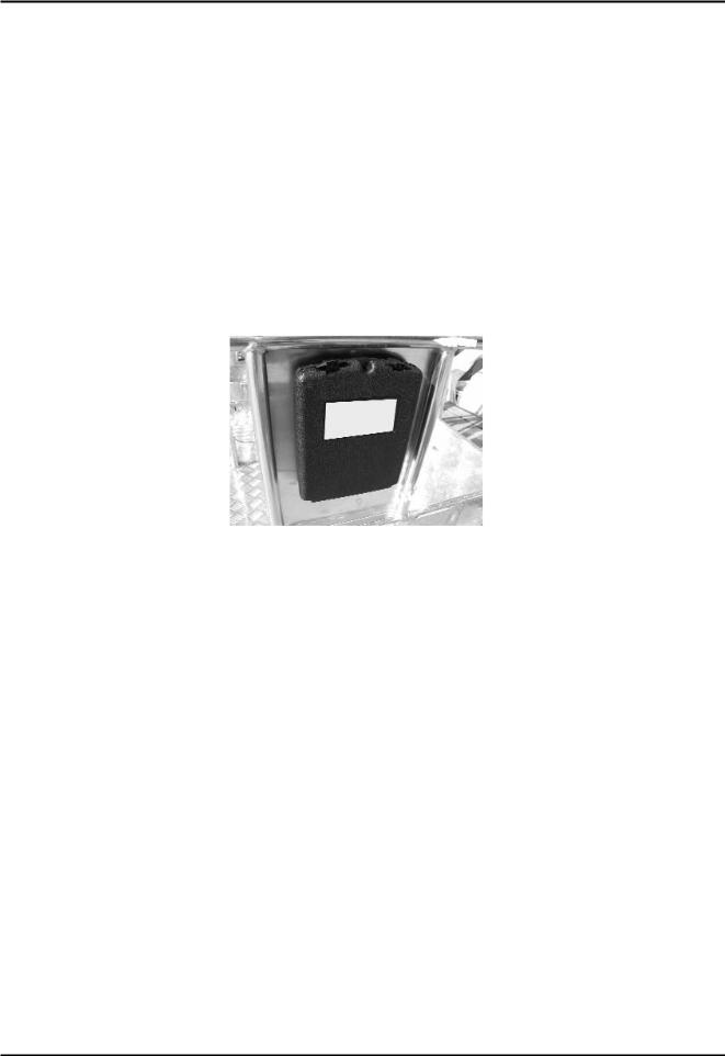
As this manual is an essential work tool, it must be kept with the machine at all times, in the special compartment, so as to be available for clarification whenever required.
As the manufacturer cannot control the conditions of the machine and the operations this is used for, THE USER IS RESPONSIBLE for ensuring compliance with the safety procedures described in this manual.
Every machine supplied is thoroughly adjusted and tested before being delivered. The ope rator does not need to perform any adjustments before using the machine.
Every alteration and/or modification of the features of the original machine design without previous written authorisation from the Constructor are PROHIBITED and THE RESPONSI BILITY FOR THESE ACTIONS FALLS ON THE OPERATOR.
THE EMPLOYER MUST MAKE SURE THAT THE OPERATOR HAS THE REQUISITES NECESSARY TO OPERATE THE MACHINE CORRECTLY AND THAT SUCH OPERA TOR HAS CAREFULLY EXAMINED AND UNDERSTOOD THE INFORMATION GIVEN IN THIS USER AND OPERATION MANUAL, RECEIVING SUITABLE TRAI NING REGARDING USE OF THE MACHINE IN STANDARD AND EMERGENCY CONDITIONS.
THE EMPLOYER MUST ALSO TRAIN OPERATORS REGARDING ANY NATIONAL STANDARDS THAT ARE IN ADDITION TO THE INSTRUCTIONS CONTAINED IN THIS DOCUMENT.
If the manual is damaged or lost, a copy must be requested directly from JLG.
4 |
X20JPR0020413 |

BOOM LIFT MODELS X20JPLUS
JLG
Note: All of the photos and drawings in this manual have been added to simplify com prehension by the reader. Your machine may differ from the photos and drawings provi ded.
NORMATIVE REFERENCES
The machine has been designed, built and inspected according to that prescribed in the EN280 prA2:2009 harmonised standard, which supplies the presumption of conformity with the Essential Safety Requisites of the 2006/42/CE Machinery Directive even if a type C Volun tary Technical Standard.
According to that stated in EN280 prA2, the JLG platform is classified in GROUP B, as the vertical projection of the centre of gravity of the load can be outside of the tilting lines and in TYPE 1 as traversing is only allowed with the platform at rest.
The stability tests of the machine have been made in accordance with what described in paragraph 6.1.4.2 of the EN280 with load test calculated in conformity with 5.2.4 and have been successful.
In addition what prescribed in this manual it is necessary to apply the technical require ments of the following national/international safety standards:
UNI ISO 18893
ISO 16368
ISO 18878
With the exception of stricter local or national regulations in the working area of the MEWP.
WARRANTY
On purchasing a JLG platform, a warranty and inspection certificate is issued that clearly indicates the warranty terms and where any interventions on the machine must be reported.
LIABILITY
The Constructor is exonerated from any liability and obligation for any injury/damage cau sed to persons/objects due to any of the reasons listed below:
•Failure to comply with the instructions indicated in this USE AND MAINTENANCE MANUAL regarding running, use and maintenance of the machine;
•Violent or sudden actions or incorrect manoeuvres when using or servicing the machine;
•Modifications made to the structure or machine components without previous authori sation from the Constructor and/or without the use of suitable equipment;
•Strange events with respect to normal and correct use of the machine, described in this USE AND MAINTENANCE MANUAL.
•Use of non original spare parts not authorised by the manufacturer.
X20JPR0020413 |
5 |

BOOM LIFT MODELS X20JPLUS
JLG
EC DECLARATION OF CONFORMITY
|
EC DECLARATION OF |
|
|
CONFORMITY |
|
Manufacturer |
JLG Industries Inc |
|
Address |
1 JLG Drive |
|
|
McConnellsburg |
|
|
PA17233 |
|
|
USA |
|
Technical File: |
JLG Industries Inc |
|
|
JLG Technology & Development Centre |
|
|
Bruntingthorpe Aerodrome & Proving Ground |
|
|
Lutterworth, Leicestershire |
|
|
LE17 5QS |
|
|
United Kingdom. |
|
Authorised contact |
Alan S. McIntyre |
Position: Manager, Engineering |
|
|
Support - Europe |
Machine Type: |
Mobile Elevating Work Platform |
|
Model Type: |
... |
|
Serial Number: ... |
|
|
Notified Body: |
ECO Certificazioni S.p.A |
|
EC Number: |
0714 |
|
Address |
Via Mengollna |
|
|
33 - 48108 |
|
|
Faenza |
|
|
Italy |
|
Certificate Number: |
To Be Advised |
|
Reference Standards: |
EN12100-1 & 2:2003 + A1:2009 |
|
|
EN280:2001 + A2:2009 |
|
JLG Industries hereby declare that the above mentioned machine conforms with the requirements of:
2006/42/EC |
Machinery |
2004/108/EC |
EMC Directive |
2000/14/EC |
Outdoor Noise |
Signed: |
|
Date: |
... |
Name: |
Alan S. McIntyre |
Position: |
Manager,Engineering Support- |
|
|
|
Europe |
|
|
Place: |
Bruntingthorpe, UK |
Remark:
Any modification to the above described machine violates the validity of this declaration. This declaration conforms with the requirements of annex II-A of the council directive 2006/42/EC
Machine manufactured for JLG Industries Inc. by HINOWA S.p.a via Fontana 37054 NOGARA VR Italy
6 |
X20JPR0020413 |
BOOM LIFT MODELS X20JPLUS
JLG
EC DECLARATION OF
CONFORMITY
Manufacturer |
JLG Industries Inc |
|
|
|
Address |
1 JLG Drive |
|
|
|
|
McConnellsburg |
|
|
|
|
PA17233 |
|
|
|
|
USA |
|
|
|
Machine Type: |
Mobile Elevating Work Platform |
|
||
Model Type: |
... |
|
|
|
Serial Number: |
... |
|
|
|
Document Control: |
HINOWA S.p.A |
Technical File: |
JLG Industries Inc |
|
|
Via Fontana - 37054 |
|
JLG Technology & |
|
|
Nogara |
|
|
Development Centre |
|
Italy |
|
|
Bruntingthorpe |
|
|
|
|
Aerodrome & Proving |
|
|
|
|
Ground |
|
|
|
|
Lutterworth, |
|
|
|
|
Leicestershire |
|
|
|
|
LE17 5QS |
|
|
|
|
United Kingdom. |
Measured |
|
|
|
|
Lwa |
dB(A)... |
|
|
|
Guaranteed |
|
|
|
|
Lwa |
dB(A)... |
|
|
|
Engine Power: |
kW |
... |
|
|
Lwa |
= (Sound Power Level) |
|
||
Applicable Procedure: |
EN ISO 3744:1995 |
|
|
|
Applicable Directive: |
2000/14/EC Annex V Internal Control of Production. |
|||
We hereby declare that the above mentioned machine conforms with the requirements of the "Noise Emission in the Environment by Equipment for Use Outdoors" Directive 2000/14/EC & 2005/88/EC
Remark:
This declaration conforms with the requirements of Annex II of the council directive 2000/14/EC
Any modification to the above described machine violates the validity of this declaration. Machine manufactured for JLG Industries Inc. by HINOWA S.p.a via Fontana 37054 NOGARA VR Italy
X20JPR0020413 |
7 |

BOOM LIFT MODELS X20JPLUS
JLG
1. PRESENTATION
This manual describes the warning signs used to draw the reader’s attention to several parti cularly important warnings.
The safety warnings are divided into two main types, which are identified and described below.
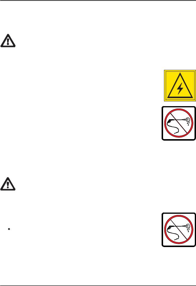
DANGER
This symbol accompanied by the word DANGER indicates that the situation described, if not prevented, can lead to serious injury or death of the persons involved (operator, ground staff, staff present in proximity to the platform, main tenance technicians etc.).
WARNING
This symbol accompanied by the word WARNING indicates that the situation described represents a potential risk for the structure of the machine.
Dangerous situations may be determined by this condition (including injury or death) for the persons involved.
8 |
X20JPR0020413 |
BOOM LIFT MODELS X20JPLUS
JLG
2. TECHNICAL INFORMATION
2.1. DESCRIPTION OF THE MACHINE
The JLG machine is a self propelled hydraulic lifting device, equipped with a rotating work basket positioned at the top of an extendable articulated structure, which also rotates. The JLG lifting device is destined for the POSITIONING OF PERSONS AND THEIR EQUIP MENT AND MATERIALS IN HIGH POSITIONS WITH RESPECT TO GROUND LEVEL.
2.1.1 CONTROL POSITION
CONTROL POSITION IN THE BASKET
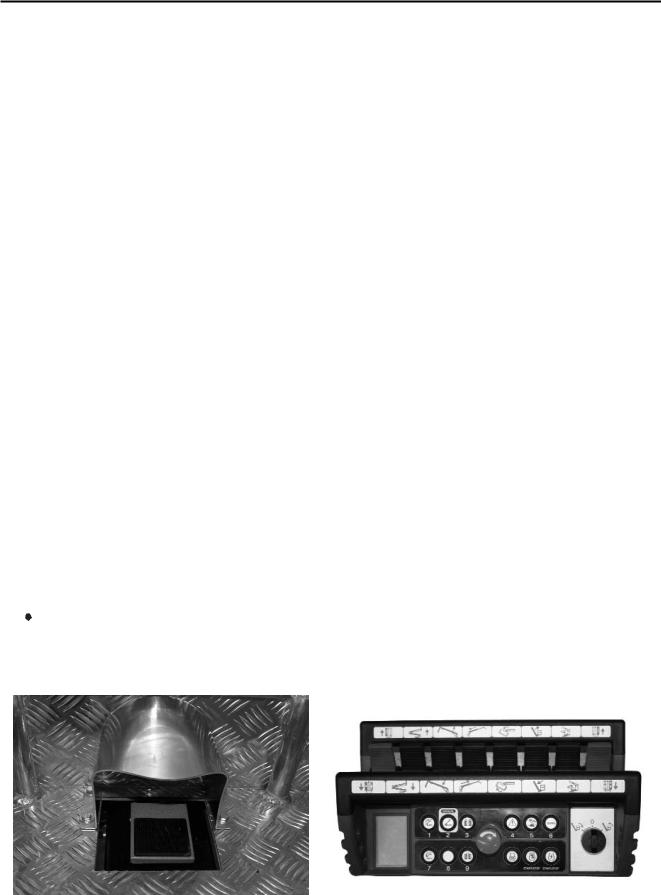
The JLG aerial work platform has been designed to be controlled by the operator in the basket using a remote control, where all of the machine functional controls are gathered, positioned in the relevant support inside the basket (see photo). A pedal (optional) is also present in the basket in order to allow the movement of the aerial part (see picture).
From this control position it is possible to control the extendible structure and machine stabi lisation. When the machine is manoeuvred from the control position in the basket, the remo te control must be positioned in the appropriate seat, and the footswitch must be activated (the footswitch must be release and activated again if no movements are made for more than 7 second). The remote control is connected to the machine using a flexible cable that allows to shift it if the basket is to be removed or the ground control unit is to be used.
Stabilisation of the machine must be preferably controlled from the basket drive position. Machine traversing must be carried out from the control position on the ground.
 ATTENZIONEDANGER
After accessing or leaving the control position in the basket, ALWAYS remember to close the ladder, to avoid any damage when operating the machine.
|
|
|
|
|
|
X20JPR0020413 |
9 |
|
BOOM LIFT MODELS X20JPLUS
JLG
CONTROL POSITION ON THE GROUND:
There is a second control position available for the tracked part of the machine. This is not in a fixed position but rather can be located on the ground within a radius of 2.5 m from the basket attachment. To control the machine from this position, the operator uses the same remote control, removing it from its housing in the basket and using the cable provided.
From this control position, the operator IS NOT enabled to control the aerial part of the machine, but only the tracks, stabilisers and track extension func tion.
DANGER! when controlling the machine from the ground position, keep a distance of at least 1 m from the tracks.
DANGER! when controlling the machine from the ground position, always make sure that the component that is being moved is completely visible and constantly check its trajectory.
EMERGENCY CONTROL POSITION
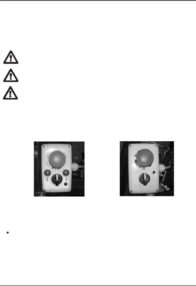
There is a control position which will be identified as the emergency control position. This is located on the ground part of the machine, next to the distributor for the aerial part. To ena ble it, press the special selector positioned on the base of the turret (see photo) until the green warning light comes on. The light indicates that the movements of the aerial part are ena bled.
THERMIC MOTOR |
|
LITHIUM MOTOR |
|
|
|
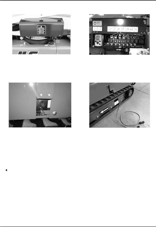
From this position, the movements of the machine can be controlled directly using the levers on the various hydraulic distributors, aerial part (see photo 1) and proportional (aerial part, see photo 2).
 ATTENZIONEDANGER
The emergency control position was designed to operate on the extensible structure only for emergency operations by emergency service personnel on the ground, who must in any case be trained and know the operation of the machine and its safety devices, as well as for maintenance and checks before starting work.
If an operator is in the basket, it is forbidden to move the structure from the ground posi tion, unless in an emergency situation (sudden operator illness, technical fault).
10 |
X20JPR0020413 |
BOOM LIFT MODELS X20JPLUS
JLG
FOTO 1 |
|
FOTO 2 |
There is a control position available only for scheduled and unscheduled maintenance opera tions, placed near the electrical components compartment on the machine.
On the electric board protection there is an auxiliary connector for the connection of the optional second remote control (see photo).
OPTIONAL SECOND REMOTE |
OPTIONAL SECOND REMOTE |
CONTROL CONNECTOR POSITION |
CONTROL CONNECTOR |
To enable this position, use the key selector placed on the base of the turret and connect the optional second remote control to the machine.
Before proceeding with the connection, carefully read the paragraph regarding the use of the optional second remote control.
 ATTENZIONEDANGER
This control position can only be used to carry out checks and maintenance on the machine. Do not use this position to control the machine during normal operations.
Note: it is absolutely forbidden to move the machine from this position if one ore more operators are in the basket.
X20JPR0020413 |
11 |
BOOM LIFT MODELS X20JPLUS
JLG
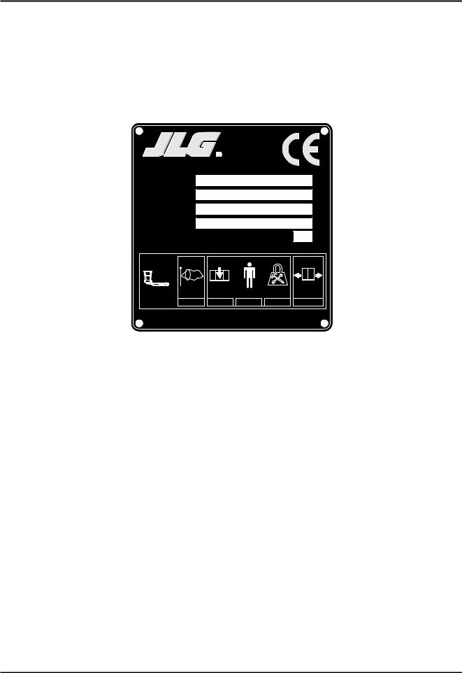
2.1.2 MACHINE IDENTIFICATION PLATE
The manufacturer plate is placed on the protection of the aerial part hydraulic distributor. The drawing is shown below.
|
xsm1;Manufactured by |
|
HINOWA S.p.A. |
|
Via Fontana |
JLG Industries. Inc - McConnellsburg. PA - USA |
37054 NOGARA (VR) |
ITALY |
Model
Serial number
Date of manufacture
G.V.W. (Dry) |
kg |
MAXIMUM ALLOWABLE OPERATING INCLINATION |
1° |
|
|
|
|
= |
+ |
|
|
|
|
MAX |
|
|
|
|
|
|
|
|
|
12.5 |
M/S |
230 |
kg |
2x80 |
kg |
70 |
kg |
400 |
N |
|
|
|
|
|
|
|
|
07253100 |
|
12 |
X20JPR0020413 |
BOOM LIFT MODELS X20JPLUS
JLG
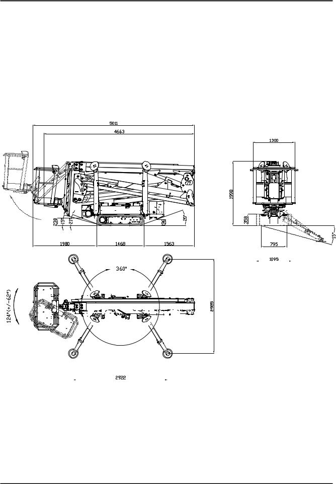
2.1.3 OVERALL DIMENSIONS OF THE MACHINE |
|
|
|
|
|
|
|
|
|
|
|
|||||||||||||||||||||||||||||||||||||||||||||||||||
Maximum length in travel configuration with basket installed ...................... |
|
5011 mm |
||||||||||||||||||||||||||||||||||||||||||||||||||||||||||||
Track width .............................................................................................................. |
|
795/1095 mm |
||||||||||||||||||||||||||||||||||||||||||||||||||||||||||||
Maximum height in travel configuration with foot plates removed .............. |
|
1998 mm |
||||||||||||||||||||||||||||||||||||||||||||||||||||||||||||
Maximum attachment angle.................................................................................. |
20°/ 36,4% |
|||||||||||||||||||||||||||||||||||||||||||||||||||||||||||||
Maximum stabilisation angle ................................................................................ |
15° |
|
|
|
|
|
||||||||||||||||||||||||||||||||||||||||||||||||||||||||
Max stabiliser base side (disc centre) .................................................................. |
|
2922x2925 mm |
||||||||||||||||||||||||||||||||||||||||||||||||||||||||||||
|
|
|
|
|
|
|
|
|
|
|
|
|
|
|
|
|
|
|
|
|
|
|
|
|
|
|
|
|
|
|
|
|
|
|
|
|
|
|
|
|
|
|
|
|
|
|
|
|
|
|
|
|
|
|
|
|
|
|
|
|
|
|
|
|
|
|
|
|
|
|
|
|
|
|
|
|
|
|
|
|
|
|
|
|
|
|
|
|
|
|
|
|
|
|
|
|
|
|
|
|
|
|
|
|
|
|
|
|
|
|
|
|
|
|
|
|
|
|
|
|
|
|
|
|
|
|
|
|
|
|
|
|
|
|
|
|
|
|
|
|
|
|
|
|
|
|
|
|
|
|
|
|
|
|
|
|
|
|
|
|
|
|
|
|
|
|
|
|
|
|
|
|
|
|
|
|
|
|
|
|
|
|
|
|
|
|
|
|
|
|
|
|
|
|
|
|
|
|
|
|
|
|
|
|
|
|
|
|
|
|
|
|
|
|
|
|
|
|
|
|
|
|
|
|
|
|
|
|
|
|
|
|
|
|
|
|
|
|
|
|
|
|
|
|
|
|
|
|
|
|
|
|
|
|
|
|
|
|
|
|
|
|
|
|
|
|
|
|
|
|
|
|
|
|
|
|
|
|
|
|
|
|
|
|
|
|
|
|
|
|
|
|
|
|
|
|
|
|
|
|
|
|
|
|
|
|
|
|
|
|
|
|
|
|
|
|
|
|
|
|
|
|
|
|
|
|
|
|
|
|
|
|
|
|
|
|
|
|
|
|
|
|
|
|
|
|
|
|
|
|
|
|
|
|
|
|
|
|
|
|
|
|
|
|
|
|
|
|
|
|
|
|
|
|
|
|
|
|
|
|
|
|
|
|
|
|
|
|
|
|
|
|
|
|
|
|
|
|
|
|
|
|
|
|
|
|
|
|
|
|
|
|
|
|
|
|
|
|
|
|
|
|
|
|
|
|
|
|
|
|
|
|
|
|
|
|
|
|
|
|
|
|
|
|
|
|
|
|
|
|
|
|
|
|
|
|
|
|
|
|
|
|
|
|
|
|
|
|
|
|
|
|
|
|
|
|
|
|
|
|
|
|
|
|
|
|
|
|
|
|
|
|
|
|
|
|
|
|
|
|
|
|
|
|
|
|
|
|
|
|
|
|
|
|
|
|
|
|
|
|
|
|
|
|
|
|
|
|
|
|
|
|
|
|
|
|
|
|
|
|
|
|
|
|
|
|
|
|
|
|
|
|
|
|
|
|
|
|
|
|
|
|
|
|
|
|
|
|
|
|
|
|
|
|
|
|
|
|
|
|
|
|
|
|
|
|
|
|
|
|
|
|
|
|
|
|
|
|
|
|
|
|
|
|
|
|
|
|
|
|
|
|
|
|
|
|
|
|
|
|
|
|
|
|
|
|
|
|
|
|
|
|
|
|
|
|
|
|
|
|
|
|
|
|
|
|
|
|
|
|
|
|
|
|
|
|
|
|
|
|
|
|
|
|
|
|
|
|
|
|
|
|
|
|
|
|
|
|
|
|
|
|
|
|
|
|
|
|
|
|
|
|
|
|
|
|
|
|
|
|
|
|
|
|
|
|
|
|
|
|
|
|
|
|
|
|
|
|
|
|
|
|
|
|
|
|
|
|
|
|
|
|
|
|
|
|
|
|
|
|
|
|
|
|
|
|
|
|
|
|
|
|
|
|
|
|
|
|
|
|
|
|
|
|
|
|
|
|
|
|
|
|
|
|
|
|
|
|
|
|
|
|
|
|
|
|
|
|
|
|
|
|
|
|
|
|
|
|
|
|
|
|
|
|
|
|
|
|
|
|
|
|
|
|
|
|
|
|
|
|
|
|
|
|
|
|
|
|
|
|
|
|
|
|
|
|
|
|
|
|
|
|
|
|
|
|
|
|
|
|
|
|
|
|
|
|
|
|
|
|
|
|
|
|
|
|
|
|
|
|
|
|
|
|
|
|
|
|
|
|
|
|
|
|
|
|
|
|
|
|
|
|
|
|
|
|
|
|
|
|
|
|
|
|
|
|
|
|
|
|
|
|
|
|
|
|
|
|
|
|
|
|
|
|
|
|
|
|
|
|
|
|
|
|
|
|
|
|
|
|
|
|
|
|
|
|
|
|
|
|
|
|
|
|
|
|
|
|
|
|
|
|
|
|
|
|
|
|
|
|
|
|
|
|
|
|
|
|
|
|
|
|
|
|
|
|
|
|
|
|
|
|
|
|
|
|
|
|
|
|
|
|
|
|
|
|
|
|
|
|
|
|
|
|
|
|
|
|
|
|
|
|
|
|
|
|
|
|
|
|
|
|
|
|
|
|
|
|
|
|
|
|
|
|
|
|
|
|
|
|
|
|
|
|
|
|
|
|
|
|
|
|
|
|
|
|
|
|
|
|
|
|
|
|
|
|
|
|
|
|
|
|
|
|
|
|
|
|
|
|
|
|
|
|
|
|
|
|
|
|
|
|
|
|
|
|
|
|
|
|
|
|
|
|
|
|
|
|
|
|
|
|
|
|
|
|
|
|
|
|
|
|
|
|
|
|
|
|
|
|
|
|
|
|
|
|
|
|
|
|
|
|
|
|
|
|
|
|
|
|
|
|
|
|
|
|
|
|
|
|
|
|
|
|
|
|
|
|
|
|
|
|
|
|
|
|
|
|
|
|
|
|
|
|
|
|
|
|
|
|
|
|
|
|
|
|
|
|
|
|
|
|
|
|
|
|
|
|
|
|
|
|
|
|
|
|
|
|
|
|
|
|
|
|
|
|
|
|
|
|
|
|
|
|
|
|
|
|
|
|
|
|
|
|
|
|
|
|
|
Nota: standard version with two operator basket.
X20JPR0020413 |
13 |

BOOM LIFT MODELS X20JPLUS
JLG
2.1.4 TECHNICAL SPECIFICATIONS
PLATFORM CAPACITY |
230 kg |
|
|
|
|
PLATFORM HEIGHT (floor) |
18,05 m |
|
|
|
|
MAX WORKING HEIGHT |
20,15 m |
|
|
|
|
STANDARD BASKET DIMENSIONS |
1335 x 690 x H1100 mm |
|
|
|
|
MAX HORIZONTAL EXTENSION IN BASKET |
9,20 m |
|
|
|
|
MAX HORIZONTAL OUTREACH |
9,70 m |
|
|
|
|
ROTATION (non-continuous) |
360° |
|
|
|
|
BASKET ROTATION |
124° (+/- 62°) |
|
|
|
|
MAX GROUND REACTION FORCE FOR EACH |
2150 daN |
|
STABILISER |
||
|
||
|
|
|
MAX GROUND PRESSURE FOR EACH STABILISER |
3,04 daN/cm2 |
|
|
|
|
NO. OF OPERATORS |
2 |
|
|
|
|
NO. OF OPERATORS WITH OPTIONAL SINGLE-OPERATOR |
1 |
|
BASKET |
||
|
||
|
|
|
JIB - TYPE OF ARTICULATED JOINT |
89°(+0°/-89°) |
|
|
|
|
MAX WORKING GRADIENT |
1°/1,75% |
|
|
|
|
MAX STABILISATION SLOPE |
15° |
|
|
|
|
TOTAL WEIGHT IN TRANSPORT CONFIGURATION |
2880 kg |
|
(PETROL ENGINE) |
||
|
||
|
|
|
ENGINE |
HONDA iGX440 - (12,7 cv) / 3600 rpm |
|
PERKINS 402.05 - (14 cv) / 3600 rpm |
||
|
||
|
|
|
ELECTRIC MOTOR |
2,2 kw / 230V / 50Hz 1500 rpm |
|
|
|
|
ELECTRICAL SYSTEM VOLTAGE |
12 V |
|
|
|
|
PUMPS PETROL ENGINE |
double 2x4 cm³ |
|
|
|
|
PUMPS DIESEL ENGINE |
double 2x4 cm³ |
|
|
|
|
MAX TRANSLATION SPEED WITH STANDARD 2ND SPEED |
0,5/1,3 / 2,5 Km/h |
|
(thermic motor) |
||
|
||
|
|
|
TRAVEL/STAB. SYSTEM PRESSURE |
165 bar |
|
|
|
|
AERIAL PART SYSTEM PRESSURE |
210 bar |
|
|
|
|
MAX SLOPE ALLOWED IN TRAVEL DIRECTION |
15° |
|
|
|
|
MAX WIND SPEED |
12,5 m/s |
|
|
|
|
MAX MANUAL FORCE ALLOWED |
400 N |
|
|
|
NB: Side extension is measured from the centre of the turntable to the outside edge of the basket.
14 |
X20JPR0020413 |

BOOM LIFT MODELS X20JPLUS |
|
JLG |
|
2.1.4.1 TECHNICAL DATA – PETROL ENGINE |
|
Make/Model ................................................................................ |
HONDA iGX440 |
Fuel/Cooling ................................................................................ |
PETROL/AIR |
Power SAEJ1349 .......................................................................... |
9,5 Kw (12,7cv) / 3600rpm |
Max speed .................................................................................... |
3600 rpm |
Maximum torque ........................................................................ |
29,8 Nm/2500 rpm (80/1269/EC) |
Number of cylinders ............................................................................ |
1 |
Displacement .............................................................................. |
440 cm3 |
Sound power level at operator’s ear ........................................ |
88 dB |
Measured sound power level .................................................. |
102 dB |
Granted sound power level ...................................................... |
104 dB |
2.1.4.2 TECHNICAL DATA – DIESEL ENGINE |
|
Make/Model ................................................................................ |
PERKINS 402.05 |
Fuel/Cooling ................................................................................ |
DIESEL/AIR |
Power SAEJ1349 .......................................................................... |
10,2 Kw (14cv) / 3600rpm |
Max speed .................................................................................... |
3500 rpm |
Maximum torque ........................................................................ |
29,7 Nm/2400 rpm (80/1269/EC) |
Number of cylinders ............................................................................ |
2 |
Displacement .............................................................................. |
510 cm3 |
Sound power level at operator’s ear ........................................ |
90 dB |
Measured sound power level .................................................. |
102 dB |
Granted sound power level ...................................................... |
104 dB |
2.1.4.3 HYDRAULIC SYSTEM TECHNICAL SPECIFICATIONS
Hydraulic oil tank capacity ...................................................... |
40 litres |
Pump petrol engine .................................................................... |
double pump 2x4 cm3 |
Pump diesel engine .................................................................... |
double pump 2x4 cm3 |
Hydraulic system max pressure .............................................. |
210 bars |
For further information, see the hydraulic diagram enclosed with the manual and the para graph on maintenance of the hydraulic components.
X20JPR0020413 |
15 |

BOOM LIFT MODELS X20JPLUS
JLG
2.1.4.4 ELECTRICAL SYSTEM TECHNICAL SPECIFICATIONS THERMIC
Battery ................................................................................ |
55 Ah 240 A 12V |
Alternator petrol engine .................................................. |
20 A (3600 rpm) |
Alternator diesel engine .................................................. |
15 A (3600 rpm) |
Electric motor: rated voltage ...................................... |
230 V |
frequency............................................ |
50 Hz |
rated power ........................................ |
2,2 kW |
For further information, see wiring diagram enclosed with the manual and the paragraph on maintenance of electrical components.
2.1.4.5 ELECTRICAL SYSTEM TECHNICAL SPECIFICATIONS LITHIUM
Battery ................................................................................ |
90 Ah 70V |
Electric motor: rated voltage ...................................... |
48 V |
rated power ........................................ |
2 kW |
Sound power level at operator’s ear .............................. |
70 dB |
Measured sound power level .......................................... |
86 dB |
Granted sound power level.............................................. |
88 dB |
Onboard battery charger .................................................. |
220V±30V 50÷60Hz |
Battery charger (option).................................................... |
110V±30V 50÷60Hz |
For further information, see wiring diagram enclosed with the manual and the paragraph on maintenance of electrical components.
16 |
X20JPR0020413 |
BOOM LIFT MODELS X20JPLUS
JLG
2.1.5 TERMINOLOGY
To make the contents of this manual easier to understand, the diagram provided below illu strates the terms used to identify the parts of the platform.
LEGENDA
1 |
Tracked undercarriage |
19 |
First extension arm |
|
|
|
|
2 |
Revolving turret |
20 |
Jib cylinder |
|
|
|
|
3 |
Turntable + rotation motor |
21 |
Right and left Jib arm |
|
|
|
|
4 |
Emergency controls |
22 |
Second extension arm |
|
|
|
|
5 |
Base+electrical component compartment+oil tank |
23 |
Remote control |
|
|
|
|
6 |
Double gear pump |
24 |
Basket or cage |
|
|
|
|
7 |
Petrol/diesel engine / Battery pack + inverter + |
25 |
Basket support |
|
battery charger (LITHIUM MOTOR) |
|
|
8 |
Stabiliser |
26 |
Rotary actuator for basket rotation |
|
|
|
|
9 |
Stabiliser cylinder |
27 |
Basket levelling cylinder on the basket |
|
|
|
|
10 |
Second arm tie rod |
28 |
Jib transmission |
|
|
|
|
11 |
Second arm |
29 |
First-second arm transmission |
|
|
|
|
12 |
Second-third arm cylinder |
30 |
First-second arm cylinder |
|
|
|
|
13 |
Second-third arm transmission |
31 |
First arm |
|
|
|
|
14 |
Second-third arm connecting rod |
32 |
|
|
|
|
|
15 |
Basket levelling cylinder on the transmission |
33 |
Electric motor |
|
|
|
|
16 |
Third arm |
34 |
Double gear pump |
|
|
|
|
17 |
Stabiliser plate |
35 |
Emergency hand pump |
|
|
|
|
18 |
Jib tie rod |
|
|
|
|
|
|
|
|
|
|
X20JPR0020413 |
17 |
BOOM LIFT MODELS X20JPLUS
JLG
2.2 GENERAL SAFETY STANDARDS
ATTENZIONEDANGER
The functioning of the MEWP must be in compliance with international standards of referen ce (see paragraph “NORMATIVE REFERENCES” in the first pages of the manual) and natio nal or regional standards if stricter.
The operator must read, understand and follow all the instructions and warnings, contained in this manual and on the machine, regarding the safe use of the MEWP.
FAILURE TO COMPLY WITH THE SAFETY PRECAUTIONS LISTED IN THIS SECTION AND PROVIDED ON THE MACHINE CAN DAMAGE THE MACHINE AND CAUSE INJURY OR EVEN DEATH, AND CONSTITUTES A SERIOUS BREACH OF THE SAFETY RULES.
This section of the USER AND OPERATION MANUAL describes those procedures or dan gerous situations that can cause damage/injury to objects/persons and explains what the ope rator must do to prevent them.
•Operators must always act professionally, complying with safety standards, making sure not to underestimate their responsibility to themselves and the surrounding objects and per sons.
•Before starting work, operators must receive complete and clear training regarding the use of the machine in standard and emergency conditions. They must examine, under stand and take in all the instructions given in this user manual. They must be sure that the safety devices are in perfect working order, perform the necessary checks on the machine and be familiar with the conditions of the ground on which the machine is going to be operated and stabilised.
•The presence of at least one specialist operator is necessary on the ground during work. This person must know how to use the machine, be aware of the contents of the USER AND OPERATION MANUAL and be able to intervene if necessary.
•It is prohibited to make modifications to the machine that could jeopardise functioning and safety, without previous written authorisation from The Constructor which is not liable for any injury or damage caused by this behaviour.
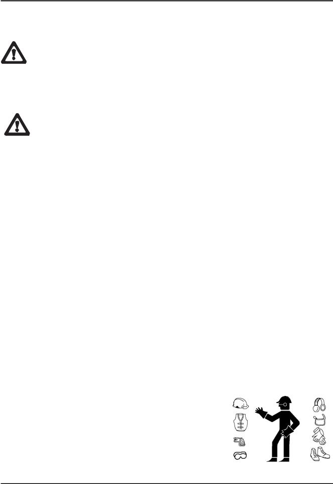
Clothing and protective equipment
Avoid wearing loose clothing, rings, watches or anything else that may get caught in moving parts.
When using the machine or performing maintenance, wear a hard hat, glasses, safety footwear, gloves and acoustic ear muffs after making sure these and all other PPE that the safety manager considers necessary based on the risk analy sis performed are in perfect working condition.
18 |
X20JPR0020413 |
BOOM LIFT MODELS X20JPLUS
JLG
 IMPORTANTEWARNING
USE THE TYPE APPROVED AND CERTIFIED SAFETY HARNESSES. BEFORE WORKING AT A HEIGHT, MAKE SURE THAT THE SAFETY HARNESSES ARE CORRECTLY FASTE NED AND CONNECTED TO THE ANCHORAGE POINTS ON THE BASKET.
THE USE OF HARNESSES IS COMPULSORY IN ACCORDANCE WITH LOCAL LEGISLATION IN EACH INDI VIDUAL COUNTRY. IN COUNTRIES WHERE THE LAW DOES NOT REQUIRE THE USE OF SUCH SAFETY SYSTEMS, THE EMPLOYER AND/OR USER IS RESPONSIBLE FOR CHOOSING THE SYSTEM TO BE USED.
Safety valves and electrical system safety components
It is prohibited to modify and/or tamper with the safety and control valves of the main hydraulic system and the adjustments of the electric plant. The Constructor is not liable for injury to persons and damage to objects or to the machine if the standard calibration of any hydraulic and electric/electronic component is tampered with.
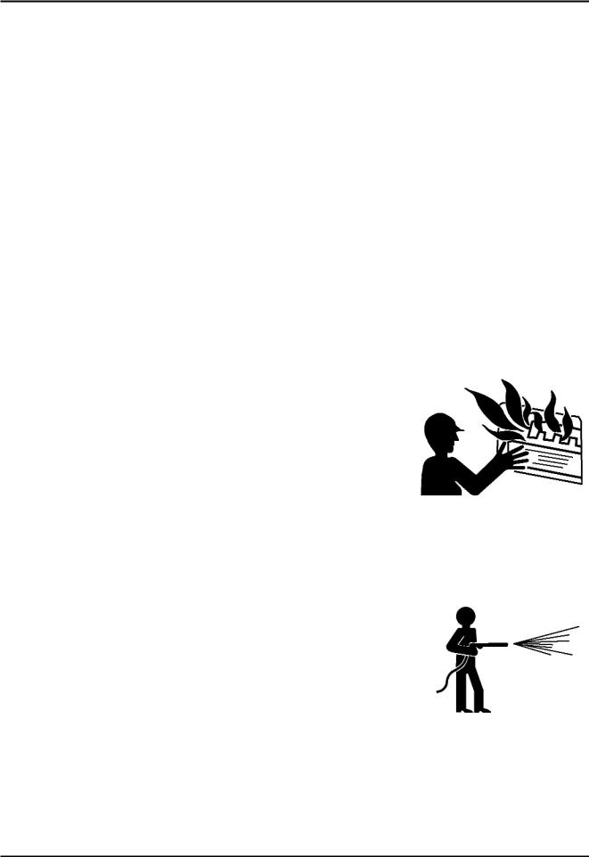
Fire prevention
Keep the area around the motor clean, removing fragments of wood, paper and other flammable products; clean any fuel leaks as these may be a potential cause of fire.
Petrol is extremely flammable and explosive in particular con ditions. Refuel in well ventilated areas and with the engine at rest.
Avoid smoking and producing sparks in the refuelling and fuel storage area.
After refuelling, make sure to put back the cap correctly. Take care to avoid touching the exhaust silencer when this is hot, i.e. with the machine running or soon after stopping the engine.
Preventing damage caused by washing the machine
Do not direct high pressure jets towards the electrical compo nents while washing the machine. Do not use chemical deter gents or petrol that would damage the plastic parts and the painting.
BEFORE WASHING THE MACHINE, ALWAYS REMEMBER TO REMOVE THE REMO TE CONTROL AND CORRECTLY CLOSE THE REMOTE CONTROL AND EQUIP MENT CONNECTION SOCKETS LOCATED ON THE MACHINE.
X20JPR0020413 |
19 |
BOOM LIFT MODELS X20JPLUS
JLG
as shown in the figure in point 2.1.5.
ATTENZIONEDANGER
When washing the machine, the ignition block must be disengaged, the key removed and the emergency stop button pressed.
• Washing the outside of the machine
Never use flammable liquids. Adopt the above safety measures to prevent sparks due to short circuits.
If washing the track with water cleaners, carefully protect all the important parts and above all the electrical components. Follow the instructions provided by the manufacturer of the detergent.
1001125483
Clean the machine using water soluble detergents.
IMPORTANT
The more the elevating platform is cleaned, the more it will need to be greased (see par. 7.3 Grease points).
ATTENZIONEDANGER
Do not wet the electric motors and the other electrical components directly. Do not aim the spray directly onto adhesive labels and rating plates.
• Cleaning the electrical system
 ATTENZIONEDANGER
Never clean the inverter or the electric motor with water, as this may
cause damage to the electrical system.
1001125483
20 |
X20JPR0020413 |

BOOM LIFT MODELS X20JPLUS
JLG
 IMPORTANTEWARNING
Only use dry detergents, in accordance with the manufacturer’s instructions. Never remove covers, guards and the like.
Clean the electrical system using a dry, non metallic brush and low pressure air.
• After cleaning
Dry the machine carefully before starting it again (for example using compressed air).
 ATTENZIONEDANGER
If, despite all the precautions, moisture has penetrated into the electric motor or other parts of the electric system, these must be dried using compressed air to avoid the risk of short cir cuits.
Preventing damage that may be caused by the machine during work
When the machine has been stabilised and work has started, never enter its operating area. Always operate the controls slowly and smoothly and avoid reversing the movements sud denly.
When operating outside of the basket, ALWAYS keep a MINIMUM distance of 1 METRE from the machine.
X20JPR0020413 |
21 |

BOOM LIFT MODELS X20JPLUS
JLG
2.3 SAFETY WARNINGS
2.3.1 GENERALITIES
To avoid accidents, before starting work and before performing any maintenance operations, it is necessary to read, understand and follow all the precautions and warnings contained in this manual. The user/operator of the machine must decline all responsibility for operation until having read this manual and fully understood how to use the machine under the supervision of an expert and qualified operator.
Carefully read all the safety messages provided in this manual and machine.
Keep the safety signs in good condition and replace them if they are Make sure that any new components on the machine are provided with
2.3.2 NOISE AND VIBRATIONS
The JLG platforms with electric motor have been tested according to pean directive 2000/14 EC, with the guaranteed sound power level the machine’s EC declaration of conformity.
When operating the aerial part of the machine, this value is reduced basket moves away from the main source of noise.
The vibrations transmitted to the operator from the controls and the basket are lower than the maximum allowed limits.
22
BOOM LIFT MODELS X20JPLUS
JLG
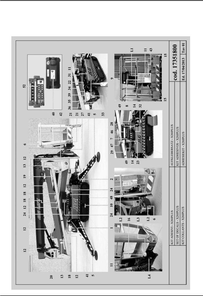
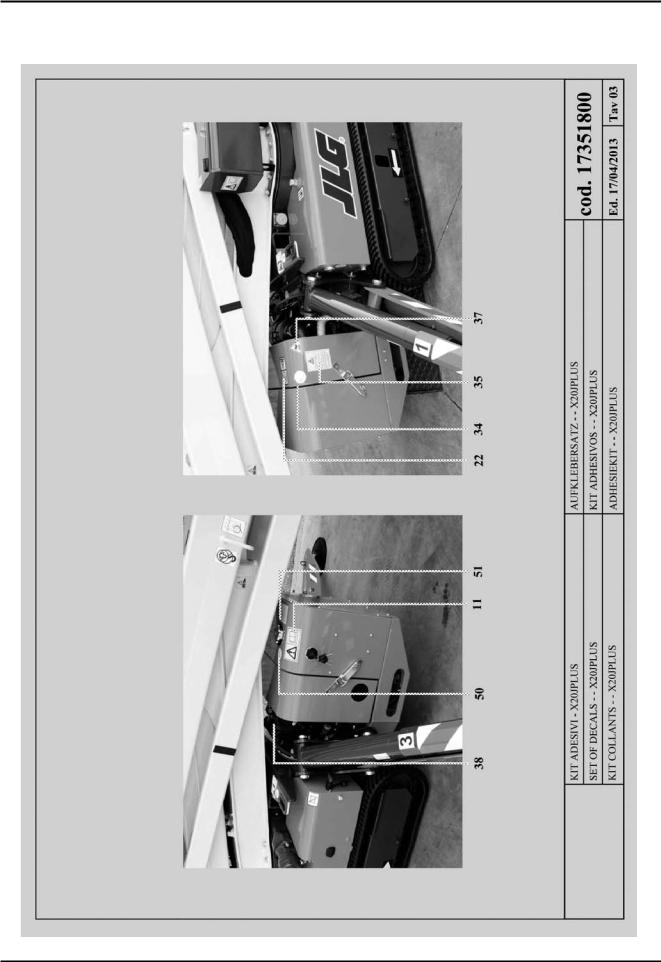
2.3.3 PICTOGRAMS POSITIONED ON THE MACHINE
Here we report the positions of the various boards with pictograms on the machine.
X20JPR0020413 |
23 |

BOOM LIFT MODELS X20JPLUS
JLG
24 |
X20JPR0020413 |
BOOM LIFT MODELS X20JPLUS
JLG
X20JPR0020413 |
25 |

BOOM LIFT MODELS X20JPLUS
JLG
POS. |
CODE |
Q.ty |
1 |
6555500 |
1 |
2 |
6555600 |
1 |
3 |
6555700 |
1 |
4 |
6555800 |
1 |
5 |
6041200 |
4 |
6 |
1001125483 |
6 |
7 |
1706898 |
1 |
8 |
6924300 |
1 |
9 |
1706493 |
1 |
10 |
6040500 |
2 |
11 |
6040900 |
6 |
12 |
6041300 |
11 |
13 |
1703814 |
4 |
14 |
6044000 |
4 |
15 |
6086600 |
2 |
16 |
1704277 |
2 |
17 |
1705828 |
1 |
18 |
7056700 |
6 |
19 |
1701499 |
2 |
20 |
7058800 |
2 |
21 |
6040300 |
4 |
22 |
1706098 |
1 |
23 |
7349200 |
1 |
24 |
7056800 |
3 |
25 |
06086000 |
1 |
26 |
06085900 |
1 |
27 |
06706500 |
1 |
28 |
06998800 |
1 |
29 |
07242000 |
1 |
30 |
1702155 |
1 |
31 |
1701504 |
1 |
32 |
06164700 |
1 |
33 |
06165000 |
1 |
34 |
06060000 |
1 |
35 |
06227200 |
1 |
POS. |
CODE |
Q.ty |
36 |
1701542 |
1 |
36 |
1701505 |
1 |
37 |
06056300 |
1 |
38 |
06164600 |
1 |
39 |
06232100 |
1 |
40 |
07240300 |
1 |
41 |
07320400 |
4 |
42 |
07034200 |
2 |
43 |
07397200 |
1 |
44 |
1608710001 |
1 |
45 |
1608710002 |
1 |
46 |
07199100 |
1 |
47 |
06254800 |
1 |
48 |
06922700 |
2 |
49 |
07350300 |
4 |
50 |
06214200 |
1 |
51 |
06594500 |
1 |
52 |
07071000 |
1 |
53 |
06136900 |
1 |
|
|
|
26 |
X20JPR0020413 |
 Loading...