

Page 1

Illustrated Parts Manual
Models
25RTS
33RTS
40RTS
P/N - 3120692
March 15, 2012
Page 2

Page 3

REVISION LOG
March 1993 - Original Issue Of Manual
October 1998 - Revised
January 7, 2000 - Revised (25RTS Manual edited to 0010450 Revision 35)
(33RTS Manual edited to 0010451 Revision 33)
(40RTS Manual edited to 0010452 Revision 34)
March 1, 2000 - Updated Page 1-2
May 16, 2000 - Updated Page 4-16 & 4-19
April 1, 2001 - Revised (25RTS Manual edited to 0010450 Revision 43)
(33RTS Manual edited to 0010451 Revision 40)
(40RTS Manual edited to 0010452 Revision 42)
April 8, 2002 - Revised (25RTS Manual edited to 0010450 Revision 48)
(33RTS Manual edited to 0010451 Revision 46)
(40RTS Manual edited to 0010452 Revision 47)
March 21, 2003 - Revised (25RTS Manual edited to 0010450 Revision 49)
(33RTS Manual edited to 0010451 Revision 47)
(40RTS Manual edited to 0010452 Revision 49)
December 31, 2006 - Revised (25RTS Manual edited to 0010450 Revision 50)
(33RTS Manual edited to 0010451 Revision 47)
(40RTS Manual edited to 0010452 Revision 49)
June 5, 2009 - Revised (25RTS Manual edited to 0010450 Revision 50)
(33RTS Manual edited to 0010451 Revision 47)
(40RTS Manual edited to 0010452 Revision 49)
March 15, 2012 - Revised
3120692 A
Page 4

REVISION LOG
B 3120692
Page 5

TABLE OF CONTENTS
FIGURE NO. TITLE PAGE NO.
SECTION 1 - FRAME . . . . . . . . . . . . . . . . . . . . . . . . . . . . . . . . . . . . . . . . . . . . . . . . . . . . . .1-1
1-1 FRAME, STEERING AND AXLE INSTALLATIONS. . . . . . . . . . . . . . . . . . . . . . . . . . . . . .1-2
1-2 LOCKOUT VALVE ASSEMBLY . . . . . . . . . . . . . . . . . . . . . . . . . . . . . . . . . . . . . . . . . . . .1-8
1-3 TIRE AND WHEEL DRIVE INSTALLATIONS . . . . . . . . . . . . . . . . . . . . . . . . . . . . . . . . . .1-10
1-4 DRIVE MOTOR ASSEMBLY. . . . . . . . . . . . . . . . . . . . . . . . . . . . . . . . . . . . . . . . . . . . . . .1-14
1-5 DRIVE BRAKE ASSEMBLY . . . . . . . . . . . . . . . . . . . . . . . . . . . . . . . . . . . . . . . . . . . . . . .1-16
1-6 DRIVE HUB ASSEMBLIES . . . . . . . . . . . . . . . . . . . . . . . . . . . . . . . . . . . . . . . . . . . . . . . .1-20
1-7 DRIVE HUB/BRAKE ASSEMBLIES . . . . . . . . . . . . . . . . . . . . . . . . . . . . . . . . . . . . . . . . .1-24
1-8 FRAME MOUNTED COMPONENTS INSTALLATION . . . . . . . . . . . . . . . . . . . . . . . . . . .1-30
1-9 LEVELING JACK (WITH INTERLOCK) AND LIGHTS INSTALLATION
(FRAME MOUNTED). . . . . . . . . . . . . . . . . . . . . . . . . . . . . . . . . . . . . . . . . . . . . . . . . . .1-34
1-10 LEVELING JACK (WITHOUT INTERLOCK) INSTALLATION . . . . . . . . . . . . . . . . . . . . . .1-38
1-11 TOW PACKAGE INSTALLATION (OPTIONAL) . . . . . . . . . . . . . . . . . . . . . . . . . . . . . . . .1-42
SECTION 2 - GROUND COMPONENTS . . . . . . . . . . . . . . . . . . . . . . . . . . . . . . . . . . . . . . .2-1
2-1 CONTROL VALVES AND TANKS INSTALLATION. . . . . . . . . . . . . . . . . . . . . . . . . . . . . .2-2
2-2 CONTROL VALVE ASSEMBLY (PRIOR TO S/N 26763) . . . . . . . . . . . . . . . . . . . . . . . . .2-8
2-3 CONTROL VALVE ASSEMBLY (S/N 26763 TO PRESENT) . . . . . . . . . . . . . . . . . . . . . .2-12
2-4 CONTROL VALVE ASSEMBLY - FPS 4 STACK (LEVELING JACKS OPTION). . . . . . . .2-14
2-5 ENGINE INSTALLATION - FORD VSG-411 . . . . . . . . . . . . . . . . . . . . . . . . . . . . . . . . . . .2-16
2-6 ENGINE INSTALLATION - FORD VSG-413 . . . . . . . . . . . . . . . . . . . . . . . . . . . . . . . . . . .2-24
2-7 DUAL FUEL COMPONENTS INSTALLATION (FORD ENGINE OPTION). . . . . . . . . . . .2-32
2-8 GENERATOR INSTALLATION (FORD ENGINE OPTION). . . . . . . . . . . . . . . . . . . . . . . .2-36
2-9 ENGINE INSTALLATION - DEUTZ F2L1011 . . . . . . . . . . . . . . . . . . . . . . . . . . . . . . . . . .2-38
2-10 GENERATOR INSTALLATIONS (DEUTZ ENGINE OPTION). . . . . . . . . . . . . . . . . . . . . .2-44
2-11 PISTON PUMP ASSEMBLY - SUNSTRAND . . . . . . . . . . . . . . . . . . . . . . . . . . . . . . . . . .2-48
2-12 GEAR PUMP ASSEMBLY - JSB. . . . . . . . . . . . . . . . . . . . . . . . . . . . . . . . . . . . . . . . . . . .2-52
2-13 GROUND CONTROL BOX INSTALLATION . . . . . . . . . . . . . . . . . . . . . . . . . . . . . . . . . . .2-54
2-14 HOODS AND BEACON LIGHT INSTALLATION . . . . . . . . . . . . . . . . . . . . . . . . . . . . . . .2-58
SECTION 3 - SIZZOR ARMS . . . . . . . . . . . . . . . . . . . . . . . . . . . . . . . . . . . . . . . . . . . . . . . .3-1
3-1 SIZZOR ARMS INSTALLATION - 40RTS . . . . . . . . . . . . . . . . . . . . . . . . . . . . . . . . . . . . .3-2
3-2 SIZZOR ARMS INSTALLATION - 33RTS . . . . . . . . . . . . . . . . . . . . . . . . . . . . . . . . . . . . .3-6
3-3 SIZZOR ARMS INSTALLATION - 25RTS . . . . . . . . . . . . . . . . . . . . . . . . . . . . . . . . . . . . .3-10
SECTION 4 - PLATFORM. . . . . . . . . . . . . . . . . . . . . . . . . . . . . . . . . . . . . . . . . . . . . . . . . . .4-1
4-1 FIXED PLATFORM (STANDARD) & OPTIONAL COMPONENTS INSTALLATIONS . . . .4-2
4-2 PLATFORM EXTENDABLE INSTALLATIONS (PRIOR TO S/N 50308) . . . . . . . . . . . . . .4-6
4-3 PLATFORM EXTENDABLE INSTALLATIONS (S/N 50308 TO PRESENT) . . . . . . . . . . .4-10
4-4 PLATFORM CONSOLE BOX INSTALLATION . . . . . . . . . . . . . . . . . . . . . . . . . . . . . . . . .4-12
4-5 DRIVE/LIFT CONTROLLER ASSEMBLY (PRIOR TO S/N 57701) . . . . . . . . . . . . . . . . . .4-16
4-6 DRIVE/LIFT CONTROLLER ASSEMBLY (S/N 57701 TO PRESENT) . . . . . . . . . . . . . . .4-18
SECTION 5 - CYLINDERS . . . . . . . . . . . . . . . . . . . . . . . . . . . . . . . . . . . . . . . . . . . . . . . . . .5-1
5-1 AXLE LOCKOUT CYLINDER ASSEMBLY (OSCILLATING AXLE OPTION). . . . . . . . . . .5-2
5-2 LEVELING JACK CYLINDER ASSEMBLY WITH SCREW-IN PIVOT PAD (HYDRAULIC
JACK OPTION WITHOUT INTERLOCK - PRODUCTION CYLINDERS) . . . . . . . . . . . .5-4
5-3 LEVELING JACK CYLINDER ASSEMBLY WITH WELDED ON PIVOT PAD (HYDRAULIC
JACK OPTION WITHOUT INTERLOCK - RECOMMENDED SERVICE REPLACEMENT
CYLINDERS) . . . . . . . . . . . . . . . . . . . . . . . . . . . . . . . . . . . . . . . . . . . . . . . . . . . . . . . . .5-8
3120692 i
Page 6

TABLE OF CONTENTS
FIGURE NO. TITLE PAGE NO.
5-4 LEVELING JACK CYLINDER ASSEMBLY (HYDRAULIC JACK OPTION WITH
INTERLOCK). . . . . . . . . . . . . . . . . . . . . . . . . . . . . . . . . . . . . . . . . . . . . . . . . . . . . . . . .5-10
5-5 LIFT CYLINDER ASSEMBLIES . . . . . . . . . . . . . . . . . . . . . . . . . . . . . . . . . . . . . . . . . . . . 5-12
5-6 STEER CYLINDER ASSEMBLY (MACHINES BUILT PRIOR TO JUNE 1993). . . . . . . . . 5-16
5-7 STEER CYLINDER ASSEMBLY (MACHINES BUILT JUNE 1993 TO PRESENT) . . . . . . 5-18
SECTION 6 - HYDRAULICS. . . . . . . . . . . . . . . . . . . . . . . . . . . . . . . . . . . . . . . . . . . . . . . . . 6-1
6-1 HYDRAULIC DIAGRAM LIST . . . . . . . . . . . . . . . . . . . . . . . . . . . . . . . . . . . . . . . . . . . . . . 6-1
6-2 HYDRAULIC DIAGRAM - 2WD/2WS . . . . . . . . . . . . . . . . . . . . . . . . . . . . . . . . . . . . . . . .6-2
6-3 HYDRAULIC DIAGRAM - 4WD/2WS . . . . . . . . . . . . . . . . . . . . . . . . . . . . . . . . . . . . . . . .6-6
6-3 HYDRAULIC DIAGRAM - 4WD/2WS . . . . . . . . . . . . . . . . . . . . . . . . . . . . . . . . . . . . . . . .6-7
6-4 HYDRAULIC DIAGRAM - 4WD/4WS . . . . . . . . . . . . . . . . . . . . . . . . . . . . . . . . . . . . . . . .6-12
6-4 HYDRAULIC DIAGRAM - 4WD/4WS . . . . . . . . . . . . . . . . . . . . . . . . . . . . . . . . . . . . . . . .6-13
6-5 HYDRAULIC DIAGRAM - AXLE (OSCILLATING). . . . . . . . . . . . . . . . . . . . . . . . . . . . . . .6-16
SECTION 7 - ELECTRICAL . . . . . . . . . . . . . . . . . . . . . . . . . . . . . . . . . . . . . . . . . . . . . . . . . 7-1
7-1 ELECTRICAL DIAGRAMS AND COMPONENTS LIST. . . . . . . . . . . . . . . . . . . . . . . . . . .7-2
7-2 ELECTRICAL DIAGRAM - DUAL FUEL (FORD ENGINE OPTION). . . . . . . . . . . . . . . . .7-7
7-3 ELECTRICAL DIAGRAM - 110V GENERATOR.. . . . . . . . . . . . . . . . . . . . . . . . . . . . . . . .7-8
7-4 ELECTRICAL DIAGRAM - 0610114 CIRCUIT CARD. . . . . . . . . . . . . . . . . . . . . . . . . . . .7-9
7-5 ELECTRICAL DIAGRAM - DEUTZ ENGINE MACHINES (PRIOR TO S/N 61097). . . . . . 7-10
7-5 ELECTRICAL DIAGRAM - DEUTZ ENGINE MACHINES (PRIOR TO S/N 61097). . . . . . 7-11
7-6 ELECTRICAL DIAGRAM - DEUTZ ENGINE MACHINES (S/N 61097 TO PRESENT). . .7-12
7-6 ELECTRICAL DIAGRAM - DEUTZ ENGINE MACHINES (S/N 61097 TO PRESENT). . .7-13
7-7 ELECTRICAL DIAGRAM - FORD ENGINE MACHINES (PRIOR TO S/N 61097) . . . . . .7-14
7-7 ELECTRICAL DIAGRAM - FORD ENGINE MACHINES (PRIOR TO S/N 61097) . . . . . .7-15
7-8 ELECTRICAL DIAGRAM - FORD ENGINE MACHINES (S/N 61097 TO PRESENT). . . . 7-16
7-8 ELECTRICAL DIAGRAM - FORD ENGINE MACHINES (S/N 61097 TO PRESENT). . . . 7-17
SECTION 8 - DECALS . . . . . . . . . . . . . . . . . . . . . . . . . . . . . . . . . . . . . . . . . . . . . . . . . . . . . 8-1
8-1 DECALS INSTALLATIONS - STANDARD . . . . . . . . . . . . . . . . . . . . . . . . . . . . . . . . . . . .8-2
8-2 DECALS INSTALLATIONS - COUNTRY SPEC . . . . . . . . . . . . . . . . . . . . . . . . . . . . . . . .8-6
SECTION 9 - RECOMMENDED SERVICE PARTS STOCK . . . . . . . . . . . . . . . . . . . . . . . . 9-1
SECTION 10 - SPECIAL OPTIONS LIST. . . . . . . . . . . . . . . . . . . . . . . . . . . . . . . . . . . . . . . 10-1
ii 3120692
Page 7

SECTION 1 FRAME
S
E
TABLE OF CONTENTS
FIGURE DESCRIPTION
1-1 FRAME, STEERING AND AXLE INSTALLATIONS . . . . . . . . . . . . . . . . . . . . . . . . . . . . . . . . . . 1-2
1-2 LOCKOUT VALVE ASSEMBLY . . . . . . . . . . . . . . . . . . . . . . . . . . . . . . . . . . . . . . . . . . . . . . . . . . 1-8
1-3 TIRE AND WHEEL DRIVE INSTALLATIONS . . . . . . . . . . . . . . . . . . . . . . . . . . . . . . . . . . . . . . . 1-10
1-4 DRIVE MOTOR ASSEMBLY . . . . . . . . . . . . . . . . . . . . . . . . . . . . . . . . . . . . . . . . . . . . . . . . . . . . 1-14
1-5 DRIVE BRAKE ASSEMBLY . . . . . . . . . . . . . . . . . . . . . . . . . . . . . . . . . . . . . . . . . . . . . . . . . . . . 1-16
1-6 DRIVE HUB ASSEMBLIES. . . . . . . . . . . . . . . . . . . . . . . . . . . . . . . . . . . . . . . . . . . . . . . . . . . . . 1-20
1-7 DRIVE HUB/BRAKE ASSEMBLIES . . . . . . . . . . . . . . . . . . . . . . . . . . . . . . . . . . . . . . . . . . . . . . 1-24
1-8 FRAME MOUNTED COMPONENTS INSTALLATION . . . . . . . . . . . . . . . . . . . . . . . . . . . . . . . . 1-30
1-9 LEVELING JACKS (WITH INTERLOCK) AND LIGHTS INSTALLATION . . . . . . . . . . . . . . . . . . 1-34
1-10 LEVELING JACKS (WITHOUT INTERLOCK) INSTALLATION. . . . . . . . . . . . . . . . . . . . . . . . . . 1-38
1-11 TOW PACKAGE INSTALLATION . . . . . . . . . . . . . . . . . . . . . . . . . . . . . . . . . . . . . . . . . . . . . . . . 1-42
C
T
I
O
N
1
F
R
A
M
E
3120692 1-1
Page 8

S
51
1
52
101
101A
102
102A
103
104
105
106
107
108
109
110
112
113
114
115
116
117
118
119
118
119
120
121
122
123
124
125
126
127
301
308
302
303
304
305
306
307
309
310
312
313
317
318
319
320
514
505
513
502
513
512
505
514
521
507
510
519
511
509
508
517
515
504
516
407
507
403
503
505
404
504
522
406
506
408
524
408
524
409
525
203
207
206
204
205
208
209
210
201
202
213
212
217
218
219
220
407
507
403
503
505
404
504
522
406
506
408
524
408
524
409
525
401A
501A
401
501
401
501
411
413
414
504
527
529
410
526
411
412
414
504
527
528
418
530
417
533
415 (LEFT)
531 (LEFT)
416 (RIGHT)
532 (RIGHT)
402
501B
501B
521
SECTION 1 FRAME
E
C
T
I
O
N
1
F
R
A
M
E
FIGURE 1-1. FRAME, STEERING AND AXLE INSTALLATIONS
1-2 3120692
Page 9

SECTION 1 FRAME
S
FIGURE 1-1. FRAME, STEERING AND AXLE INSTALLATIONS
FIG & ITEM # PART NUMBER DESCRIPTION QTY. REV.
FRAME WELDMENTS - 2WS Ref.
2360352 Prior to S/N44593 Ref. B
2360465 S/N44593 to Present Ref. 5/D
1 See Note Bushing, Bronze (Sizzor Arm Pivot) 4
0961664 Bushing, Composite (Sizzor Arm Pivot) 2
Note: Use 1 composite-type bushing in place of 2
bronze bushings on machines built prior to May
1993. When using existing pins and new composite
type bushings, Graphokote Lube (P/N 3020028) is
required at installation. When replacing pivot pins,
use chrome pivot pins and composite type bushings.
Chrome pivot pins require no lubrication at installation.
FRAME WELDMENTS - 4WS Ref.
2360347 Prior to S/N44593 Ref. I
2360466 S/N44593 to Present Ref. 5/D
51 See Note Bushing, Bronze (Sizzor Arm Pivot) 4
0961664 Bushing, Composite (Sizzor Arm Pivot) 2
52 0961029 Bushing, Bronze (Kingpin Pivot) 4
Note: Use 1 composite-type bushing in place of 2
bronze bushings on machines built prior to May
1993. When using existing pins and new composite
type bushings, Graphokote Lube (P/N 3020028) is
required at installation. When replacing pivot pins,
use chrome pivot pins and composite type bushings.
Chrome pivot pins require no lubrication at installation.
Ref.
Ref.
E
C
T
I
O
N
1
F
R
A
M
E
STEERING INSTALLATION - 2WD FRONT Ref.
0252790 2WD/2WS Common Machines Built Prior to June
1994
0255005 2WD/2WS Common Mach Built June 1994 to
Present
0252790 2WD/2WS CSA Machines Ref. 3/C
0253059 2WD/4WS Common Machines Built Prior to June
1994
0255006 2WD/4WS Common Mach Built June 1994 to
Present
0253059 2WD/4WS CSA Machines Ref. 8/F
101 Spindle Weldment (Right Side) Options: 1
4130287 Common Machines Built Prior to June 1994
4130317 Common Machines Built June 1994 to Present
4030287 CSA Machines - All
101A 0960523 Bushing, Bronze (Kingpin Pivot) 2
102 Spindle Weldment (Left Side) Options: 1
4130288 Common Machines Built Prior to June 1994
4130316 Common Machines Built June 1994 to Present
4030288 CSA Machines - All
102A 0960523 Bushing, Bronze (Kingpin Pivot) 2
Ref. B
Ref. 2/B
Ref. 5/D
Ref. 6/D
3120692 1-3
Page 10

S
SECTION 1 FRAME
E
C
T
I
O
N
1
F
R
A
M
E
FIGURE 1-1. FRAME, STEERING AND AXLE INSTALLATIONS (CONTINUED)
FIG & ITEM # PART NUMBER DESCRIPTION QTY. REV.
103 1682967 Steer Cylinder Assembly (See Section 5 for Break-
down)
104 1660204 Rod-End (Right Side) 1
105 3322602 Nut, Jam 1" - 12NF Right Hand Threads (Left Side) 1
106 1660205 Rod-End (Left Side) 1
107 3300228 Nut, Jam 1"-12" NF Left Hand Threads (Right
Side)
108 2160002 Fitting, Grease 2
109 0642622 Bolt 1" - 8NC x 2 3/4" 2
110 4712600 Flatwasher 1" Narrow 2
111 0100019 Loctite (Not Shown) A/R
112 3421243 Kingpin 2
113 0440183 Bearing, Thrust 2
114 3323403 Nut, Slotted 1 1/2"-12NF 2
115 3451012 Pin, Cotter 5/16" x 3" 2
116 2780177 Hub, Wheel 2
117 3960353 Seal, Oil 2
118 0440174 Cup, Bearing 4
119 0440175 Cone, Bearing 4
120 3322603 Nut, Slotted 1" -12NF 2
121 4740034 Washer, Hardened 2
122 3450610 Pin, Cotter 3/16" x 2 1/2" 2
123 1120311 Cap, Hub 2
124 0721004 Screw, Machine #10-24NC x 1/2" 6
125 4761000 Lockwasher #10 6
126 3300012 Nut, Wheel 18
127 0630137 Stud, Wheel 18
1
1
STEERING INSTALLATION - 4WD FRONT Ref.
0253078 4WD/2WS Ref. 5/D
0252532 4WD/4WS Ref. 7/E
201 4130279 Spindle Weldment (Right Side) 1
202 4130280 Spindle Weldment (Left Side) 1
203 1682967 Steer Cylinder Assy (See Section 5 for Breakdown) 1
204 1660204 Rod-End (Right Side) 1
205 3322602 Nut, Jam 1"-12NF 1
206 1660205 Rod-End (Left Side) 1
207 3300228 Nut, Jam 1"-12NF Left Hand Thread 1
208 2160003 Fitting, Grease - 45° 4
209 0642622 Bolt 1"-8NC x 2 3/4" 2
210 4712600 Flatwasher 1" Narrow 2
211 0100019 Loctite (Not Shown) A/R
212 3421190 Kingpin 4
213 0440161 Bearing, Thrust 4
214 Not Used
215 Not Used
216 Not Used
217 0641608 Bolt 3/8"-16NC x 1" 8
218 4751600 Flatwasher 3/8" 8
1-4 3120692
Page 11

SECTION 1 FRAME
S
FIGURE 1-1. FRAME, STEERING AND AXLE INSTALLATIONS (CONTINUED)
FIG & ITEM # PART NUMBER DESCRIPTION QTY. REV.
219 1380124 Clip, Retainer (Prior to S/N 69836) 8
220 4920385
221 0100011 Loctite #242 (S/N 69836 to Present) (Not Shown) A/R
0253059 2WD/4WS Common Machines Built Prior to June
0255006 2WD/4WS Common Mach Built June 1994 to
0253059 2WD/4WS CSA Machines Ref. 8/F
0252532 4WD/4WS Ref. 7/E
301 4130279 Spindle Weldment (Left Side) 1
302 4130280 Spindle Weldment (Right Side) 2
303 1682967 Steer Cylinder Assy (See Section 5 for Breakdown) 2
304 1660204 Rod-End (Right Hand) 2
305 3322602 Nut, Jam 1"-12NF 2
306 1660205 Rod-End (Left Hand) 2
307 3300228 Nut, Jam 1"-12NF Left Hand Thread 2
308 2160003 Fitting, Grease - 45° 8
309 0642622 Bolt 1"-8NC x 2 3/4" 4
310 4712600 Flatwasher 1" Narrow 4
311 0100019 Loctite (Not Shown) A/R
312 3421190 Kingpin 8
313 0440161 Bearing, Thrust 8
314 Not Used
315 Not Used
316 Not Used
317 0641608 Bolt 3/8"-16NC x 1" 16
318 4751600 Flatwasher 3/8" 16
319 1380124 Clip, Retainer (Prior to S/N 69836) 16
320 4920385 Wire, Safety (8 Pieces 1 ft./30cm long)
321 0100011 Loctite #242 (S/N 69836 to Present) (Not Shown) A/R
Wire, Safety (4 Pieces 1 ft./30 cm Long)
(Prior to S/N 69836)
STEERING INSTALLATION - 4WS REAR
(OPTIONAL)
1994
Present
(Prior to S/N 69836)
4 ft./1.2m
Ref.
Ref. 5/D
Ref. 6/D
8ft/2.4m
E
C
T
I
O
N
1
F
R
A
M
E
FIXED AXLE INSTALLATION OPTIONS Ref.
0253171 2WD Ref. 4
0253172 4WD Ref. 4
401 Axle Weldment Options: 1
4844129 2WD (Prior to October 1994) 1
4844868 2WD (October 1994 to Present) 1
4844059 4WD (Prior to October 1994) 1
4844867 4WD (October 1994 to Present) 1
401A 0961029 Bushing, Bronze (Kingpin Pivot) (4WD Only) 4
402 0560901 Block, Stop 2
403 0641610 Bolt 3/8"-16NC x 1 1/4" 1
404 4740185 Flatwasher 2
3120692 1-5
Page 12

S
SECTION 1 FRAME
E
C
T
I
O
N
1
F
R
A
M
E
FIGURE 1-1. FRAME, STEERING AND AXLE INSTALLATIONS (CONTINUED)
FIG & ITEM # PART NUMBER DESCRIPTION QTY. REV.
405 0100019 Loctite (Not Shown) A/R
406 4842621 Pin Weldment (Prior to October 1994) 1
3422401 Pin Weldment (October 1994 to Present) 1
407 2160002 Fitting, Grease 1
408 3780183 O-Ring (October 1994 to Present) 2
409 4640812 Valve, Relief (October 1994 to Present) 1
410 3820030 Rivet, Pop 3/16" (September 1995 to Present) 6
411 3311605 Nut 3/8"-16NC (September 1995 to Present) 8
412 0641612 Bolt 3/8" x 1 1/2"-16NC (September 1995 to Pres-
ent)
413 0641614 Bolt 3/8" x 1 3/4"-16NC (September 1995 to Pres-
ent)
414 4751600 Flatwasher (September 1995 to Present) 16
415 0902214 Bracket, L.H. (September 1995 to Present) 1
416 0902215 Bracket, R.H. (September 1995 to Present) 1
417 3440616 Pin, Roll 3/16" x 1" (September 1995 to Present) 4
418 4280298 Strip, Wear 2
OSCILLATING AXLE INSTALLATION - OPTION
(STANDARD PARTS WHEN EQUIPPED)
0252772 2WD (Prior to S/N 97717) Ref. 11
0271467 2WD (S/N 97717 to Present) Ref. 1
0252525 4WD (Prior to S/N 97717) Ref. 12
0271468 4WD (S/N 97717 to Present) Ref. 1
4
4
Ref.
501 Axle Weldment Options: 1
4844129 2WD (Prior to October 1994)
4844868 2WD (October 1994 to Present)
4844059 4WD (Prior to October 1994)
4844867 4WD (October 1994 to Present)
501A 0961029 Bushing, Bronze (Prior to October 1994)
(4WD Machines Only)
501B
502 1682185 Axle Lockout Cylinder Assembly
503 0641608 Bolt 3/8"-16NC x 1" 2
504 4751600 Flatwasher 3/8" 18
505 4761600 Lockwasher 3/8" 4
506 4842621 Pin, Axle Pivot (Prior to October 1994) 1
507 2160002 Fitting, Grease 3
508 3422137 Pin, Attach (Bottom) 2
509 0641510 Bolt 5/16"-18NC x 1 1/4" 2
510 3311505 Locknut 5/16"-18NC 2
511 4751500 Flatwasher 5/16" 2
512 3421335 Pin, Attach (Top) 2
513 4740308 Flatwasher, Special 4
514 Use 0641608 Bolt 3/8"-16NC x 3/4" (was p/n 0641606) 4
515 4640485 Lockout Valve Assembly
0961938 Bushing, Bronze (October 1994 to Present)
(2WD & 4WD)
(See Section 5 for Breakdown)
3422401 Pin, Axle Pivot (October 1994 to Present) 1
(See Figure 1-2 for Breakdown)
4
2
2
1
1-6 3120692
Page 13

SECTION 1 FRAME
S
FIGURE 1-1. FRAME, STEERING AND AXLE INSTALLATIONS (CONTINUED)
FIG & ITEM # PART NUMBER DESCRIPTION QTY. REV.
516 0641632 Bolt 3/8"-16NC x 4" 2
517 3311605 Locknut 3/8"-16NC 2
518 Not Used
519 3841143 Pin, Keeper 2
520 Not Used
521 4640273 Bleeder 6
522 4740185 Washer (October 1994 to Present) 2
523 0100019 Loctite (Not Shown) A/R
524 3780183 O-Ring (October 1994 to Present) 2
525 4640812 Valve, Relief (October 1994 to Present) 1
526 3820030 Rivet, Pop 3/16" (September 1995 to Present) 6
527 3311605 Nut 3/8"-16NC (September 1995 to Present) 8
528 0641612 Bolt 3/8" x 1 1/2"-16NC
(September 1995 to Present)
529 0641614 Bolt 3/8" x 1 3/4" - 16NC
(September 1995 to Present)
530 4280298 Strip, Wear (September 1995 to Present) 2
531 0902214 Bracket, L.H. (September 1995 to Present) 1
532 0902215 Bracket, R.H. (September 1995 to Present) 1
533 3440616 Pin, Roll (September 1995 to Present) 4
4
4
E
C
T
I
O
N
1
F
R
A
M
E
3120692 1-7
Page 14
S
SECTION 1 FRAME
E
C
T
I
O
N
1
F
R
A
M
E
FIGURE 1-2. LOCKOUT VALVE ASSEMBLY
1-8 3120692
Page 15

SECTION 1 FRAME
S
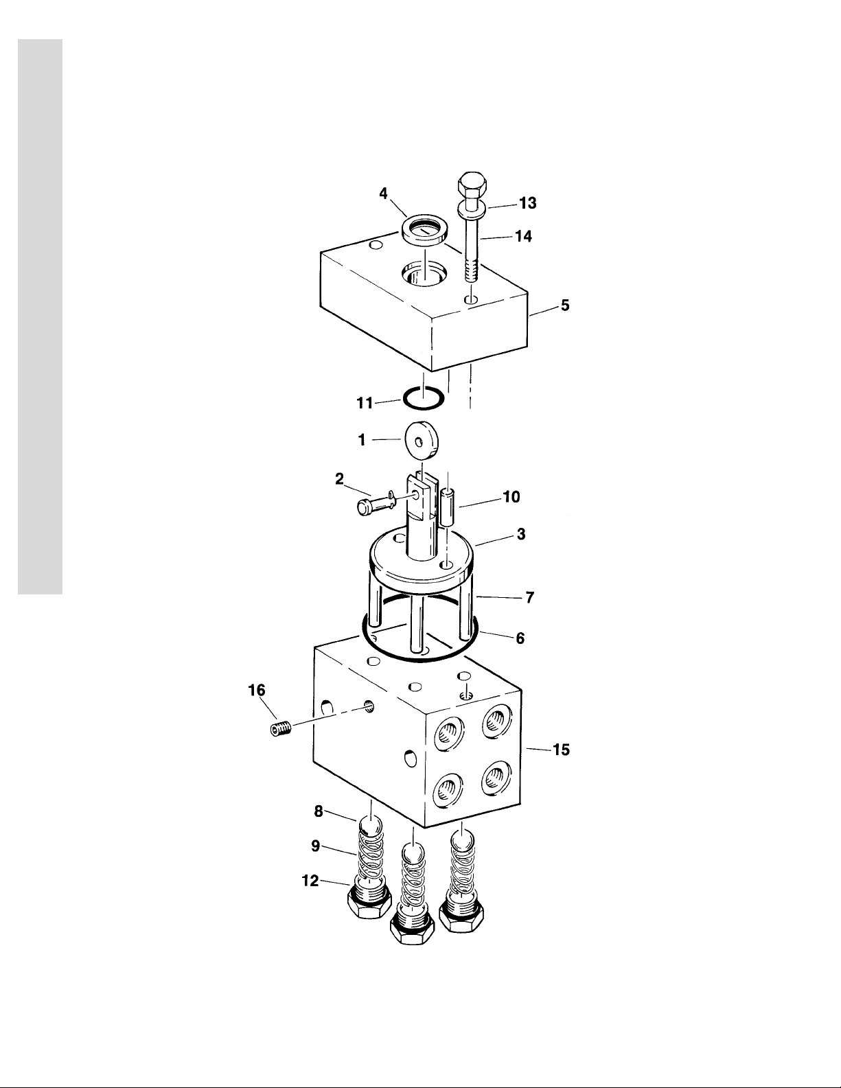
FIGURE 1-2. LOCKOUT VALVE ASSEMBLY
FIG & ITEM # PART NUMBER DESCRIPTION QTY. REV.
4640485 LOCKOUT VALVE ASSEMBLY Ref. B
1 3860037 Roller, Cam 1
2 3430407 Pin, Clevis 1/4" x 1" 1
3 3840833 Rod, Plunger 1
4 3960047 Seal, Rod 1
5 0560679 Block, Valve Top 1
6 3790231 O-Ring 1
7 3840854 Rod 4
8 0320008 Ball, Valve 4
9 4160078 Spring 4
10 3421284 Pin 2
11 3790116 O-Ring 1
12 2180658 Plug, Modified 4
13 0641518 Bolt 5/16"-18NC x 2 1/4" 2
14 4761500 Lockwasher 5/16" 2
15 0560467 Block, Valve 1
16 2200222 Plug 1/4" NPT 1
17 Not Used
18 3450203 Pin, Cotter 1
— — — — — — — — — —
0100011 Loctite (Not Shown) A/R
E
C
T
I
O
N
1
F
R
A
M
E
3120692 1-9
Page 16
S
SECTION 1 FRAME
E
C
T
I
O
N
1
F
R
A
M
E
FIGURE 1-3. TIRE AND WHEEL DRIVE INSTALLATIONS
1-10 3120692
Page 17

SECTION 1 FRAME
S
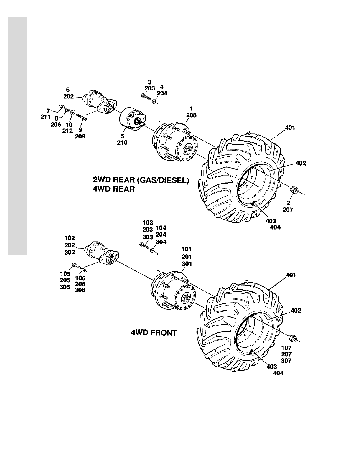
FIGURE 1-3. TIRE AND WHEEL DRIVE INSTALLATIONS
FIG & ITEM # PART NUMBER DESCRIPTION QTY. REV.
TIRE AND WHEEL DRIVE INSTALLATIONS Ref.
0252484 WHEEL DRIVE INSTALLATION - 2WD/2WS Ref. 3
1 2780169 Drive Hub Assembly (See Figure 1-6 for Breakdown) 2
2 3300012 Nut, Wheel 18
3 0642014 Bolt 5/8"-11NC x 1 3/4" 12
4 4762000 Lockwasher 5/8" 12
5 Drive Brake Assembly Options
(See Figure 1-5 for Breakdown):
0920084 Prior to S/N36660 2
0920110 S/N36660 to Present 2
6 3160158 Drive Motor Assembly
(See Figure 1-4 for Breakdown)
7 3311801 Nut 1/2"-13NC 4
8 4761800 Lockwasher 1/2" 4
9 4300092 Stud 1/2"-13NC x 5 1/2" 4
10 4711800 Flatwasher 1/2" Narrow 4
11 0100011 Loctite #242 (Not Shown) A/R
2
2
E
C
T
I
O
N
1
F
R
A
M
E
0251661 WHEEL DRIVE INSTALLATION - 2WD/4WS Ref. B
101 2780195 Drive Hub/Brake Assembly
(See Figure 1-7 for Breakdown)
102 3160158 Drive Motor Assembly
(See Figure 1-4 for Breakdown)
103 0642014 Bolt 5/8"-11NC x 1 3/4" 12
104 4762000 Lockwasher 5/8" 12
105 0641810 Bolt 1/2"-13NC x 1 1/4" 4
106 4761800 Lockwasher 1/2" 4
107 3300012 Nut, Wheel 18
0253545 WHEEL DRIVE INSTALLATION - 4WD/2WS FRONT
AND REAR (2MPH)
201 2780191 Drive Hub/Brake Assembly
(See Figure 1-7 for Breakdown)
202 3160158 Drive Motor Assembly
(See Figure 1-4 for Breakdown)
203 0642014 Bolt 5/8"-11NC x 1 7/8" 24
204 4762000 Lockwasher 5/8" 24
205 0641810 Bolt 1/2"-13NC x 1 1/4" 4
206 4761800 Lockwasher 1/2" 8
207 3300012 Nut, Wheel 36
208 2780167 Drive Hub Assembly (See Figure 1-6 for Breakdown) 2
209 4300092 Stud 1/2"-13NC x 5 1/2" 4
210 Drive Brake Assembly Options
(See Figure 1-5 for Breakdown):
0920084 Prior to S/N36660
0920110 S/N36660 to Present
Ref. 2
2
2
2
4
2
3120692 1-11
Page 18

S
SECTION 1 FRAME
E
C
T
I
O
N
1
F
R
A
M
E
FIGURE 1-3. TIRE AND WHEEL DRIVE INSTALLATIONS (CONTINUED)
FIG & ITEM # PART NUMBER DESCRIPTION QTY. REV.
211 3311801 Nut 1/2"-13NC 4
212 4711800 Flatwasher 1/2" 4
213 0100011 Loctite #242 (Not Shown) A/R
0255103 WHEEL DRIVE INSTALLATION - 4WD/2WS FRONT
AND REAR (4MPH)
201 2780193 Drive Hub/Brake Assembly
(See Figure 1-7 for Breakdown)
202 3160158 Drive Motor Assembly
(See Figure 1-4 for Breakdown)
203 0642014 Bolt 5/8"-11NC x 1 7/8" 24
204 4762000 Lockwasher 5/8" 24
205 0641810 Bolt 1/2"-13NC x 1 1/4" 4
206 4761800 Lockwasher 1/2" 8
207 3300012 Nut, Wheel 1/2"-20NC 36
208 2780175 Drive Hub Assembly (See Figure 1-6 for Breakdown) 2
209 4300092 Stud 1/2"-13NC x 5 1/2" 4
210 Drive Brake Assembly Options
(See Figure 1-5 for Breakdown):
0920084 Prior to S/N36660
0920110 S/N36660 to Present
211 3311801 Nut 1/2"-13NC 4
212 4711800 Flatwasher 1/2" 4
0100011 Loctite #242 (Not Shown) A/R
Ref. 2/B
2
4
2
0251660 WHEEL DRIVE INSTALLATION - 4WD/4WS FRONT
FRONT AND REAR (2MPH)
301 2780191 Drive Hub/Brake Assembly
(See Figure 1-7 for Breakdown)
302 3160158 Drive Motor Assembly
(See Figure 1-4 for Breakdown)
303 0642014 Bolt 5/8" - 11NC x 1 3/4" 24
304 4762000 Lockwasher 5/8" 24
305 0641810 Bolt 1/2"-13NC x 1 1/4" 8
306 4761800 Lockwasher 1/2" 8
307 3300012 Nut, Wheel 36
0250888 TIRE AND WHEEL INSTALLATION - STANDARD
31-15.5 x 15
0250886 Tire and Wheel Assembly - Left Side 2 B
0250887 Tire and Wheel Assembly - Right Side 2 B
401 4520123 Tire 4
402 4843635 Wheel 4
403 4640392 Stem, Valve 4
404 Not Required
Ref. B
4
4
Ref. —
1-12 3120692
Page 19

SECTION 1 FRAME
S
FIGURE 1-3. TIRE AND WHEEL DRIVE INSTALLATIONS (CONTINUED)
FIG & ITEM # PART NUMBER DESCRIPTION QTY. REV.
TIRE AND WHEEL INSTALLATION - OPTIONAL 12 x
16.5 LOADER LUG:
0251261 Prior to S/N44591 Ref. —
0258395 S/N44591 to Present Ref. 1
0251260 Tire & Wheel Assy - Left Side (Prior to S/N44591) 2 A
0258393 Tire & Wheel Assy - Left Side
(S/N44591 to Present)
0251259 Tire & Wheel Assy - Right Side (Prior to S/N44591) 2 —
0258394 Tire & Wheel Assy - Right Side
(S/N44591 to Present)
401 4520129 Tire 4
402 4860126 Wheel 4
403 4640113 Stem, Valve 4
404 1702698 Decal - Air Pressure (Not Shown)
(Prior to S/N44591 Only)
0258661 TIRE AND WHEEL INSTALLATION - OPTIONAL
31 x 15.50 x 15 (S/N 49250 TO PRESENT)
0258660 Tire & Wheel Assy - Left Side 2 1
0258659 Tire & Wheel Assy - Right Side 2 1
401 4520207 Tire 4
402 4843635 Wheel 4
403 4640392 Stem, Valve 4
404 Not Required
Ref.
21/A
21/A
4
Ref. 1
E
C
T
I
O
N
1
F
R
A
M
E
0255660 TIRE AND WHEEL INSTALLATION - OPTIONAL
FOAM FILLED 31 x 15.50 x 15
0255661 Tire and Wheel Assembly - Left Side 2 —
0255662 Tire and Wheel Assembly - Right Side 2 —
Note: Assemblies may require ballast/foam filling
to manufacturer’s specifications prior to installing on a machine. Refer to Operation & Safety or
Service & Maintenance Manuals. Purchase individual tire and/or rim only if able to foam fill tire &
wheel assembly, otherwise, purchase complete
assembly.
401 4520123 Tire - 31 x 15.50 x 15 4
0253089 TIRE AND WHEEL INSTALLATION - OPTIONAL
FOAM FILLED 12 x 16.5 LOADER LUG
0253088 Tire and Wheel Assembly - Left Side 2 —
0253087 Tire and Wheel Assembly - Right Side 2 —
Note: Assemblies may require ballast/foam filling
to manufacturer’s specifications prior to installing on a machine. Refer to Operation & Safety or
Service & Maintenance Manuals. Purchase individual tire and/or rim only if able to foam fill tire &
wheel assembly, otherwise, purchase complete
assembly.
401 4520129 Tire - 12 x 16.5 Loader Lug 4
Ref. —
Ref. —
3120692 1-13
Page 20

S
SECTION 1 FRAME
E
C
T
I
O
N
1
F
R
A
M
E
FIGURE 1-4. DRIVE MOTOR ASSEMBLY
1-14 3120692
Page 21

SECTION 1 FRAME
S
FIGURE 1-4. DRIVE MOTOR ASSEMBLY
FIG & ITEM # PART NUMBER DESCRIPTION QTY. REV.
3160158 DRIVE MOTOR ASSEMBLY Ref. A
1 Kit Ring, Retaining 1
2 Kit Seal, Shaft 1
3 7004906 Washer 1
4 Kit Ring, Retaining 2
5 7004907 Race, Thrust 2
6 7004908 Bearing, Thrust 1
7 7007874 Shaft, Splined 1
8 7004910 Bearing 1
9 7007875 Housing Assembly (Includes Item 8) 1
10 7007876 Insert, Camplate 1
11 7004917 Bearing 1
12 Kit O-Ring 1
13 7007878 Back Plate Assembly (Includes Item 11) 1
14 7007879 Bolt 6
15 7007880 Rotating Kit Assembly (Sold As An Assembly Only) 1
— — — — — — — — — —
2900714 Seal Kit (Includes Items 1,2,4 and 12) 1
E
C
T
I
O
N
1
F
R
A
M
E
3120692 1-15
Page 22

S
SECTION 1 FRAME
E
C
T
I
O
N
1
F
R
A
M
E
FIGURE 1-5. DRIVE BRAKE ASSEMBLY
1-16 3120692
Page 23

SECTION 1 FRAME
S
FIGURE 1-5. DRIVE BRAKE ASSEMBLY
FIG & ITEM # PART NUMBER DESCRIPTION QTY. REV.
DRIVE BRAKE ASSEMBLY OPTIONS: Ref.
0920084 Prior to S/N 36660 Ref. A
0920110 S/N 36660 to Present Ref. C
1 7011712 Shaft 1
2 Guide, Spring Options: 1
7011717 0920084 Brake (Prior to S/N36660)
7018606 0920110 Brake (S/N36660 to Present)
3 Spring Options: A/R
7007979 0920084 Brake (Inner) (Prior to S/N36660) 6
7007980 0920084 Brake (Outer) (Prior to S/N36660) 6
7007970 0920110 Brake (Red) (S/N36660 to Present) 6
7018602 0920110 Brake (Blue) (S/N36660 to Present) 3
4 Housing Options: 1
7011713 0920084 Brake (Prior to S/N36660)
7018605 0920110 Brake (S/N36660 to Present)
5 Return Plate and Separator Assembly Options: A/R
Kit Plate, Return - 0920084 Brake (Prior to S/N36660) 1
7011715 Separator Assy - 0920084 Brake
(Prior to S/N36660)
7011714 Pin 4
7007983 Separator 2
Kit Return Plate/Separator - 0920110 Brake
(S/N36660 to Present)
6KitRotor 2
7 Kit Stator 2
8 Kit Seal, Case 1
9 Bolt Options: 4
7007985 0920084 Brake (Prior to S/N36660)
7018607 0920110 Brake (S/N36660 to Present)
10 7007986 Cover 1
11 7007914 Screw, Bleeder (Prior to S/N37659) 1
7018609 Plug, Pipe (S/N37659 to Present) 1
12 7007987 Pin, Dowel 2
13 Kit Seal, Oil 1
14 7011716 Ring, Retainer 1
15 Kit Bearing 1
16 7007977 Ring, Retaining 1
17 Kit Ring, Back-up 1
18 Kit Ring, Back-up 1
19 Kit O-Ring 1
20 Kit O-Ring 1
21 Piston Options: 1
7007923 0920084 Brake (Prior to S/N36660)
7018603 0920110 Brake (S/N36660 to Present)
22 7007933 Gasket 2
23 Kit O-Ring 2
24 7007924 Plug, Pipe 1
— — — — — — — — — —
2
1
E
C
T
I
O
N
1
F
R
A
M
E
3120692 1-17
Page 24

S
SECTION 1 FRAME
E
C
T
I
O
N
1
F
R
A
M
E
FIGURE 1-5. DRIVE BRAKE ASSEMBLY (CONTINUED)
FIG & ITEM # PART NUMBER DESCRIPTION QTY. REV.
2900766 Seal Kit (Includes Items 8,13,17,18,19,20,22 and 23) 1
2900768 Bearing Kit (Includes Items 8,13,14,15,16,22 and 23) 1
Lining Kit Options (Includes Items 5,6,7,8,22 and 23): 1
2900767 0920084 Brake (Prior to S/N36660)
7018608 0920110 Brake (S/N36660 to Present)
1-18 3120692
Page 25

SECTION 1 FRAME
S
FIGURE 1-5. DRIVE BRAKE ASSEMBLY (CONTINUED)
FIG & ITEM # PART NUMBER DESCRIPTION QTY. REV.
E
C
T
I
O
N
1
F
R
A
M
E
3120692 1-19
Page 26
S
SECTION 1 FRAME
E
C
T
I
O
N
1
F
R
A
M
E
FIGURE 1-6. DRIVE HUB ASSEMBLIES
1-20 3120692
Page 27

SECTION 1 FRAME
S
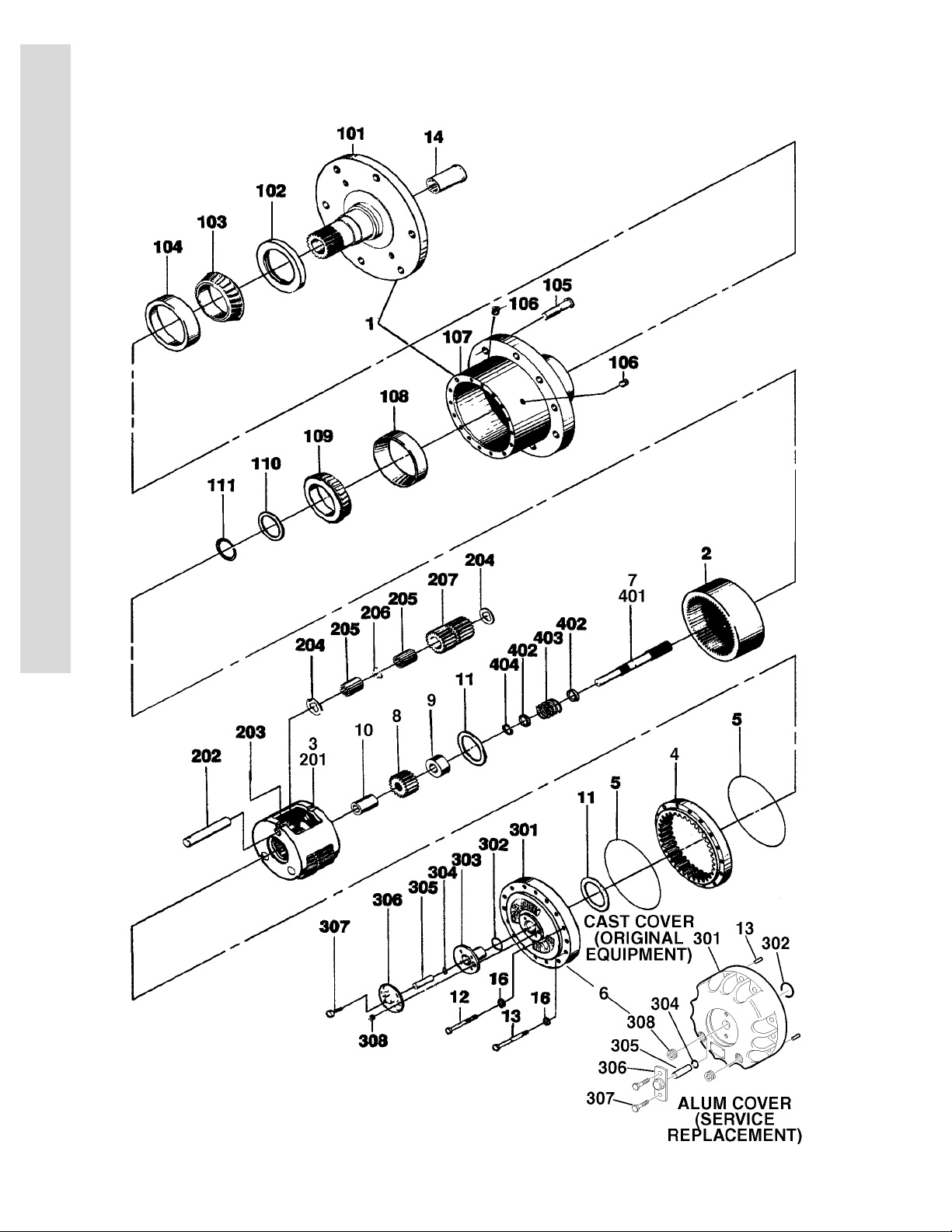
FIGURE 1-6. DRIVE HUB ASSEMBLIES
FIG & ITEM # PART NUMBER DESCRIPTION QTY. REV.
DRIVE HUB ASSEMBLIES OPTIONS: Ref.
2780169 2WD/2WS GAS/DIESEL (2MPH) Ref. —
2780167 4WD/2WS REAR DRIVE ONLY (2MPH) Ref. —
2780175 4WD/2WS REAR DRIVE ONLY (4MPH) Ref. —
1 7010428 Hub-Spindle Sub Assembly
(See Items 101-111 for Breakdown)
2 7000246 Gear, Internal 1
3 Carrier Assembly Options:
(See Items 201-207 for Breakdown)
7000247 2MPH Machines
7000202 4MPH Machines
4 Gear, Ring Options: 1
7007634 2780175 Hubs
7000248 2780167/2780169 Hubs
5 7000230 O-Ring 2
6 Cover Assembly (Includes Items 301-308) 1
7 Input Shaft Assembly Options: 1
7000250 2WD Machines
(See Items 401-404 for Breakdown)
7007650 4WD Machines
(See Items 401-404 for Breakdown)
8 Gear, Input Options: 1
7000251 2WD Machines
7007652 4WD Machines
9 Spacer, Thrust Options: 1
7000252 2WD Machines
7007653 4WD Machines
10 Spacer, Thrust Options: 1
Not Required 2WD Machines
7007654 4WD Machines
11 7000253 Washer, Thrust 2
7017096 Spacer (S/N 93772 to Present Only) 1
12 Bolt Options: 12
7000217 Prior to S/N 93772
7017067 S/N 93772 to Present
13 Hardware Options: 4
7000214 Bolt Used Prior to S/N 93772
7017080 Dowel Pin Used S/N 93772 to Present
14 7000206 Coupling 1
15 Not Used
16 7007603 Flatwasher 16
1
1
E
C
T
I
O
N
1
F
R
A
M
E
7010428 HUB - SPINDLE SUB-ASSEMBLY Ref.
101 7001997 Spindle 1
102 Kit Seal 1
103 Kit Cone, Bearing 1
104 Kit Cup, Bearing 1
105 7007697 Bolt, Wheel 9
3120692 1-21
Page 28

S
SECTION 1 FRAME
E
C
T
I
O
N
1
F
R
A
M
E
FIGURE 1-6. DRIVE HUB ASSEMBLIES (CONTINUED)
FIG & ITEM # PART NUMBER DESCRIPTION QTY. REV.
106 7000242 Plug, Pipe 2
107 7007601 Hub 1
108 7000257 Cup, Bearing 1
109 7000258 Cone, Bearing 1
110 Kit Spacer 1
111 Kit Ring, Retaining 1
CARRIER ASSEMBLY OPTIONS Ref.
7000202 2780175 Hubs Ref.
7000247 2780167/2780169 Hubs Ref.
201 7001931 Carrier 1
202 7001911 Shaft 3
203 7001913 Pin, Roll 3
204 7001985 Washer, Thrust 6
205 7001909 Roller, Needle 96
206 7000263 Spacer 3
207 Gear, Cluster Options: 3
7007643 2780175 Hubs
7001912 2780167/2780169 Hubs
COVER ASSEMBLY Ref.
See Kit Options Case Cover (Original Equipment) Ref.
See Kit Options Aluminum Cover (Service Replacement) Ref.
301 Cover Options: 1
Use 70001111 Case Cover (Original Equipment)
(was p/n 7000226)
Use 70001349 Aluminum Cover (Service Replacement)
(was p/n 7017091)
302 O-Ring Options: 1
Use 70001111 Case Cover (Original Equipment)
Use 70001349 Aluminum Cover (Service Replacement)
(was p/n 7017070)
303 Cap, Cover Options: 1
Use 70001111 Case Cover (Original Equipment)
Not Required Aluminum Cover (Service Replacement)
304 O-Ring Options: 1
Use 70001111 Case Cover (Original Equipment)
Use 70001349 Aluminum Cover (Service Replacement)
(was p/n 7017095)
305 Rod, Disconnect Options: 1
Use 70001111 Case Cover (Original Equipment)
Use 70001349 Aluminum Cover (Service Replacement)
(was p/n 7017092)
306 Cap, Disconnect 1
Use 70001111 Case Cover (Original Equipment)
Use 70001349 Aluminum Cover (Service Replacement)
(was p/n 7017093)
1-22 3120692
Page 29

SECTION 1 FRAME
S
FIGURE 1-6. DRIVE HUB ASSEMBLIES (CONTINUED)
FIG & ITEM # PART NUMBER DESCRIPTION QTY. REV.
307 Bolt Options: A/R
Use 70001111 Case Cover (Original Equipment)
(was p/n 7017093)
Use 70001349 Aluminum Cover (Service Replacement)
(was p/n 7000216)
308 Plug, Pipe Options: A/R
Use 70001111 Case Cover (Original Equipment)
(was p/n 7000243)
Use 70001349 Aluminum Cover (Service Replacement)
(was p/n 7017094)
INPUT SHAFT ASSEMBLY Ref.
7000250 2WD Ref.
7007650 4WD Ref.
401 Shaft Options: 1
7000260 2WD
7007651 4WD
402 7000263 Spacer 2
403 7000262 Spring 1
404 7000261 Ring, Retaining 1
— — — — — — — — — —
KIT OPTIONS: Ref.
7010429 Bearing Kit (Includes Items 103 and 104) 1
2900034 Seal Kit (Includes Items 5, 102, 110 and 111) 1
See Note Disconnect and Seal Kit Options (Includes Items 5,
102, 110, 111& 302-306) (was p/n 2900137)
Note: Use Cover Kit as Replacement. Ref.
Cover Kit Options: 1
Note: Kit Replaces Items 5, 11 (Spacer), 12, 13
(Dowel Pins), & 301-308.
Use 70001111 Cast Cover (was p/n 7001989 & p/n 7017099)
Use 70001349 Aluminum Cover (Service Replacement) (was p/n
7017090)
4
2
1
2
1
Ref.
E
C
T
I
O
N
1
F
R
A
M
E
3120692 1-23
Page 30

S
SECTION 1 FRAME
E
C
T
I
O
N
1
F
R
A
M
E
FIGURE 1-7. DRIVE HUB/BRAKE ASSEMBLIES
1-24 3120692
Page 31

SECTION 1 FRAME
S
FIGURE 1-7. DRIVE HUB/BRAKE ASSEMBLIES
FIG & ITEM # PART NUMBER DESCRIPTION QTY. REV.
DRIVE HUB/BRAKE ASSEMBLY OPTIONS: Ref.
2780195 2WD/4WS GAS/DIESEL MACHINES (2MPH) Ref. —
2780191 4WD GAS/DIESEL MACHINES (2MPH) Ref. —
2780193 4WD/2WS GAS/DIESEL MACHINES (4MPH) Ref. —
1 See Note Hub/Spindle/Brake Assembly (Note: Not sold as a
complete assembly) (See Items 101-113 for
Breakdown)
2 7007691 Gear, Internal 1
3 Carrier Assembly Options (See Items 201-207 for
Breakdown):
Not Available 2WD/4WS Machines
7000247 4WD with 2MPH Machines
See Note 4WD with 4MPH Machines (Note: Purchase
7000247 & install (3) 7007643 Cluster Gears to
make this carrier assembly)
4 7000248 Gear, Internal 1
5 Kit O-Ring 2
6 Cover Assembly
(See Items 301-308 for Breakdown)
7 In put Shaft Assembly Options
(See Items 401-404 for Breakdown):
7007650 4WD Machines
7000250 2WD/4WS Machines
8 Gear, Input Options: 1
7007652 4WD Machines
7000251 2WD/4WS Machines
9 Spacer, Input Options: 1
7007653 4WD Machines
7000252 2WD/4WS Machines
10 Spacer, Input Options: 1
7007654 4WD Machines
Not Required 2WD/4WS Machines
11 7000253 Washer, Thrust 2
7017096 Spacer (S/N 93772 to Present Only) 1
12 Bolt Options: 12
7000217 Prior to S/N 93772
7017067 S/N 93772 to Present
13 Hardware Options: 4
7000214 Bolt Used Prior to S/N 93772
7017080 Dowel Pin Used S/N 93772 to Present
14 to 15 Not Used
16 7007603 Flatwasher 16
17 7007692 Gasket 1
18 Not Used
19 7010470 Coupling 1
20 Not Used
21 7010459 Ring, Retainer 1
22 7001922 Washer, Thrust 1
1
1
1
1
E
C
T
I
O
N
1
F
R
A
M
E
3120692 1-25
Page 32

S
SECTION 1 FRAME
E
C
T
I
O
N
1
F
R
A
M
E
FIGURE 1-7. DRIVE HUB/BRAKE ASSEMBLIES (CONTINUED)
FIG & ITEM # PART NUMBER DESCRIPTION QTY. REV.
HUB/SPINDLE/BRAKE SUB-ASSEMBLY Ref.
101 Brake Assembly Options: 1
7010473 2WD/4WS Machines and 4WD Machines with I.D.
Plate (Item 309) Stamped July 1992 or Later (See
Items 601-604 for Breakdown)
7010469 4WD Machines with I.D. Plate (Item 309) Stamped
Prior to July 1992 (See Items 501-514 for
Breakdown)
102 Kit Seal, Lip 1
103 7007683 Cup, Bearing 1
104 7007684 Cone, Bearing 1
105 7007685 Cup, Bearing 1
106 7007686 Cone, Bearing 1
107 7007687 Housing 1
108 7007688 Flatwasher, Tanged 1
109 7007689 Flatwasher, Tanged 1
110 7007690 Nut, Bearing 1
111 7000242 Plug, Pipe 1/4" NPT 2
112 7000241 Stud, Wheel 9
113 7007617 Plug, Pipe 3/8" NPT (Magnetic) 2
7000247 CARRIER ASSEMBLY - 4WD(2MPH) MACHINES Ref.
NPN CARRIER ASSEMBLY - 4WD(4MPH) MACHINES Ref.
NPN CARRIER ASSEMBLY - 2WD/4WS MACHINES Ref.
201 7001931 Carrier 1
202 7001985 Washer, Thrust - Tanged 6
203 7001909 Bearing, Needle 96
204 7000263 Spacer, Thrust 3
205 7001911 Shaft, Planet 3
206 Gear, Cluster Options: 3
7001912 4WD with 2MPH Hub and 2WD/4WS
7007643 4WD with 4MPH Hub
207 Rollpin Options: 3
7001913 4WD Machines
7010474 2WD/4WS Machines
COVER ASSEMBLY Ref.
See Kit Options Cast Cover (Original Equipment) Ref.
See Kit Options Aluminum Cover (Service Replacement) Ref.
301 Cover Options: 1
Use 70001111 Cast Cover (Original Equipment)
(was p/n 7000226)
Use 70001349 Aluminum Cover (Service Replacement)
(was p/n 7017091)
302 O-Ring Options: 1
Use 70001111 Cast Cover (Original Equipment)
Use 70001349 Aluminum Cover (Service Replacement)
(was p/n 7017070)
1-26 3120692
Page 33

SECTION 1 FRAME
S
FIGURE 1-7. DRIVE HUB/BRAKE ASSEMBLIES (CONTINUED)
FIG & ITEM # PART NUMBER DESCRIPTION QTY. REV.
303 Cap, Cover 1
Use 70001111 Cast Cover (Original Equipment)
Not Required Aluminum Cover (Service Replacement)
304 O-Ring Options: 1
Use 70001111 Cast Cover (Original Equipment)
Use 70001349 Aluminum Cover (Service Replacement)
(was p/n 7017095)
305 Rod, Disconnect Options: 1
Use 70001111 Cast Cover (Original Equipment)
Use 70001349 Aluminum Cover (Service Replacement)
(was p/n 7017092)
306 Cap, Disconnect 1
Use 70001111 Cast Cover (Original Equipment)
Use 70001349 Aluminum Cover (Service Replacement)
(was p/n 7017093)
307 Bolt Options: A/R
Use 70001111 Cast Cover (Original Equipment)
(was p/n 7000220)
Use 70001349 Aluminum Cover (Service Replacement)
(was p/n 7000216)
308 Plug, Pipe Options: A/R
Use 70001111 Cast Cover (Original Equipment)
(was p/n 7000243)
Use 70001349 Aluminum Cover (Service Replacement)
(was p/n 7017094)
— — — — — — — — — — —
Cover Kit Options: 1
Note: Kit Replaces Items 5, 11 (Spacer), 12, 13
(Dowel Pins) & 301-308.
Use 70001111 Cast Cover (Original Equipment)
(was p/n 7001989 & p/n 7017099)
Use 70001349 Aluminum Cover (Service Replacement)
(was p/n 7017090)
4
2
1
2
Ref.
E
C
T
I
O
N
1
F
R
A
M
E
7007650 INPUT SHAFT ASSEMBLY - 4WD MACHINES Ref.
7000250 INPUT SHAFT ASSEMBLY - 2WD/4WS MACHINES Ref.
401 Shaft Options: 1
7007651 4WD Machines
7000260 2WD/4WS Machines
402 7000261 Ring, Retaining 1
403 7000262 Spring 1
404 7000263 Spacer, Thrust 2
7010469 BRAKE ASSEMBLY - 4WD MACHINES WITH I.D.
PLATE (ITEM 309) STAMPED JUNE 1992 OR
EARLIER
501 7014100 Spindle 1
502 7014101 Spacer 1
503 7014102 Disc, Stationary 7
3120692 1-27
Ref.
Page 34

S
SECTION 1 FRAME
E
C
T
I
O
N
1
F
R
A
M
E
FIGURE 1-7. DRIVE HUB/BRAKE ASSEMBLIES (CONTINUED)
FIG & ITEM # PART NUMBER DESCRIPTION QTY. REV.
504 7014103 Disc, Rotating 6
505 Kit Ring, Back-up 1
506 Kit O-Ring 1
507 Kit Ring, Back-up Ring 1
508 Kit O-Ring 1
509 7014108 Piston 1
510 7014109 Spring 6
7014110 Spring 2
511 Kit O-Ring 1
512 7014112 Cover 1
513 Not Available Bolt, Socket Head 3/8"-16NC x 1 1/4" 8
514 7014113 Expander 1
— — — — — — — — — —
2900816 Brake O-Ring Kit (Includes Items 505-508 and 511) 1
7010473 BRAKE ASSEMBLY - 2WD/4WS MACHINES AND
4WD MACHINES WITH I.D. PLATE (ITEM 309)
STAMPED JULY 1992 OR LATER
601 7010475 Brake Lining Kit 1
602 7010476 Brake O-Ring Kit 1
603 7010477 Brake Spring Repair Kit 1
604 7010478 Brake Piston Repair Kit 1
— — — — — — — — — —
70001940
Seal Kit - Hub (Includes Items 5,17,102, 109, 302
and 304)
Ref.
1
1-28 3120692
Page 35

SECTION 1 FRAME
S
FIGURE 1-7. DRIVE HUB/BRAKE ASSEMBLIES (CONTINUED)
FIG & ITEM # PART NUMBER DESCRIPTION QTY. REV.
E
C
T
I
O
N
1
F
R
A
M
E
3120692 1-29
Page 36

S
SECTION 1 FRAME
E
C
T
I
O
N
1
F
R
A
M
E
FIGURE 1-8. FRAME MOUNTED COMPONENTS INSTALLATION
1-30 3120692
Page 37

SECTION 1 FRAME
S
FIGURE 1-8. FRAME MOUNTED COMPONENTS INSTALLATION
FIG & ITEM # PART NUMBER DESCRIPTION QTY. REV.
FRAME MOUNTED COMPONENTS INSTALLATION Ref.
0253080 LIMIT SWITCH INSTALLATIONS
(PRIOR TO S/N34504)
1 0901855 Bracket, Mounting 1
2 4360300 Switch, Limit 1
3 4460049 Connector, Strain Relief 1
4 4751500 Flatwasher 5/16" 2
5 4761500 Lockwasher 5/16" 2
6 3311501 Nut 5/16"-18NC 2
7 3440413 Rollpin 1/8" x 13/16" 1
8 1100062 Cam (Hi-Drive Cutout) 1
9 0641612 Bolt 3/8"-16NC x 1 1/2" 2
10 4761600 Lockwasher 3/8" 2
11 Not Used
12 Not Used
13 4751600 Flatwasher 3/8" 2
14 Not Used
15 Not Used
16 3931032 Capscrew, Socket Head #10-24NC x 2" 4
17 4751000 Flatwasher #10 4
18 4761000 Lockwasher #10 4
19 3311001 Nut #10-24NC 4
20 Not Used
21 4300038 Stud (Welded on Part) 2
Ref. B
E
C
T
I
O
N
1
F
R
A
M
E
0256924 LIMIT SWITCH INSTALLATION
(S/N34504 TO PRESENT)
51 1100101 Cam (Hi-Drive Cutout) 1
52 0641408 Bolt 1/4"-20NC x 1" 2
53 4761400 Lockwasher 1/4" 2
54 0100019 Loctite (Not Shown) A/R
55 1320237 Clamp 1
56 3440410 Rollpin 1/8" x 5/8" 1
57 3931032 Screw, Machines #10-24NC x 2" 4
58 4751000 Flatwasher #10 4
59 4761000 Lockwasher #10 4
60 3311001 Nut #10-24NC 4
61 to 63 Not Used
64 4711400 Flatwasher 1/4" Narrow 2
65 0901855 Bracket, Mounting 1
66 3440420 Rollpin 1/8" x 1 1/4" 1
67 4360300 Switch, Limit 1
68 4460049 Connector, Strain Relief 1
69 4751500 Flatwasher 5/16" 2
70 4761500 Lockwasher 5/16" 2
71 3311501 Nut 5/16"-18NC 2
Ref. 2
3120692 1-31
Page 38

S
SECTION 1 FRAME
E
C
T
I
O
N
1
F
R
A
M
E
FIGURE 1-8. FRAME MOUNTED COMPONENTS INSTALLATION (CONTINUED)
FIG & ITEM # PART NUMBER DESCRIPTION QTY. REV.
72 4300038 Stud (Welded on Part) 2
LADDER INSTALLATION OPTIONS Ref.
0252739 25RTS With Fixed & Manual Extended Platform Ref. 5
0252740 25RTS With Traversing Platform Ref. 5
0252740 33RTS With Fixed & Manual Extended Platform Ref. 5
0252741 33RTS With Traversing Platform Ref. 5
0252741 40RTS With Fixed & Manual Extended Platform Ref. 5
0252742 40RTS With Traversing Platform Ref. 5
101 Ladder Weldment Options: 1
25RTS With Fixed & Manual Extended Platform
4844119 Prior to S/N 65031
4846041 S/N 65031 to Present
25RTS With Traversing Platform
4844120 Prior to S/N 65031
4846047 S/N 65031 to Present
33RTS With Fixed & Manual Extended Platform
4844120 Prior to S/N 65031
4846047 S/N 65031 to Present
33RTS With Traversing Platform
4844121 Prior to S/N 65031
4846047 S/N 65031 to Present
40RTS With Fixed & Manual Extended Platform
4844121 Prior to S/N 65031
Use 4846048 S/N 65031 to Present (was p/n 4846047)
40RTS With Traversing Platform
4844122 Prior to S/N 65031
4846048 S/N 65031 to Present
102 0641612 Bolt 3/8"-16Nc X 1 1/2" 2
103 4751600 Flatwasher 3/8" 8
104 4761600 Lockwasher 3/8" 4
105 3311605 Locknut 3/8"-16NC 4
106 0641610 Bolt 3/8"-16NC x 1 1/4" 2
107 3520071 Cap-Plug (Prior to S/N 65031) 2
OPTIONAL ALARM INSTALLATION Ref.
0253727 Descent Alarm Installation Ref. B
0253728 Motion Alarm Installation Ref. A
0253446 Travel Alarm Installation Ref. A
201 0140032 Alarm 1
202 4300038 Stud (Welded on Part) 2
203 4761500 Lockwasher 5/16" 2
204 3311501 Nut 5/16"-18NC 2
205 4751500 Flatwasher 5/16" 2
— — — — — — — — — —
3990010 Diode - 6 Amp (Not Shown - Located at Ground
Control)
3740049 Relay (Not Shown - Located at Ground Control) 1
1-32 3120692
A/R
Page 39

SECTION 1 FRAME
S
FIGURE 1-8. FRAME MOUNTED COMPONENTS INSTALLATION (CONTINUED)
FIG & ITEM # PART NUMBER DESCRIPTION QTY. REV.
1540002 Capacitor (Not Shown - Located at Ground Con-
trol)
AXLE COVERS INSTALLATION (2WS) (STANDARD
PARTS)
0253449 Diesel Machines Ref. —
0253448 Gas/Dual Fuel Machines Ref. —
301 Plate, Cover Options: 2
3536092 Diesel Machines
4844186 Gas/Dual Fuel Machines
302 0641510 Bolt 5/16"-18NC x 1 1/4" 8
303 4751500 Flatwasher 5/16" 16
304 4761500 Lockwasher 5/16" 8
305 3311501 Nut 5/16"-18NC 8
1
Ref.
E
C
T
I
O
N
1
F
R
A
M
E
3120692 1-33
Page 40

S
22
25
24
20
26
23
23
27
21
18
19
22
25
24
20
26
23
23
27
21
18
19
41
41
40
40
43
43
SECTION 1 FRAME
E
C
T
I
O
N
1
F
R
A
M
E
FIGURE 1-9. LEVELING JACK (WITH INTERLOCK) AND LIGHTS INSTALLATION (FRAME MOUNTED)
1-34 3120692
Page 41

SECTION 1 FRAME
S
FIGURE 1-9. LEVELING JACK (WITH INTERLOCK) AND LIGHTS INSTALLATION (FRAME
MOUNTED)
FIG & ITEM # PART NUMBER DESCRIPTION QTY. REV.
0254076 LEVELING JACKS INSTALLATION Ref. 9
1 4844554 Jack Cylinder Weldment 2
2 1682657 Jack Cylinder Assembly (See Section 5 for Breakdown) 4
3 0630327 U-Bolt 16
4 4751700 Flatwasher 7/16" 16
5 3311805 Locknut 1/2-13NC 16
6 0642016 Bolt 5/8"-11NC x 2" 8
7 4712000 Flatwasher 5/8" Narrow 32
8 4762000 Lockwasher 5/8" 16
9 3312001 Nut 5/8"-11NC 16
10 to 14 Not Used
15 1701785 Decal - Caution (Prior to S/N 71528) 4
16 to 17 Not Used
18 Connector, Strain Relief Options: 4
4460428 4360321 Switch
4460968 4360548 Switch
19 4360548 Switch, Limit (was p/n 4360321) 4
20 3911020 Screw, Machine #10-24NC x 1 1/4" 8
21 4751000 Flatwasher #10 8
22 3311005 Lock Nut #10-24NC 8
23 3440420 Rollpin 8
24 4740415 Flatwasher 4
25 4160116 Spring 4
26 3841221 Rod 4
27 1060341 Cable, Electrical - 16/2
28 to 39 Not Used
40 4420052 Tape, Safety
41 0902293 Bracket 4
42 4921586 Harness, Valve (Not Shown) 1
43 0642018 Bolt 5/8"-11NC x 2 1/4" 8
44ft/13.4m
8.5ft/2.6m
E
C
T
I
O
N
1
F
R
A
M
E
0253821 HEADLIGHTS & TAILLIGHTS INSTALLATION
(OPTIONAL)
See Section 10 for headlights/taillights at front & rear.Ref.
101 2920110 Headlight Assembly 2
7016628 Lamp, Replacement (1 Per Assembly) 2
102 0901927 Bracket - Headlight 2
103 4300032 Stud (Welded on Part) 4
104 4761400 Lockwasher 1/4" 4
105 4751400 Flatwasher 1/4" 4
106 3311401 Nut 1/4"-20NC 4
107 2920113 Taillight Assembly 2
Not Available Bulb, Replacement (1 Per Assy) (was p/n 7016626)
108 Not Used
109 0901928 Bracket - Taillight 2
110 0642012 Bolt 5/8"-11NC x 1 1/2" 2
111 4752000 Flatwasher 5/8" 2
3120692 1-35
Ref. 3
Page 42

S
SECTION 1 FRAME
E
C
T
I
O
N
1
F
R
A
M
E
FIGURE 1-9. LEVELING JACK (WITH INTERLOCK) AND LIGHTS INSTALLATION (FRAME
MOUNTED) (CONTINUED)
FIG & ITEM # PART NUMBER DESCRIPTION QTY. REV.
112 4762000 Lockwasher 5/8" 2
113 3312001 Nut 5/8"-20NC 2
114 3911040 Screw, Machine #10-24NC x 2 1/2" 4
115 4771000 Starwasher #10 4
116 4751000 Flatwasher #10 4
117 3311001 Nut #10-24NC 4
— — — — — — — — — —
1060341 Cable, Electrical - 16/2 30 ft./9m
3740049 Relay, Bosch (Not Shown - Located at Ground Control) 1
1-36 3120692
Page 43

SECTION 1 FRAME
S
FIGURE 1-9. LEVELING JACK (WITH INTERLOCK) AND LIGHTS INSTALLATION (FRAME
MOUNTED) (CONTINUED)
FIG & ITEM # PART NUMBER DESCRIPTION QTY. REV.
E
C
T
I
O
N
1
F
R
A
M
E
3120692 1-37
Page 44

S
SECTION 1 FRAME
E
C
T
I
O
N
1
F
R
A
M
E
FIGURE 1-10. LEVELING JACK (WITHOUT INTERLOCK) INSTALLATION
1-38 3120692
Page 45

SECTION 1 FRAME
S
FIGURE 1-10. LEVELING JACK (WITHOUT INTERLOCK) INSTALLATION
FIG & ITEM # PART NUMBER DESCRIPTION QTY. REV.
LEVELING JACKS INSTALLATION
0253678 (Prior to S/N 44592) Ref. B
0258290 (S/N 44592 to 101615) Ref. 4/B
0271581 (S/N 101615 to Present) Ref. 3/B
1 4844346 Jack Cylinder Weldment 2
2
Use 1684216 Prior to S/N 101615 (was p/n 1682720)
Use 1684217 S/N 101615 to Present (was p/n 1683966)
3 0641828 Bolt 1/2"-13NC x 3 1/2" 16
4Not Used
5 4761800 Lockwasher 1/2" 16
6 0642016 Bolt 5/8"-11NC x 2" (Prior to S/N 69771) 16
0642014 Bolt 5/8"-11NC x 1 3/4" (S/N 69771 to Present) 16
7 4712000 Flatwasher 5/8" Narrow 16
8 4762000 Lockwasher 5/8" (Prior to S/N 69771) 16
9 3312001 Nut 5/8"-11NC (Prior to S/N 69771) 16
3312005 Locknut 5/8"-11NC (S/N 69771 to Present) 16
10 4420052 Tape, Safety 8.5 ft.
11 4360548 Switch, Limit (was p/n 4360321) 8
12 3930820 Bolt, Socket Head #8-32NC 1 1/4" 16
13 3310805 Lock Nut #8-32NC 16
14 4750800 Flatwasher #8 16
15 Connector, Strain Relief Options: 8
4460428 4360321 Switch
4460968 4360548 Switch
16 Rod Options: 4
3841208 Prior to S/N 44592
3841326 S/N 44592 to Present
17 4160116 Spring 4
18 4740415 Washer, Special 4
19 3440420 Rollpin 8
20 4060848 Cover 4
21 0641406 Bolt 1/4"-20NC x 3/4" 16
22 4751400 Flatwasher 1/4" 16
23 4761400 Lockwasher 1/4" 16
24 Decal - Crushing Danger
1701785 (S/N45396 to 101615) 8
1703875 (S/N 101615 to Present 4
25 Decal, Tie Down Options: 4
Use 1703814 S/N45396 to S/N 71528 (was p/n 1702300)
1703814 S/N 71528 to Present
26 3520082 Plug, Cap (S/N 101615 to Present) 8
Jack Cylinder Assembly Options:
(See Section 5 for Breakdown)
4
E
C
T
I
O
N
1
F
R
A
M
E
3120692 1-39
Page 46

S
SECTION 1 FRAME
E
C
T
I
O
N
1
F
R
A
M
E
FIGURE 1-10. LEVELING JACK (WITHOUT INTERLOCK) INSTALLATION (CONTINUED)
FIG & ITEM # PART NUMBER DESCRIPTION QTY. REV.
LEVELING JACK COMPONENTS INSTALLATION Ref.
0255785 (Prior to S/N 101615 Ref. 5
0271583 (S/N 101615 to Present) Ref. 1
101-105 Not Used
106 Harness, Valve Options: (Not Shown) 1
4921586 (Prior to S/N 101615)
4922584 (S/N 101615 to Present)
1-40 3120692
Page 47

SECTION 1 FRAME
S
FIGURE 1-10. LEVELING JACK (WITHOUT INTERLOCK) INSTALLATION (CONTINUED)
FIG & ITEM # PART NUMBER DESCRIPTION QTY. REV.
E
C
T
I
O
N
1
F
R
A
M
E
3120692 1-41
Page 48

S
SECTION 1 FRAME
E
C
T
I
O
N
1
F
R
A
M
E
FIGURE 1-11. TOW PACKAGE INSTALLATION (OPTIONAL)
1-42 3120692
Page 49

SECTION 1 FRAME
S
FIGURE 1-11. TOW PACKAGE INSTALLATION (OPTIONAL)
FIG & ITEM # PART NUMBER DESCRIPTION QTY. REV.
TOW PACKAGE INSTALLATION
(STANDARD PARTS WHEN EQUIPPED)
0253079 Prior to S/N 98953 Ref. E
0271499 S/N 98953 to Present Ref. 1
1 0362080 Bar 1
2 3536156 Plate, Hitch Attach 1
3 4712600 Flatwasher 1" 4
4 2620037 Hitch, Tow 1
5 1660114 Coupling, Tie-Rod 2
6 3323002 Nut, Jam 1 1/4"-12NF 2
7 3841184 Tie-Rod 1
8 0642624 Bolt 1"-8NC x 3" 1
9 0642636 Bolt 1"-8NC x 4 1/2" 1
10 3422091 Pin 1
11 3841143 Keeper, Pin 1
12 2160002 Fitting, Grease 1
13 0900479 Bracket, Valve Mounting 1
14 4640261 Valve 1
15 0641507 Bolt 5/16"-18NC x 7/8" 2
16 4751500 Flatwasher 5/16" 3
17 4761600 Lockwasher 5/16" 3
18 3250872 Nameplate - Steer/Tow 1
19 3820001 Rivet 4
20 0641508 Bolt 5/16” - 18NC
Ref.
E
C
T
I
O
N
1
F
R
A
M
E
0253079 Tow Bar Installation (Prior to S/N 98953) Ref. E
101 to 119 Not Used
120 3420292 Pin, Quick Release 2
121 1260017 Chain 2
122 3536157 Plate 2
123 0361651 Bar (Prior to January 1994) 2
3537973 Plate (January 1994 to S/N 98953) 2
124 0362126 Tow Bar Assembly 1
124A 3420352 Pin, Tow 1
3420158 Hairpin 1
125 Not Used
126 Not Used
127 3420372 Hairpin (January 1994 to S/N 98953) 1
0271499 Tow Bar Installation (S/N 98953 to Present) Ref. 1
201 to 221 Not Used
222 0363019 Tow Bar Assembly 1
222A 3420372 Pin, Cotter 1
223 0902733 Bracket 1
224 0902734 Bracket 1
3120692 1-43
Page 50

S
SECTION 1 FRAME
E
C
T
I
O
N
1
F
R
A
M
E
FIGURE 1-11. TOW PACKAGE INSTALLATION (OPTIONAL) (CONTINUED)
FIG & ITEM # PART NUMBER DESCRIPTION QTY. REV.
225 0642018 Bolt 5/8” - 11NC 4
226 3312005 Nut 5/8” - 11NC 4
227 4752000 Flatwasher 5/8” 8
228 3340841 Pad (Not Shown) 1
1-44 3120692
Page 51

SECTION 2 GROUND COMPONENTS
TABLE OF CONTENTS
FIGURE DESCRIPTION
2-1 CONTROL VALVES AND TANKS INSTALLATIONS. . . . . . . . . . . . . . . . . . . . . . . . . . . . . . . . . . 2-2
2-2 CONTROL VALVE ASSEMBLY (Prior to S/N 26763) . . . . . . . . . . . . . . . . . . . . . . . . . . . . . . . . . 2-8
2-3 CONTROL VALVE ASSEMBLY (S/N 26763 to Present) . . . . . . . . . . . . . . . . . . . . . . . . . . . . . . . 2-12
2-4 CONTROL VALVE ASSEMBLY - FPS 4 STACK (Leveling Jacks Option). . . . . . . . . . . . . . . . . . 2-14
2-5 ENGINE INSTALLATION - FORD VSG-411 . . . . . . . . . . . . . . . . . . . . . . . . . . . . . . . . . . . . . . . . 2-16
2-6 ENGINE INSTALLATION - FORD VSG-413 . . . . . . . . . . . . . . . . . . . . . . . . . . . . . . . . . . . . . . . . 2-24
2-7 DUAL FUEL INSTALLATION (Ford Engine Option) . . . . . . . . . . . . . . . . . . . . . . . . . . . . . . . . . . 2-32
2-8 GENERATOR INSTALLATION (Ford Engine Option) . . . . . . . . . . . . . . . . . . . . . . . . . . . . . . . . . 2-36
2-9 ENGINE INSTALLATION - DEUTZ F2L1011 . . . . . . . . . . . . . . . . . . . . . . . . . . . . . . . . . . . . . . . 2-38
2-10 GENERATOR INSTALLATION (Deutz Engine Option) . . . . . . . . . . . . . . . . . . . . . . . . . . . . . . . . 2-44
2-11 PISTON PUMP ASSEMBLY - SUNSTRAND . . . . . . . . . . . . . . . . . . . . . . . . . . . . . . . . . . . . . . . 2-48
2-12 GEAR PUMP ASSEMBLY - JSB. . . . . . . . . . . . . . . . . . . . . . . . . . . . . . . . . . . . . . . . . . . . . . . . . 2-52
2-13 GROUND CONTROL BOX INSTALLATION . . . . . . . . . . . . . . . . . . . . . . . . . . . . . . . . . . . . . . . . 2-54
2-14 HOOD AND BEACON LIGHT INSTALLATION . . . . . . . . . . . . . . . . . . . . . . . . . . . . . . . . . . . . . . 2-58
S
E
C
T
I
O
N
2
G
R
O
U
N
D
C
O
M
P
O
N
E
N
T
S
3120692 2-1
Page 52

SECTION 2 GROUND COMPONENTS
OR
351
352
353
354
351A
351B
351C
S
E
C
T
I
O
N
2
G
R
O
U
N
D
FIGURE 2-1. CONTROL VALVES AND TANKS INSTALLATION
C
O
M
P
O
N
E
N
T
S
2-2 3120692
Page 53

SECTION 2 GROUND COMPONENTS
FIGURE 2-1. CONTROL VALVES AND TANKS INSTALLATION
FIG & ITEM # PART NUMBER DESCRIPTION QTY. REV.
CONTROL VALVES AND TANKS INSTALLATION
OPTIONS:
0253070 2WD/2WS Ref. 14
0253069 2WD/4WS Ref. 13
0253063 4WD/2WS Ref. 15
0253061 4WD/4WS Ref. 14
1 4640123 Solenoid Valve Assembly 1
7004368 Coil (Hydraforce Version) 1
7000558 Coil (FPS Version) 1
7012518 Seal Kit (Hydraforce Version) 1
7006075 Seal Kit (FPS Version) 1
2 0641420 Bolt 1/4”-20NC x 2 1/2” 1
3 4751400 Flatwasher 1/4” 1
4 3311405 Locknut 1/4”-20NC 1
5 1320202 Clamp, Hose A/R
6 Valve, Flow Divider Options: A/R
2WD Machines:
4640629 Valve (Prior to July 1993) 1
4640443 Valve (July 1993 to Present) 1
2900745 Seal Kit - 4640629 & 4640443 Valves 1
4WD/2WS Machines:
4640260 Valve (Prior to May 1993) 2
Not Available Cartridge (Vickers/Modular Control Version) 1
7009739 Seal Kit (Vickers/Modular Control Version) 1
7007321 Cartridge (Fluid Control Version) 1
Seal Kit (Fluid Control Version) (was p/n
Use 7007321
4640841 Valve (May 1993 to Present) 2
7007321 Cartridge - 4640481 Valve 1
4640260 Valve (Prior to July 1993) 2
Not Available Cartridge (Vickers/Modular Control Version) 1
7009739 Seal Kit (Vickers/Modular Control Version) 1
7007321 Cartridge (Fluid Control Version) 1
Use 7007321
4640847 Valve (Not Field Serviceable) (July 1993 to Pres-
7 4751500 Flatwasher 5/16” A/R
8 3311505 Locknut 5/16”-18NC A/R
9 4751600 Flatwasher 3/8” 16
10 3311605 Locknut 3/8”-16NC 6
7007323) (Note: No Longer Available for
Purchase)
4WD/4WS Machines:
Seal Kit (Fluid Control Version) (was p/n
7007323) (Note: No Longer Available for
Purchase)
ent)
Ref.
1
1
2
S
E
C
T
I
O
N
2
G
R
O
U
N
D
C
O
M
P
O
N
E
N
T
S
3120692 2-3
Page 54

S
E
C
T
I
O
N
2
G
R
O
U
N
D
C
O
M
P
O
N
E
N
T
S
SECTION 2 GROUND COMPONENTS
FIGURE 2-1. CONTROL VALVES AND TANKS INSTALLATION (CONTINUED)
FIG & ITEM # PART NUMBER DESCRIPTION QTY. REV.
11 Control Valve Assembly (Bang-Bang) Options: 1
2WS Machines:
4640578 Prior to July 1993 (See Figure 2-2 for
Breakdown)
4640844 July 1993 to S/N 26763 (See Figure 2-2 for
Breakdown)
4640943 S/N 26763 To Present (See Figure 2-3 for
Breakdown)
4WS Machines:
4640767 Prior to July 1993 (See Figure 2-2 for Break-
down)
4640845 July 1993 to S/N 26763 (See Figure 2-2 for
Breakdown)
4640944 S/N 26763 To Present (See Figure 2-3 for
Breakdown)
12 3100071 Manifold 1
13 0641506 Bolt 5/16"-18NC x 3/4" 2
14 4761500 Lockwasher 5/16" 2
15 2120109 Filter Assembly 1
2120110 Element - 25 Micron 1
2120129 Element - 10 Micron 1
16 0901853 Bracket, Valve Mounting 1
17 0641608 Bolt 3/8"-16NC x 1" A/R
18 Fuel Tank Options: 1
4400273 Prior to S/N 34451
4400402 S/N 34451 to S/N 80985
4400430 S/N 80985 to Present
19 Not Used
20 2200222 Plug, Pipe 1/4" NPT 3
21 Hydraulic Tank Assembly Options: (See Items 101-
112 for Breakdown)
4400282 Prior to S/N 82560
4400432 S/N 82560 to Present
22 1120361 Cap, Hydraulic Tank 1
23 Breather Options: 1
1340021 2WD/2WS, 2WD/4WS (Prior to S/N 63184)
1340062 2WD/2WS, 2WD/4WS, 4WD/4WS (S/N 63184 to
Present)
1340021 4WD/2WS (Prior to S/N 82560)
1340062 All Machines (S/N 82560 to Present)
24 4761600 Lockwasher 3/8" 8
25 0641511 Bolt 5/16"-18NC x 1 3/8" A/R
26 1320187 Clamp, 5/8" Twin Hole A/R
27 1320188 Bolt, Stacking 5
28 1320189 Lockwasher, Stacking 5
29 1320190 Plate, Clamp Cover A/R
30 0641514 Bolt 5/16"-18NC x 1 3/4" A/R
31 1320192 Clamp, 7/8" Twin Hole 5
32 1320193 Bolt, Stacking A/R
33 1320194 Lockwasher, Stacking A/R
34 1320195 Plate, Cover A/R
1
2-4 3120692
Page 55

SECTION 2 GROUND COMPONENTS
FIGURE 2-1. CONTROL VALVES AND TANKS INSTALLATION (CONTINUED)
FIG & ITEM # PART NUMBER DESCRIPTION QTY. REV.
35 Clamp Options: A/R
Not Required 2WD/2WS & 4WD/2WS 0
1320198 2WD/4WS 1
1320197 4WD/4WS 2
36 Clamp Options: A/R
Not Required 2WD/2WS, 4WD/2WS & 4WD/4WS 0
1320200 2WD/4WS 1
37 Bolt Options: A/R
Not Required 2WD/2WS, 4WD/2WS & 4WD/4WS 0
0641530 2WD/4WS (Bolt 5/16"-18NC x 3 3/4") 1
38 Link Options: 1
3010099 2WD/2WS, 2WD/4WS (July 1993 to S/N 63539)
3010099 4WD/2WS, 4WD/4WS (July 1993 to Present)
39 Clamp Options: A/R
Not Required 2WD/2WS & 2WD/4WS 0
1320197 4WD/2WS 2
1320198 4WD/4WS 1
40 Clamp Options: A/R
Not Required 2WD/2WS & 2WD/4WS 0
1320199 2WD/4WS & 4WD/4WS 1
41 4060807
Shield, Flex Trim (Not Shown)
(S/N 101993 to Present)
6.75ft/2.05m
S
E
C
T
I
O
N
2
G
R
O
U
N
D
HYDRAULIC TANK ASSEMBLY OPTIONS: Ref.
4400282 Prior to S/N 82560 Ref. C
4400432 S/N 82560 to Present Ref. A
101 Tank Options: 1
4400274 Prior to S/N 82560
4400431 S/N 82560 to Present
102 to 105 Not Used
106 2420115 Gauge, Sight 2
107 Plug Options: 1
2220240 Prior to S/N 82560
Not Required S/N 82560 to Present
108 Plug 1
2220242 Prior to S/N 82560
Not Required S/N 82560 to Present
109 Plug Options: 1
3520022 Prior to S/N 82560
2200233 S/N 82560 to Present
110 0100020 Sealant, Pipe A/R
111 2210066 Fitting 1
112 2180745 Fitting, Modified 1
C
O
M
P
O
N
E
N
T
S
3120692 2-5
Page 56

S
E
C
T
I
O
N
2
G
R
O
U
N
D
C
O
M
SECTION 2 GROUND COMPONENTS
FIGURE 2-1. CONTROL VALVES AND TANKS INSTALLATION (CONTINUED)
FIG & ITEM # PART NUMBER DESCRIPTION QTY. REV.
TILT INDICATOR INSTALLATION OPTIONS: Ref.
0253733 Standard Tilt Indicator Ref. 4
0254111 Tilt Indicator with Drive/Lift Lockout
(w/o Outriggers)
0254262 Tilt Indicator with Drive/Lift Lockout
(w/ Outriggers)
201 Sensor, Level Options: 1
4360348 Prior to S/N 71528
4360354 S/N 71528 to Present
202 0641405 Bolt 1/4"-20NC x 3/4" 2
203 Use 4751400 Lockwasher 1/4"(was p/n 4761400) 2
204 Use 3311405 Nut 1/4" -20NC (was p/n 3311401) 2
CONTROL VALVE INSTALLATION - HYDRAULIC
LEVELING JACKS OPTIONS:
0253195 (Prior to S/N 101615) Ref. 3
301 4640352 Control Valve Assembly - FPS 4 Stack
(See Figure 2-4 for Breakdown)
302 0641608 Bolt 3/8"-16NC x 1" 2
303 4761600 Lockwasher 3/8" 2
304 4711600 Flatwasher 3/8" 2
305 3311605 Locknut 3/8"-16NC 2
0271582 (S/N 101615 to Present) Ref. 1
Ref. 4
Ref. 4
Ref.
1
P
O
N
E
N
T
S
351 4641191 Control Valve Assembly 1
351A 7023937 Cartridge 1
2900756 Seal Kit 1
351B 7017454 Cartridge 4
7012903 Seal Kit 4
351C 7000645 Coil 8
352 4711600 Flatwasher 3/8” 2
353 3311605 Locknut 3/8” - 16NC 2
354 0641626 Bolt 3/8” - 16NC x 3 1/4” 2
FUEL CAP INSTALLATIONS Ref.
Prior To S/N 34451 Installation: Ref.
401 1120362 Cap, Fuel 1
402 Not Required
S/N 34451 to S/N 80985 Installations: Ref.
0257412 Standard Cap Installation Ref. 2
401 1120486 Cap, Fuel 1
402 2200108 Plug 1
0257413 Protectoseal Cap Installation Ref. 1
401 1120485 Cap, Protectoseal (Not Shown) 1
402 2420183 Gauge, Fuel (Not Shown) 1
2-6 3120692
Page 57

SECTION 2 GROUND COMPONENTS
FIGURE 2-1. CONTROL VALVES AND TANKS INSTALLATION (CONTINUED)
FIG & ITEM # PART NUMBER DESCRIPTION QTY. REV.
S/N 80985 to Present Installations: Ref.
Standard Cap Installation Ref. —
401 7020257 Cap, Fuel 1
7016649 Seal, Fuel Cap 1
402 Not Required
0270492 Protectoseal Cap Installation Ref. 1
401 1120485 Cap, Protectoseal (Not Shown) 1
402 Not Required
S
E
C
T
I
O
N
2
G
R
O
U
N
D
C
O
M
P
O
N
E
N
T
S
3120692 2-7
Page 58

SECTION 2 GROUND COMPONENTS
S
E
C
T
I
O
N
2
G
R
O
U
N
D
FIGURE 2-2. CONTROL VALVE ASSEMBLY (PRIOR TO S/N 26763)
C
O
M
P
O
N
E
N
T
S
2-8 3120692
Page 59

SECTION 2 GROUND COMPONENTS
FIGURE 2-2. CONTROL VALVE ASSEMBLY (PRIOR TO S/N 26763)
FIG & ITEM # PART NUMBER DESCRIPTION QTY. REV.
4640578 Bang-Bang Valve Assy (2WS) (Prior to July 1993) Ref. —
4640844 Bang-Bang Valve Assy (2WS) (July 1993 to
S/N 26763)
4640767 Bang-Bang Valve Assy (4WS) (Prior to July 1993)
(Not Shown)
4640845 Bang-Bang Valve Assy (4WS) (July 1993 to S/N
26763) (Not Shown)
1 7002304 Dump Section - Complete 1
Solenoid Assembly 1
2 7004823 Seat 1
Kit O-Ring 1
3 7002229 Ball 1
Guide Tube Assembly 1
4 7004822 Cone, Female 1
Kit O-Ring 1
5 7002346 Pin, Push 1
6 7004839 Plunger 1
7 7004838 Tube, Guide 1
8 7004841 Pin, Push 1
Kit O-Ring 1
9 7002340 Guide, External Push Pin 1
Kit O-Ring 1
10 7004834 Sleeve, Inner Flux 1
11 7002334 Spring 1
12 7004835 Sleeve, Outer Flux 1
13 7000417 Coil 1
14 7004836 Case, Solenoid 1
15 7002338 Plate, End 1
16 7004837 Screw 4
17 7002322 Seat 1
Kit O-Ring 1
Main Relief (Poppet) Valve 1
18 7002321 Case, Poppet 1
19 7002328 Spring 1
20 7002294 Poppet 1
21 7002320 Seat, Adjustable 1
Kit O-Ring 1
22 7002329 Spring 1
23 7002323 Plug 1
Kit O-Ring 1
24 7002326 Orifice 1
25 7002324 Plug 1
26 7004894 Working Section-Complete (Prior to July 1993) 1
7002444 Working Section-Complete (July 1993 to S/N 26763) 1
26A 7000468 Relief Valve Block Assembly (No Internal Compo-
nents Serviced Due to Various Vendors)
26B 7004859 Solenoid Assembly (Refer to Items 30-45 for Ser-
viced Parts)
27 7002315 Working Section - Complete 1
Ref. —
Ref. —
Ref. —
1
2
S
E
C
T
I
O
N
2
G
R
O
U
N
D
C
O
M
P
O
N
E
N
T
S
3120692 2-9
Page 60

S
E
C
T
I
O
N
2
G
R
O
U
N
D
C
O
M
P
SECTION 2 GROUND COMPONENTS
FIGURE 2-2. CONTROL VALVE ASSEMBLY (PRIOR TO S/N 26763) (CONTINUED)
FIG & ITEM # PART NUMBER DESCRIPTION QTY. REV.
28 7000468 Relief Valve Block Assembly (No Internal Compo-
nents Serviced Due to Various Vendors)
29 7004859 Solenoid Assembly 2
30 7003825 Washer, Hat (2 Per Section) 4
31 7002348 Spring (2 Per Section) 4
32 7004821 Guide Tube Assembly (2 Per Section) 4
33 7002345 Cone, Female (2 Per Section) 4
Kit O-Ring (2 Per Section) 4
34 7002346 Pin, Push (2 Per Section) 4
35 7002344 Plunger (2 Per Section) 4
36 7000470 Tube, Guide (2 Per Section) 4
37 7002341 Pin, Actuator (2 Per Section) 4
Kit Ring, Quad (2 Per Section) 4
38 7002340 Guide, External Push Pin (2 Per Section) 4
Kit O-Ring (2 Per Section) 4
39 7002333 Sleeve, Inner Flux (2 Per Section) 4
40 7002334 Spring (2 Per Section) 4
41 7002336 Sleeve, Outer Flux (2 Per Section) 4
42 7000418 Coil (2 Per Section) 4
43 7002335 Case, Solenoid (2 Per Section) 4
44 7002338 Plate, End (2 Per Section) 4
45 7002339 Screw (4 Per Section) 8
46 Not Used
47 2220237 Plug 1
48 2220238 Plug 1
7000414 Seal Kit - Working Section 2
7000413 Seal Kit - Dump Section 1
1
O
N
E
N
T
S
2-10 3120692
Page 61

SECTION 2 GROUND COMPONENTS
FIGURE 2-2. CONTROL VALVE ASSEMBLY (PRIOR TO S/N 26763) (CONTINUED)
FIG & ITEM # PART NUMBER DESCRIPTION QTY. REV.
S
E
C
T
I
O
N
2
G
R
O
U
N
D
C
O
M
P
O
N
E
N
T
S
3120692 2-11
Page 62

SECTION 2 GROUND COMPONENTS
S
E
C
T
I
O
N
2
G
R
O
U
N
D
FIGURE 2-3. CONTROL VALVE ASSEMBLY (S/N 26763 TO PRESENT)
C
O
M
P
O
N
E
N
T
S
2-12 3120692
Page 63

SECTION 2 GROUND COMPONENTS
FIGURE 2-3. CONTROL VALVE ASSEMBLY (S/N 26763 TO PRESENT)
FIG & ITEM # PART NUMBER DESCRIPTION QTY. REV.
4640943 BANG-BANG VALVE ASSEMBLY (2WS) Ref. —
4640944 BANG-BANG VALVE ASSEMBLY (4WS)
(NOT SHOWN)
1 7002447 Dump Section - Complete 1
2 7002448 Cartridge 1
7002449 Seal Kit - 7002448 Cartridge 1
3 7000645 Coil 1
4 7002451 Cartridge without Coil 1
7011118 Seal Kit - 7002451 Cartridge 1
5 7000448 O-Ring (Between Items #1 & #151) (Not Shown) 2
6 to 23 Not Used
24 7002444 Working Section-Complete 1
25 7011161 Relief Valve Block Assembly (No Internal Compo-
nents Serviced Due to Various Vendors)
26 7004859 Solenoid Assembly (Refer to Items 30-45 for Ser-
viced Parts)
27 7002315 Working Section - Complete 1
28 7000468 Relief Valve Block Assembly (No Internal Compo-
nents Serviced Due to Various Vendors)
29 7004859 Solenoid Assembly 2
30 7003825 Washer, Hat (2 Per Section) 4
31 7002348 Spring (2 Per Section) 4
32 7004821 Guide Tube Assembly (2 Per Section) 4
33 7002345 Cone, Female (2 Per Section) 4
Kit O-Ring (2 Per Section) 4
34 7002346 Pin, Push (2 Per Section) 4
35 7002344 Plunger (2 Per Section) 4
36 7000470 Tube, Guide (2 Per Section) 4
37 7002341 Pin, Actuator (2 Per Section) 4
Kit Ring, Quad (2 Per Section) 4
38 7002340 Guide, External Push Pin (2 Per Section) 4
Kit O-Ring (2 Per Section) 4
39 7002333 Sleeve, Inner Flux (2 Per Section) 4
40 7002334 Spring (2 Per Section) 4
41 7002336 Sleeve, Outer Flux (2 Per Section) 4
42 7000418 Coil (2 Per Section) 4
43 7002335 Case, Solenoid (2 Per Section) 4
44 7002338 Plate, End (2 Per Section) 4
45 7002339 Screw (4 Per Section) 8
46 Not Used
47 2220237 Plug 1
48 2220238 Plug 1
7000414 Seal Kit - Working Section 2
Ref. —
1
2
1
S
E
C
T
I
O
N
2
G
R
O
U
N
D
C
O
M
P
O
N
E
N
T
S
3120692 2-13
Page 64

SECTION 2 GROUND COMPONENTS
S
E
C
T
I
O
N
2
G
R
O
U
N
D
FIGURE 2-4. CONTROL VALVE ASSEMBLY - FPS 4 STACK (LEVELING JACKS OPTION)
C
O
M
P
O
N
E
N
T
S
2-14 3120692
Page 65

SECTION 2 GROUND COMPONENTS
FIGURE 2-4. CONTROL VALVE ASSEMBLY - FPS 4 STACK (LEVELING JACKS OPTION)
FIG & ITEM # PART NUMBER DESCRIPTION QTY. REV.
4640352 CONTROL VALVE ASSEMBLY - FPS 4 STACK
(LEVELING JACKS OPTION)
1 7000585 Nut 6
2 7000586 Washer 2
3 7006002 Rod, Tie 3
4 7006039 Bracket, Mounting 2
5 7000600 Section, Valve - Outlet 1
6 Kit O-Ring 5
7 7006041 Section, Valve - Complete 4
8 Spool (Not Sold Separately) (1 Per Section) 4
9 7006037 Retainer, Spring (2 Per Section) 8
10 7006036 Spring (2 Per Section) 8
11 7006034 Tube Assembly (2 Per Section) 8
12 Kit O-Ring (2 Per Section) 8
13 Kit O-Ring (2 Per Section) 8
14 4640049 Coil, Solenoid (2 Per Section) 8
15 Nameplate (Not Sold Separately) (2 Per Section) 8
16 7006033 Nut (2 Per Section) 8
17 Kit O-Ring (2 Per Section) 8
18 7006056 Section, Valve - Inlet 1
19 7006053 Cartridge, Relief 1
20 Not Used
21 Kit O-Ring (5 Per Section) 20
— — — — — — — — — —
7000549 Seal Kit - Single Section
(Includes Items 12,13,17 and 21)
7006062 Seal Kit - Standard Outlet (Includes Items 6) 1
Ref. C
5
S
E
C
T
I
O
N
2
G
R
O
U
N
D
C
O
M
P
3120692 2-15
O
N
E
N
T
S
Page 66

SECTION 2 GROUND COMPONENTS
S
E
C
T
I
O
N
2
G
R
O
U
N
D
FIGURE 2-5. ENGINE INSTALLATION - FORD VSG-411
C
O
M
P
O
N
E
N
T
S
2-16 3120692
Page 67

SECTION 2 GROUND COMPONENTS
FIGURE 2-5. ENGINE INSTALLATION - FORD VSG-411
FIG & ITEM # PART NUMBER DESCRIPTION QTY. REV.
ENGINE ASSEMBLY OPTIONS: Ref.
0253688 STANDARD GAS Ref. 15
0253690 DUAL FUEL Ref. 16
1 Engine Options: 1
2000118 Prior to January 1995
2000130 January 1995 to September 1995
2000133 September 1995 to S/N 30660
2000147 S/N 30660 to Present
2 Pump Options - Sunstrand
(See Figure 2-11 for Breakdown):
3600164 Prior to S/N 30660 (13 Teeth)
3600260 S/N 30660 to Present (15 Teeth)
3 3600206 Pump Assembly - Barnes
(See Figure 2-12 for Breakdown)
4 4843497 Bracket, Engine Mounting 1
5 3533445 Plate, Governor and Carburetor Mounting 1
6 Use 2902064 Controller, Governor (was p/n 1600117) 1
7 2500005 Governor, Precision 1
8 0641410 Bolt 1/4"-20NC x 1 1/4" 4
9 4761400 Lockwasher 1/4" 9
10 3311401 Nut 1/4"-20NC 9
11 0901419 Bracket, Controller 2
12 4751400 Flatwasher 1/4" 5
13 0641408 Bolt 1/4"-20NC x 1" 1
14 3911012 Screw, Machine #10-24NC x 3/4" 4
15 3311001 Nut #10-24NC 4
16 4751000 Flatwasher #10 6
17 4761000 Lockwasher #10 8
18 0100009 Adhesive A/R
19 3533291 Plate, Engine 1
20 0701014 Bolt, Metric M10 x 30MM 5
21 4832000 Lockwasher, Metric M10 5
22 3200202 Mount, Engine - Rear 2
23 3200201 Mount, Engine - Front 1
24 4740273 Washer, Snubbing 2
25 4751700 Flatwasher 7/16" 4
26 0641726 Bolt 7/16" - 14NC x 3 1/4" 2
27 3311705 Locknut 7/16" - 14NC 2
28 4740274 Washer, Snubbing 1
29 0641826 Bolt 1/2"-13NC x 3 1/4" 1
30 4751800 Flatwasher 1/2" 1
31 3311805 Locknut 1/2"-13NC 2
32 0641608 Bolt 3/8"-16NC x 1" 8
33 4761600 Lockwasher 3/8" 8
34 3311601 Nut 3/8"-16NC 8
35 1060221 Cable, Battery (Engine to Ground) 1
36 0641812 Bolt 1/2"-13NC x 1 1/2" 3
37 4761800 Lockwasher 1/2" 2
1
1
S
E
C
T
I
O
N
2
G
R
O
U
N
D
C
O
M
P
O
N
E
N
T
S
3120692 2-17
Page 68

S
E
C
T
I
O
N
2
G
R
O
U
N
D
C
O
M
P
O
N
E
N
T
S
SECTION 2 GROUND COMPONENTS
FIGURE 2-5. ENGINE INSTALLATION - FORD VSG-411 (CONTINUED)
FIG & ITEM # PART NUMBER DESCRIPTION QTY. REV.
38 to 39 Not Used
40 Bracket, Exhaust Support Options: 1
0901858 Standard Gas (Prior to S/N42208)
4845246 Standard Gas (S/N42208 to Present)
0901858 Dual Fuel (Prior to September 1995)
4845246 Dual Fuel (September 1995 to Present)
41 Adapter, Carburetor Options: 1
0080092 Standard Gas
See Note Dual Fuel (Note: See Figure 2-7 for Call-out)
42 3311405 Locknut 1/4"-20NC 1
43 Stud Options: 1
4300056 Standard Gas
See Note Dual Fuel (Note: See Figure 2-7 for Call-out)
44 3841049 Rod, Throttle 1
45 3321402 Nut, Jam 1/4"-28NF 2
46 1660157 Ball-joint 2
47 Not Used
48 2220273 Fitting, Reducer 1
49 2180360 Fitting, Tee 1
50 2420033 Sender, Oil Pressure 1
51 4360357 Switch, Pressure 1
52 2120135 Filter, Pressure 1
2120136 Element, Filter 1
53 1320014 Clamp, Hose 2
54 Adapter, Air Intake Options: 1
0080175 Standard Gas
See Note Dual Fuel (Note: See Figure 2-7 for Call-out)
55 3520046 Plug 1
56 2720341 Hose - Air Cleaner Outlet 1
57 1320058 Clamp, Hose 1
58 2180537 Fitting, Nipple 1
59 2200261 Fitting, Pipe Coupling (Prior to S/N42036 Only) 1
60 0901778 Bracket 1
61 3790152 O-Ring 1
62 0641610 Bolt 3/8"-16NC x 1 1/4" 2
63 4740185 Washer, Hardened 2
64 to 66 Not Used
67 3911014 Screw, Machine #10-24NC x 7/8" 2
68 Not Used
69 2720042 Hose
70 1320032 Clamp 2
71 4300090 Stud (Supplied with Engine) 2
72 3321501 Nut 5/16"-24NF 2
73 3536481 Plate, Engine Mounting 1
74 2420118 Sender, Temperature 1
75 0140001 Horn 1
76 2060019 Fan and Spacer Kit (Prior to S/N40684) 1
2901541 Fan and Spacer Kit (S/N40684 to Present) 1
77 Not Used
18in/46cm
2-18 3120692
Page 69

SECTION 2 GROUND COMPONENTS
FIGURE 2-5. ENGINE INSTALLATION - FORD VSG-411 (CONTINUED)
FIG & ITEM # PART NUMBER DESCRIPTION QTY. REV.
78 0641405 Bolt 1/4"-20NC x 5/8" 2
79 to 82 Not Used
83 0641632 Bolt 3/8"-16NC x 4" 2
84 3311605 Locknut 3/8"-16NC 2
85 4751600 Flatwasher 3/8" 4
86 0961378 Bushing 2
87 4460663 Housing, Terminal 1
88 4460660 Housing, Terminal 1
89 0100019 Loctite #271 (Not Shown) A/R
90 0100020 Sealant, Pipe (Not Shown) A/R
91 4031709 Capscrew, Metric M6-1.25 x 25mm 1
92 3290607 Locknut M6-1.25 1
93 7023676 Water Temperature Sender (Not Shown) 1
S
E
C
T
I
O
N
2
ENGINE INSTALLATION OPTIONS: Ref.
0253689/0254153
0253691/0254154
101 Not Used
102 4565830 Tube, Manifold 1
103 3220084 Muffler 1
104 1320026 U-Clamp 1
105 0901387 Bracket, Exhaust Hanger (Prior to S/N 34962) 1
0902382 Bracket, Exhaust Hanger (S/N 34962 to Present) 1
106 4565956 Tailpipe 1
107 1320058 Clamp, Hose 3
108 4843533 Tube, Air Intake 1
109 0080039 Elbow, Rubber 1
110 1340020 Air Cleaner Assembly 1
7004214 Element 1
111 0340002 Band, Air Cleaner Mounting 2
112 1120161 Cap, Air Inlet 1
113 0641406 Bolt 1/4"-20NC x 3/4" 4
114 4761400 Lockwasher 1/4" 4
115 3311401 Nut 1/4"-20NC 4
116 2220675 Fitting, 90° 1
117 4761600 Lockwasher 3/8" 9
118 3311601 Nut 3/8"-16NC 9
119 0641710 Bolt 7/16"-14NC x 1 1/4" 2
120 3533663 Plate, Radiator Mounting 1
121 0630403 Bolt, Carriage 7/16"-14NC x 1 1/2" 2
122 4751700 Flatwasher 7/16" 2
123 3311705 Locknut 7/16"-14NC 2
124 4761700 Lockwasher 7/16" 2
125 3311701 Nut 7/16"-14NC 2
126 3533664 Plate, Radiator Support 1
127 0630360 Bolt, Carriage 5/16"-18NC x 1 1/4" 1
128 4751500 Flatwasher 5/16" 5
129 3311501 Nut 5/16"-18NC 5
STANDARD GAS Ref. 1/1
DUAL FUEL Ref. 1/1
G
R
O
U
N
D
C
O
M
P
O
N
E
N
T
S
3120692 2-19
Page 70

S
E
C
T
I
O
N
2
G
R
O
U
N
D
C
O
M
P
SECTION 2 GROUND COMPONENTS
FIGURE 2-5. ENGINE INSTALLATION - FORD VSG-411 (CONTINUED)
FIG & ITEM # PART NUMBER DESCRIPTION QTY. REV.
130 0641508 Bolt 5/16"-18NC x 1" 1
131 4761500 Lockwasher 5/16" 2
132 0641610 Bolt 3/8"-16NC x 1 1/4" 6
133 4751600 Flatwasher 3/8" 15
134 4060713 Shield 1
135 3536151 Guard, Exhaust 1
136 1320022 Clamp 2
137 2720058 Hose, Fuel Line 6 ft./1.8m
138 0721004 Bolt #10-24NC x 1/2" 3
139 Not Used
140 0400003 Battery 1
141 3980003 Masonite 1
142 1060254 Cable, Battery (Battery + to Starter Solenoid) 1
143 3300029 Wingnut 3/8"-16NC 2
144 3536144 Cover, Battery 1
145 1060360 Cable, Battery (Battery Neg to Ground) 1
146 0630370 Rod, Tie-Down 2
147 0400002 Tie-Down, Battery 1
148 3620027 Radiator 1
149 Not Used
150 1320020 U-Clamp 1 1/2" 1
151 1320026 U-Clamp 1 3/4" 1
PUMP COUPLING INSTALLATION Ref.
0252808 2000118 Engine Assemblies (Prior to Sept. 1995) Ref. —
Supplied with
Engine
2000130/2000133/2000147 Engine Assemblies
(Sept. 1995 to Present)
Ref.
O
N
E
N
T
S
201 Pump Coupling Options: 1
1660207 13 Teeth Pump
7016661 15 Teeth Pump
202 0080163 Adapter, Pump Mounting 1
203 0700808 Bolt, Metric 8mm 1.25 x 16mm 6
204 4831900 Lockwasher, Metric 8mm 6
205 0641610 Bolt 3/8"-16NC x 1 1/4" 8
206 4761600 Lockwasher 3/8" 8
207 3020021 Grease, Coupling (Not Shown) A/R
Note: Coupling Spline must be greased with lithium
soap based grease prior to installation.
SPARE COMPONENTS Ref.
7014680 Spare Components Kit (Includes Carburetor, Fuel
Pump, Water Pump, Bosch Alternator, Starter & Ignition Control)
7014687 Spare Components Kit (Includes Carburetor, Fuel
Pump, Water Pump, Prestolite Alternator, Starter &
Ignition Control)
300 Use 7023670 Control, Ignition (was p/n 7019665) 1
Ref.
1
1
2-20 3120692
Page 71

SECTION 2 GROUND COMPONENTS
FIGURE 2-5. ENGINE INSTALLATION - FORD VSG-411 (CONTINUED)
FIG & ITEM # PART NUMBER DESCRIPTION QTY. REV.
301 7000892 Carburetor (Standard Gas) 1
7023471 Assembly, Float (Not Shown) 1
Use 7019933 Carburetor Rebuild Kit (was p/n 7000878) 1
70000163 Needle-Spring Load Fuel Valve 1
7024321 Gasket, Carburetor (Top) 1
7027607 Gasket, Carburetor (Bottom) 1
301A 7000894 Choke, Automatic 1
1140009
302 Alternator Options: 1
7000893 Bosch
7012653 Prestolite
7019670 Leese-Nuville
7019934 Belt, Alternator 1
7019935 Pulley, Alternator 1
303 7012577 Fitting, Vacuum Line 1
304 7012578 Vacuum Line Assembly 1
305 7000884 Fuel Shut-Off 1
306 7023668 Tune-Up Kit (Includes Oil and Fuel Filters, Spark
7014500 Filter, Oil - Case of 12 (Only 1 included in Kit) 1
7019949 Filter, Oil (Not Shown) 1
7019939 Filter, Fuel (Not Shown) 1
7019989 Kit, Spark Plug Wire/Clip on 1
307 7014681 Engine Kit (Includes Hoses, Gasket Set Belt and
7019941 Hose, Radiator (Upper) 1
7019943 Hose, Radiator (Lower) 1
7019942 Hose, Water Pump/Intake Inlet 1
308 7012564 Wiring Harness (Not Shown) 1
309 7019666 Pump, Fuel (Not Shown) 1
2120112 Separator, Fuel (Not Shown) 1
7025153 Gasket, Fuel Pump (Not Shown) 1
310 7019668 Starter 1
311 7019950 Thermostat 1
3960423 Gasket, Thermostat 1
312 7019667 Cap, Oil Filler (Not Shown) 1
313 7019936 Pulley, Crankshaft (Not Shown) 1
314 7019951 Pump, Water (Not Shown) 1
7019937 Pulley, Water Pump (Not Shown) 1
7019938 Outlet, Water (Not Shown) 1
7019945 Hose, Bypass (Not Shown) 1
315 7019944 Block Assembly, 11-Stud Terminal (Not Shown) 1
316 7019946 Flange, Exhaust Pipe (Not Shown) 1
7019947 Gasket, Exhaust Pipe Flange (Not Shown) 1
317 7019948 Manifold, Exhaust Outlet (Not Shown) 1
318 7019987 Coil, Ignition (Not Shown) 1
319 7019954 Harness, Ignition Module Patch (Not Shown) 1
320 7019959 Dipstick (Not Shown) 1
7019960 Tube, Dipstick (Not Shown) 1
Carburetor (LP Gas Only)
(Not Included in Components Kits)
Plugs and Wire Set)
Coil)
1
1
1
S
E
C
T
I
O
N
2
G
R
O
U
N
D
C
O
M
P
O
N
E
N
T
S
3120692 2-21
Page 72

S
E
C
T
I
O
N
2
G
SECTION 2 GROUND COMPONENTS
FIGURE 2-5. ENGINE INSTALLATION - FORD VSG-411 (CONTINUED)
FIG & ITEM # PART NUMBER DESCRIPTION QTY. REV.
321 70000929
322 7016602 Flywheel (Not Shown) (Engine 2000130 Only) 1
7022180 Gear, Ring (Not Shown) (Engine 2000130 Only) 1
7019919
323 7019917 Pump, Oil (Not Shown) 1
324 7020119
7020115 Kit, Coupling (Not Shown) (Engine 2000133 Only) 1
7020116 Coupling (Not Shown) (Engine 2000133 Only) 1
7016661 Coupling (Not Shown) (Engine 2000147 Only) 1
7020121
Sensor, Crankshaft (Not Shown) (Engines
2000130 & 2000147 Only)
Gear, Ring (Not Shown) (Engines 2000133 &
2000147 Only)
Housing, Bell (Not Shown) (Engines 2000133 &
2000147 Only)
Plate, Starter (Not Shown) (Engines 2000133 &
2000147 Only)
1
1
1
1
R
O
U
N
D
C
O
M
P
O
N
E
N
T
S
0251945 ENGINE DISTRESS SWITCH INSTALLATION
(OPTIONAL)
401 to 403 Not Used
404 2420131 Sender, Oil Pressure 1
0254736 HIGH TEMPERATURE WARNING INSTALLATION
(OPTIONAL)
501 4360157 Switch, Water Temperature 1
0080200 Adapter (Not Shown) 1
3960423 Gasket, Adapter (Not Shown) 1
0700819 Capscrew 8mm x 55mm 2
4831900 Lockwasher 8mm 2
0253875 SPARK ARRESTOR INSTALLATION (OPTIONAL) Ref. —
601 3220083 Arrestor, Spark (Includes Mounting Hardware) 1
0255037 GENERATOR INSTALLATION Ref. C
701 4360037 Sender, Oil 1
702 2180749 Fitting, 45° 1
703 2180360 Fitting, Tee 1
Ref. A
Ref. —
2-22 3120692
Page 73

SECTION 2 GROUND COMPONENTS
FIGURE 2-5. ENGINE INSTALLATION - FORD VSG-411 (CONTINUED)
FIG & ITEM # PART NUMBER DESCRIPTION QTY. REV.
S
E
C
T
I
O
N
2
G
R
O
U
N
D
C
O
M
P
O
N
E
N
T
S
3120692 2-23
Page 74

SECTION 2 GROUND COMPONENTS
S
E
C
T
I
O
N
2
G
R
O
U
N
D
FIGURE 2-6. ENGINE INSTALLATION - FORD VSG-413
C
O
M
P
O
N
E
N
T
S
2-24 3120692
Page 75

SECTION 2 GROUND COMPONENTS
FIGURE 2-6. ENGINE INSTALLATION - FORD VSG-413
FIG & ITEM # PART NUMBER DESCRIPTION QTY. REV.
ENGINE ASSEMBLY OPTIONS: Ref.
0257872 STANDARD GAS Ref. 9
0257911 DUAL FUEL Ref. 8
1 Engine Options: 1
2000155 Prior to S/N 89177
2000177 S/N 89177 to Present
2 3600260 Pump - Sunstrand (See Figure 2-11 for Breakdown) 1
3 3600206 Pump Assembly - Barnes
(See Figure 2-12 for Breakdown)
4 4843497 Bracket, Engine Mounting 1
5 3533445 Plate, Governor and Carburetor Mounting 1
6 Controller, Governor Options: 1
1600269 Prior to S/N 74487
1600325 S/N 74487 to Present
7 2500005 Governor, Precision 1
8 0641410 Bolt 1/4"-20NC x 1 1/4" 4
9 4761400 Lockwasher 1/4" 8
10 3311401 Nut 1/4"-20NC 8
11 0901419 Bracket, Controller 2
12 4751400 Flatwasher 1/4" 4
13 0641507 Bolt 5/16"-18NC x 1" 1
14 3911012 Screw, Machine #10-24NC x 3/4" 5
15 3311001 Nut #10-24NC 7
16 4751000 Flatwasher #10 8
17 4761000 Lockwasher #10 10
18 0100009 Adhesive A/R
19 3533291 Plate, Engine 1
20 0701012 Bolt, Metric M10 x 33MM 3
21 4832000 Lockwasher, Metric M10 5
22 3200202 Mount, Engine - Rear 2
23 3200201 Mount, Engine - Front 1
24 4740273 Washer, Snubbing 2
25 4751700 Flatwasher 7/16" 4
26 0641726 Bolt 7/16" - 14NC x 3 1/4" 2
27 3311705 Locknut 7/16" - 14NC 2
28 4740274 Washer, Snubbing 1
29 0641826 Bolt 1/2"-13NC x 3 1/4" 1
30 4751800 Flatwasher 1/2" 1
31 3311805 Locknut 1/2"-13NC 2
32 0641608 Bolt 3/8"-16NC x 1" 7
33 4761600 Lockwasher 3/8" 8
34 3311601 Nut 3/8"-16NC 8
35 1060221 Cable, Battery (Engine to Ground) 1
36 0641812 Bolt 1/2"-13NC x 1 1/2" 3
37 4761800 Lockwasher 1/2" 2
38 0700808 Bolt, Metric M8 x 16MM (S/N 61515 to Present) 1
39 4711500 Flatwasher 5/16" (S/N 61515 to Present) 1
40 4845246 Bracket, Exhaust Support 1
1
S
E
C
T
I
O
N
2
G
R
O
U
N
D
C
O
M
P
O
N
E
N
T
S
3120692 2-25
Page 76

S
E
C
T
I
O
N
2
G
R
O
U
N
D
C
O
M
P
O
N
E
N
T
S
SECTION 2 GROUND COMPONENTS
FIGURE 2-6. ENGINE INSTALLATION - FORD VSG-413 (CONTINUED)
FIG & ITEM # PART NUMBER DESCRIPTION QTY. REV.
41 Adapter, Carburetor Options: 1
0080092 Standard Gas
See Note Dual Fuel (Note: See Figure 2-7 for Call-out)
42 3311405 Locknut 1/4"-20NC 1
43 Stud Options: 1
4300056 Standard Gas
See Note Dual Fuel (Note: See Figure 2-7 for Call-out)
44 3841049 Rod, Throttle 1
45 3321402 Nut, Jam 1/4"-28NF 2
46 1660157 Ball-joint 2
47 4831900 Lockwasher Metric 8mm (S/N 61515 to Present) 1
48 2220273 Fitting, Reducer 1
49 2180360 Fitting, Tee 1
50 2420033 Sender, Oil Pressure 1
51 4360357 Switch, Pressure 1
52 2120135 Filter, Pressure 1
2120136 Element, Filter 1
53 1320014 Clamp, Hose 2
54 Adapter, Air Intake Options: 1
0080175 Standard Gas
See Note Dual Fuel (Note: See Figure 2-7 for Call-out)
55 3520046 Plug 1
56 2720341 Hose - Air Cleaner Outlet 1
57 1320058 Clamp, Hose 1
58 2180537 Fitting, Nipple 1
59 0701015 Bolt, Metric M10 x 35MM (S/N 61515 to Present) 2
60 0901778 Bracket 1
61 3790152 O-Ring 1
62 0641610 Bolt 3/8"-16NC x 1 1/4" 2
63 4740185 Washer, Hardened 2
64 to 66 Not Used
67 3911014 Screw, Machine #10-24NC x 7/8" 3
68 Not Used
69 2720042 Hose
70 1320032 Clamp 2
71 4300090 Stud (Supplied with Engine) 2
72 3321501 Nut 5/16"-24NF 3
73 3536481 Plate, Engine Mounting 1
74 2420118 Sender, Temperature 1
75 0140001 Horn 1
76 Fan and Spacer Kit Options: 1
Use 2060030 Standard Gas (was p/n 2060019)
(Prior to S/N 46254)
Use 2060030 Dual Fuel (was P/N2060016) (Prior to S/N 46254)
Use 2060030 All Machines (was p/n 2060029)
(S/N 46254 to S/N 75495)
2060030 All Machines (S/N 75495 to Present)
77 Not Used
78 0641405 Bolt 1/4"-20NC x 5/8" 2
79 to 80 Not Used
18in/46cm
2-26 3120692
Page 77

SECTION 2 GROUND COMPONENTS
FIGURE 2-6. ENGINE INSTALLATION - FORD VSG-413 (CONTINUED)
FIG & ITEM # PART NUMBER DESCRIPTION QTY. REV.
81 4761500 Lockwasher 5/16" 3
82 4751500 Flatwasher 5/16" 3
83 0641632 Bolt 3/8"-16NC x 4" 2
84 3311605 Locknut 3/8"-16NC 2
85 4751600 Flatwasher 3/8" 4
86 0961378 Bushing 2
87 4460663 Housing, Terminal 1
88 4460660 Housing, Terminal 1
89 0100019 Loctite #271 (Not Shown) A/R
90 0100020 Sealant, Pipe (Not Shown) A/R
91 3900275 Capscrew, Metric M6-1.25 x 25mm 1
92 3290607 Locknut M6-1.25 1
93 3911024 Screw #10-24NC x 1 1/2” (Not Shown) 2
94 0100048 Silicone (Not Shown) A/R
ENGINE INSTALLATION OPTIONS: Ref.
0257873 STANDARD GAS Ref. 5
0257912 DUAL FUEL Ref. 7
101 Not Used
102 Tube, Manifold Options: 1
4565830 Prior to S/N 62155
4567910 S/N 62155 to Present
103 3220084 Muffler 1
104 1320026 U-Clamp 1
105 0901387 Bracket, Exhaust Hanger (Prior to S/N 34962) 1
0902382 Bracket, Exhaust Hanger (S/N 34962 to Present) 1
106 4565956 Tailpipe 1
107 1320180 Clamp, Hose 3
108 4845649 Tube, Air Intake 1
109 0080039 Elbow, Rubber 1
110 1340020 Air Cleaner Assembly 1
7004214 Element 1
111 0340002 Band, Air Cleaner Mounting 2
112 1120161 Cap, Air Inlet 1
113 0641406 Bolt 1/4"-20NC x 3/4" 4
114 4751400 Lockwasher 1/4" 4
115 3311405 Locknut 1/4"-20NC 4
116 2220675 Fitting, 90° 1
117 4761600 Lockwasher 3/8" 9
118 3311601 Nut 3/8"-16NC 9
119 0641710 Bolt 7/16"-14NC x 1 1/4" 2
120 3533663 Plate, Radiator Mounting 1
121 0630403 Bolt, Carriage 7/16"-14NC x 1 1/2" 2
122 4751700 Flatwasher 7/16" 2
123 3311705 Locknut 7/16"-14NC 2
124 4761700 Lockwasher 7/16" 2
125 3311701 Nut 7/16"-14NC 2
126 3533664 Plate, Radiator Support 1
S
E
C
T
I
O
N
2
G
R
O
U
N
D
C
O
M
P
O
N
E
N
T
S
3120692 2-27
Page 78

S
E
C
T
I
O
N
2
G
R
O
U
N
D
C
O
M
P
O
N
E
N
T
SECTION 2 GROUND COMPONENTS
FIGURE 2-6. ENGINE INSTALLATION - FORD VSG-413 (CONTINUED)
FIG & ITEM # PART NUMBER DESCRIPTION QTY. REV.
127 0630360 Bolt, Carriage 5/16"-18NC x 1 1/4" 1
128 4711500 Flatwasher 5/16" Narrow 5
129 3311501 Nut 5/16"-18NC 5
130 0641508 Bolt 5/16"-18NC x 1" 1
131 4761500 Lockwasher 5/16" 2
132 0641610 Bolt 3/8"-16NC x 1 1/4" 6
133 4751600 Flatwasher 3/8" 15
134 4060713 Shield 1
135 3536151 Guard, Exhaust 1
136 1320022 Clamp 2
137 2720058 Hose, Fuel Line 6 ft./1.8m
138 3921008 Bolt #10-24NC x 1/2" 3
139 Not Used
140 0400075 Battery 1
141 3980007 Masonite 1
142 1060254 Cable, Battery (Battery + to Starter Solenoid) 1
143 3300029 Wingnut 3/8"-16NC 2
144 1670841 Cover, Battery 1
145 1060360 Cable, Battery (Battery Neg to Ground) 1
146 0630370 Rod, Tie-Down 2
147 0400174 Tie-Down, Battery 1
148 3620027 Radiator 1
149 Not Used
150 1320020 U-Clamp 1 1/2" 1
151 1320026 U-Clamp 1 3/4" 1
152 3252356 Nameplate - Important (LP Only) (S/N 71528 to Pres-
ent) (Not Shown Located Inside of Lower Access
Door)
153 1703162 Decal - Fan Blade (S/N 71528 to Present)
(Not Shown Located on Radiator Shield)
154 0840046 Boot, Battery (Positive) (Not Shown) 1
155 0840047 Boot, Battery (Negative) (Not Shown) 1
PUMP COUPLING INSTALLATION Ref.
1
2
S
201 7016661 Pump Coupling 1
202 0080163 Adapter, Pump Mounting 1
203 0700808 Bolt, Metric 8mm 1.25 x 16mm 6
204 4831900 Lockwasher, Metric 8mm 6
205 0641610 Bolt 3/8"-16NC x 1 1/4" 8
206 4761600 Lockwasher 3/8" 8
207 3020021 Grease, Coupling (Not Shown) A/R
Note: Coupling Spline must be greased with lithium
soap based grease prior to installation.
2-28 3120692
Ref.
Page 79

SECTION 2 GROUND COMPONENTS
FIGURE 2-6. ENGINE INSTALLATION - FORD VSG-413 (CONTINUED)
FIG & ITEM # PART NUMBER DESCRIPTION QTY. REV.
SPARE COMPONENTS Ref.
2000155 Prior to S/N 89177 Ref. B
2000177 S/N 89177 to Present Ref. A
300 Control, Ignition Options: 1
Use 7023670 Prior to S/N 89177 (was p/n 7019665)
7023650 S/N 89177 to Present
301 7000892 Carburetor (Standard Gas) 1
7024321 Gasket (Top) 1
7027607 Gasket, Carburetor (Bottom) 1
7019933 Carburetor Rebuild Kit 1
70000163 Needle-Spring Load Fuel Valve 1
7023471 Assembly, Float (Not Shown) 1
301A 7000894 Choke, Automatic 1
301 1140009 Carburetor (LP Gas Only)
(Not Included in Components Kits)
302 7019670 Alternator (Leese-Nuville) 1
7019934 Belt, Alternator 1
7019935 Pulley, Alternator 1
303 7012577 Fitting, Vacuum Line 1
304 7012578 Vacuum Line Assembly 1
305 7000884 Fuel Shut-Off 1
306 7022174 Filter, Fuel 1
307 Not Used
308 Wiring Harness Options (Not Shown): 1
7012564 Prior to S/N 89177
7023651 S/N 89177 to Present
309 7019666 Pump, Fuel (Not Shown) 1
2120112 Separator, Fuel (Not Shown) 1
7025153 Gasket, Fuel Pump (Not Shown) 1
310 7019668 Starter 1
311 Use 7021869
7014500 Filter, Oil (1 Dozen) 1
312 7019959 Dipstick (Not Shown) 1
7019960 Tube, Dipstick (Not Shown) 1
313 7019951 Pump, Water (Not Shown) 1
7019937 Pulley, Water Pump (Not Shown) 1
7019938 Outlet, Water (Not Shown) 1
7019945 Hose, Bypass (Not Shown) 1
7019942 Hose, Water Pump/Intake Inlet (Not Shown) 1
314 Plug Wire Kit Options: (Not Shown) 1
7019989 Through 1999
Use 7019989 2000 to Present (was p/n 7022176)
315 Coil, Ignition Options: (Not Shown) 1
Use 7019987 Through 1999 (was p/n 7019953)
7019998 2000 to Present
7019999 Bracket, Mounting 1
316 7019943 Hose, Lower Radiator 1
Filter, Oil (Not Shown) (was p/n 7022173 & p/n
7022147)
1
1
S
E
C
T
I
O
N
2
G
R
O
U
N
D
C
O
M
P
O
N
E
N
T
S
3120692 2-29
Page 80

S
E
C
T
I
O
N
2
G
R
O
U
N
D
SECTION 2 GROUND COMPONENTS
FIGURE 2-6. ENGINE INSTALLATION - FORD VSG-413 (CONTINUED)
FIG & ITEM # PART NUMBER DESCRIPTION QTY. REV.
317 7019950 Thermostat 1
3960423 Gasket, Thermostat 1
318 70000929 Sensor, Crankshaft (Not Shown) 1
319 7016602 Flywheel (Not Shown) 1
320 7019667 Cap, Oil Filler (Not Shown) 1
321 7019917 Pump, Oil (Not Shown) 1
322 7019919 Gear, Ring (Not Shown) 1
323 7019936 Pulley, Crankshaft (Not Shown) 1
324 7019941 Hose, Radiator (Upper) (Not Shown) 1
325 7019943 Hose, Radiator (Lower) (Not Shown) 1
326 7019944 Block Assembly, 11-Stud Terminal (Not Shown) 1
327 7019946 Flange, Exhaust Pipe (Not Shown) 1
7019947 Gasket, Exhaust Pipe Flange (Not Shown) 1
328 7019948 Manifold, Exhaust Outlet (Not Shown) 1
329 7019987 Coil, Ignition (Not Shown) 1
330 7019954 Harness, Ignition Module Patch (Not Shown) 1
331 7022100 Screw M5 x 16 (Not Shown) 4
332 7022172 Kit, Tune-Up (Not Shown) 1
0251945 ENGINE DISTRESS SWITCH INSTALLATION
(OPTIONAL)
Ref. B
C
O
M
P
O
N
E
N
T
S
401 to 403 Not Used
404 2420131 Sender, Oil Pressure 1
0254736 HIGH TEMPERATURE WARNING INSTALLATION
(OPTIONAL)
501 4360157 Switch, Water Temperature 1
0080200 Adapter (Not Shown) 1
3960423 Gasket, Adapter (Not Shown) 1
0700819 Capscrew 8mm x 55mm 2
4831900 Lockwasher 8mm 2
0253875 SPARK ARRESTOR INSTALLATION (OPTIONAL) Ref. —
601 3220083 Arrestor, Spark (Includes Mounting Hardware) 1
0255037 GENERATOR INSTALLATION (OPTIONAL) Ref. 3/B
701 4360037 Sender, Oil 1
702 2180749 Fitting, 45° 1
703 2180360 Fitting, Tee 1
Ref. —
2-30 3120692
Page 81

SECTION 2 GROUND COMPONENTS
FIGURE 2-6. ENGINE INSTALLATION - FORD VSG-413 (CONTINUED)
FIG & ITEM # PART NUMBER DESCRIPTION QTY. REV.
S
E
C
T
I
O
N
2
G
R
O
U
N
D
C
O
M
P
O
N
E
N
T
S
3120692 2-31
Page 82

SECTION 2 GROUND COMPONENTS
S
E
C
T
I
O
N
2
G
R
O
U
N
D
FIGURE 2-7. DUAL FUEL COMPONENTS INSTALLATION (FORD ENGINE OPTION)
C
O
M
P
O
N
E
N
T
S
2-32 3120692
Page 83

SECTION 2 GROUND COMPONENTS
FIGURE 2-7. DUAL FUEL COMPONENTS INSTALLATION (FORD ENGINE OPTION)
FIG & ITEM # PART NUMBER DESCRIPTION QTY. REV.
0250790 DUAL FUEL INSTALLATION Ref. 12
1 3720011 Regulator, LPG 1
7017516 Rebuilt Kit 1
2 2220364 Fitting, Adapter 2
3 2180535 Fitting, Barbed 2
4 2220648 Fitting, 90° 1
5 2120077 Filter-Lock 1
6 2220003 Fitting, Swivel 1
7 2220675 Fitting, 90° 1
8 2720112 Hose, LP A/R
9 2720042 Hose, Heater
10 2720118 Hose, LP (48 in./1.22m Length) (Prior to S/N 27430) 1
2720437 Hose, LP (52 in./1.32m Length) (S/N 27430 to Present) 1
11 1320032 Clamp 4
12 2180104 Fitting, Nipple 1
13 2180360 Fitting, Tee 1
14 4360188 Switch, Vacuum 1
15 2180536 Fitting, Barbed 1
16 2180623 Fitting, Tee 1
17 0641405 Bolt 1/4"-20NC x 5/8" 2
18 4761400 Lockwasher 1/4" 2
19 2180387 Fitting, Tank Connector 1
20 to 22 Not Used
23 0080167 Adapter, Air Intake 1
24 0080092 Adapter, Carburetor 1
25 3840979 Rod 1
26 Not Used
27 1700818 Decal - Liquid LPG 1
28 to 30 Not Used
31 4640391 Valve, Gasoline 1
32 1320095 Clamp, Support 1
33 2220805 Fitting, Straight 3
34 1320022 Clamp 2
35 2220290 Fitting, Tee 1
36 2180389 Fitting, Pressure Relief 1
37 Tank, LP Options: (Optional - Not Supplied with
Installation)
4400040 Aluminum - 33.5 Lbs. Tank (Prior to S/N 60261)
4400281 Aluminum - 33.5 Lbs. Tank (S/N 60261 to Present)
4400421 Steel - 33.5 Lbs. Tank (S/N 60261 to Present)
4400275 Aluminum - 43.5 Lbs. Tank
4400420 Steel - 43.5 Lbs. Tank (S/N 60261 to Present)
28in/71m
2
S
E
C
T
I
O
N
2
G
R
O
U
N
D
C
O
M
P
O
N
E
N
T
S
0253447 LP TANK BRACKETS INSTALLATION Ref. 3
101 4844185 Support, Tank Bracket 2
102 0641522 Bolt 5/16"-18NC x 2 3/4" 2
103 4761500 Lockwasher 5/16" 2
3120692 2-33
Page 84

S
E
C
T
I
O
N
2
G
R
O
U
N
SECTION 2 GROUND COMPONENTS
FIGURE 2-7. DUAL FUEL COMPONENTS INSTALLATION (FORD ENGINE OPTION) (CONTINUED)
FIG & ITEM # PART NUMBER DESCRIPTION QTY. REV.
104 3311501 Nut 5/16"-18NC 2
105 0641610 Bolt 3/8"-16NC x 1 1/4" 8
106 4751600 Flatwasher 3/8" 8
107 4761600 Lockwasher 3/8" 8
108 3311601 Nut 3/8"-16NC
109 1320023 Clamp, LP Tank 2
D
C
O
M
P
O
N
E
N
T
S
2-34 3120692
Page 85

SECTION 2 GROUND COMPONENTS
FIGURE 2-7. DUAL FUEL COMPONENTS INSTALLATION (FORD ENGINE OPTION) (CONTINUED)
FIG & ITEM # PART NUMBER DESCRIPTION QTY. REV.
S
E
C
T
I
O
N
2
G
R
O
U
N
D
C
O
M
P
O
N
E
N
T
S
3120692 2-35
Page 86

SECTION 2 GROUND COMPONENTS
S
E
C
T
I
O
N
2
G
R
O
U
N
D
FIGURE 2-8. GENERATOR INSTALLATION (FORD ENGINE OPTION)
C
O
M
P
O
N
E
N
T
S
2-36 3120692
Page 87

SECTION 2 GROUND COMPONENTS
FIGURE 2-8. GENERATOR INSTALLATION (FORD ENGINE OPTION)
FIG & ITEM # PART NUMBER DESCRIPTION QTY. REV.
GENERATOR INSTALLATION
(FORD ENGINE OPTION)
0250444 Prior to August 1994 Ref. D
0255037 August 1994 to Present Ref. 3/B
1Not Used
2 2460011 Generator Assembly with Control Box 1
2A 7012558 Generator Assembly Only 1
7020108 Brush 4
7020109 Holder, Brush 4
7012513 Caps, Brush Holder 4
7012514 Fan 1
7020193 Cord, Power 1
7026199 Armature 1
7020110 End Bell, Front 1
7020111 End Bell, Rear 1
7020190 Bearing 2
2B 7003657 Control Box Assembly 1
Note: Replacement 110V Control Box comes
with 2 std Receptacles p/n 4460190. Optional
Industrial Twist Lock Receptacles p/n 4460027
must be ordered separately.
4360542 Breaker, Circuit 1
4460190 Receptacle 2
2920162 Lamp 1
7020191 Switch, Toggle 1
3520028 Plug, Hole 1
2C 2420203 Voltmeter 1
2D 3580134 Pulley 1
3 2860012 Keystock 1
4 0901650 Bracket, Generator Mounting 1
5 4340569 Support, Adjustable 1
6 0480057 V-Belt 1
7Not Used
8 4761600 Lockwasher 3/8" 4
9 3311601 Nut 3/8" - 16NC 2
10 0641511 Bolt 5/16"-18NC x 1 3/8" 1
11 4751500 Flatwasher 5/16" 2
12 4761500 Lockwasher 5/16" 2
13 0961247 Bushing 1
14 0641507 Bolt 5/16"-18NC 2
15 0901609 Bracket, Box Mounting 1
16 3911004 Screw, Machine #10-24NC x 1/2" 2
17 3311001 Nut #10-24NC 2
18 4761000 Lockwasher #10 2
19 Not Used
20 0681610 Bolt 3/8"-16NC x 1 1/4" (Grade 8) 2
21 4751600 Flatwasher 3/8" 2
22 to 23 Not Used
24 3311501 Nut 5/16"-16NC 2
Ref.
S
E
C
T
I
O
N
2
G
R
O
U
N
D
C
O
M
P
O
N
E
N
T
S
3120692 2-37
Page 88

SECTION 2 GROUND COMPONENTS
S
E
C
T
I
O
N
2
G
R
O
U
N
D
FIGURE 2-9. ENGINE INSTALLATION - DEUTZ F2L1011
C
O
M
P
O
N
E
N
T
S
2-38 3120692
Page 89

SECTION 2 GROUND COMPONENTS
FIGURE 2-9. ENGINE INSTALLATION - DEUTZ F2L1011
FIG & ITEM # PART NUMBER DESCRIPTION QTY. REV.
0253361 ENGINE INSTALLATION - DEUTZ F2L1011 Ref. 18
1 Engine - Deutz F2L1011 1
2000106 Prior to August 1995
2000137 August 1995 to Present
2 4843934 Tray, Engine Mounting 1
3Not Used
4 Pump Assembly - Sunstrand
(See Figure 2-11 for Breakdown)
3600164 13 Tooth Spline (Prior to S/N 30660)
3600260 15 Tooth Spline (S/N 30660 to Present)
5 0361817 Spacer, Engine Mounting 4
6 0080177 Adapter, Air Intake 1
7 Adapter, Throttle 1
0080172 Prior to August 1995
4460302 August 1995 to Present
8 3450202 Pin, Cotter 1/16" x 1/2" 1
9 3951003 Setscrew #10-24NC x 3/8" (Prior to August 1995) 1
0902244 Bracket, Throttle (August 1995 to Present) 1
10 0641840 Bolt 1/2"-13NC x 5" 4
11 3311805 Locknut 1/2"-13NC 4
12 4751800 Flatwasher 1/2" 4
13 0641406 Bolt 1/4"-20NC x 3/4" 4
14 4711400 Flatwasher 1/4" 24
15 3311405 Locknut 1/4"-20NC 4
16 0641512 Bolt 3
17 Cable, Battery Options: 1
1060406 Prior to S/N 70832
1060254 S/N 70832 to Present
18 1060093 Cable, Battery 1
19 0140001 Horn 1
20 0641610 Bolt 3/8"-16NC x 1 1/4" 2
21 4751600 Flatwasher 3/8" 18
22 0060023 Actuator, Throttle 1
7008828 Cable, Throttle 1
23 0901817 Bracket, Fuel Filter 1
24 0701010 Bolt, Metric M10 x 20mm 4
25 4832000 Lockwasher 10m 4
26 0641508 Bolt 5/16"-18NC x 1" 2
27 3311501 Nut 5/16"-18NC 5
28 4761500 Lockwasher 5/16" 5
29 4751600 Lockwasher 3/8" 12
30 0400003 Battery (Prior to S/N44593) 1
0400075 Battery (S/N44593 to Present) 1
31 0400002 Tie-Down, Battery (Prior to S/N44593) 1
0400174 Tie-Down, Battery (S/N44593to Present) 1
32 3980003 Seat, Battery (Prior to S/N44593) 1
3980007 Seat, Battery (S/N44593to Present) 1
33 0630370 Rod, Tie-Down 2
1
S
E
C
T
I
O
N
2
G
R
O
U
N
D
C
O
M
P
O
N
E
N
T
S
3120692 2-39
Page 90

S
E
C
T
I
O
N
2
G
R
O
U
N
D
C
O
M
P
O
N
E
N
T
S
SECTION 2 GROUND COMPONENTS
FIGURE 2-9. ENGINE INSTALLATION - DEUTZ F2L1011 (CONTINUED)
FIG & ITEM # PART NUMBER DESCRIPTION QTY. REV.
34 3300029 Wingnut 3/8"-16NC 2
35 1060360 Cable, Battery 1
36 4740195 Washer, Hardened 2
37 3311601 Nut 3/8"-16NC 6
38 0641612 Bolt 3/8"-16NC x 1 1/2" 6
39 4843513 Air Intake Weldment 1
40 2180730 Fitting, Adapter 1
41 2420110 Sender, Oil Pressure 1
42 3960407 Gasket 1
43 1340020 Air Cleaner Assembly 1
7004214 Element, Air Cleaner 1
44 0340002 Band, Mounting - Air Cleaner 2
45 1320180 Clamp, Hose 6
46 2720351 Hose
47 4565347 Tube, Air Cleaner 1
48 0080039 Elbow 1
49 0080046 Elbow 1
50 0362043 Bar, Spacer 4
51 0641424 Bolt 1/4"-20NC x 3" 4
52 2720342 Hose, Air Intake
53 1320059 Clamp, Hose 3
54 3535551 Plate, Cover 1
55 4565348 Tube, Exhaust 1
56 1320019 U-Clamp 1
57 0901705 Bracket, Muffler 1
58 1320176 Clamp, Muffler 1
59 Not Used
60 0901778 Bracket, Charge Filter 1
61 2120135 Filter, Charge Pressure 1
2120136 Element, Charge Filter 1
62 Line, Fuel (Return)
2720271 Prior to S/N 26785
2720058 S/N 26785 to Present
63 2720058 Line, Fuel (Supply)
64 1320022 Clamp, Hose 4
65 2200462 Fitting, 90° (Prior to S/N 28604 Only) 2
66 Fitting, Barbed 2
2180348 Prior to S/N 28604
2220317 S/N 28604 to S/N 101993
2220805 S/N 101993 to Present
67 0100043 Sealant, Fuel Line (Not Shown) A/R
68 2180666 Fitting, Barbed (Prior to S/N 28604 Only) 1
69 0641406 Bolt 1/4"-20NC x 3/4" A/R
70 Not Used
71 4280280 Strip, Air Intake 1
72 3600206 Gear Pump Assembly (See Figure 2-12 for Breakdown) 1
73 3790152 O-Ring 1
74 0641812 Bolt 1/2"-13NC x 1 1/2" 2
75 4761800 Lockwasher 1/2" 2
3in./7.6cm
9in./23cm
8ft./2.44m
6ft./1.83m
2-40 3120692
Page 91

SECTION 2 GROUND COMPONENTS
FIGURE 2-9. ENGINE INSTALLATION - DEUTZ F2L1011 (CONTINUED)
FIG & ITEM # PART NUMBER DESCRIPTION QTY. REV.
76 3536144 Cover, Battery (Prior to S/N44593) 1
1670841 Cover, Battery (S/N44593 to Present) 1
77 0641405 Bolt 1/4"-20NC x 5/8" 4
78 4761400 Lockwasher 1/4" 4
79 Hardware Options: A/R
4751400 Flatwasher 1/4" (Prior to S/N 60098) 4
1320060 Clamp (S/N 60098 to Present) 2
80 3740067 Relay 1
81 4751400 Flatwasher 1/4" (Prior to S/N 60098) 8
82 3311405 Locknut 1/4"-20NC 4
83 4711400 Flatwasher 1/4" Narrow (S/N 26766 to Present Only) 1
84 0700605 Bolt, Metric 6mm x 10mm (S/N 26766 to Present Only) 2
85-94 Not Used
95 0100011 Loctite #242 (Not Shown) A/R
96 0701016 Bolt Metric 10mm x 40mm (S/N 55667 to Present) 2
97 4832000 Lockwasher (S/N 55667 to Present) 2
98 4740308 Spacer (S/N 55667 to Present) 2
99 0840046 Boot, Battery (Positive) (Not Shown) 1
100 0840047 Boot, Battery (Negative) (Not Shown) 1
101 2220273 Fitting, Reducer (Not Shown) 2
S
E
C
T
I
O
N
2
G
R
O
U
N
PUMP COUPLING INSTALLATION OPTIONS: Ref.
0250597 13 Tooth Spline Pump (Prior To S/N 30660) Ref. —
0256848 15 Tooth Spline Pump (S/N 30660 to Present) Ref. —
201 Coupling Options: 1
1660184 13 Tooth Pump Spline (Prior To S/N 30660)
1660234 15 Tooth Pump Spline (S/N 30660 to Present)
Note: Coupling Spline must be greased with lithium
soap based grease prior to installation.
202 0080163 Adapter, Pump Mounting 1
203 0700810 Bolt, Metric 8mm x 20mm 6
204 4831900 Lockwasher 8mm 6
205 0701013 Bolt 10mm x 28mm 8
206 4832000 Lockwasher 10mm 8
207 3020021 Grease, Coupling (Not Shown) (Prior to S/N 103575) A/R
0251548 ENGINE DISTRESS SWITCH INSTALLATION
(OPTIONAL)
301 4360358 Switch, Pressure 1
2180360 Fitting, Tee 1
2180749 Fitting, 45° 1
Ref.
Ref. 4
D
C
O
M
P
O
N
E
N
T
S
0258686 ENGINE SHUTDOWN INSTALLATION (OPTIONAL) Ref. 2
301 4360065 Switch, Pressure 1
2180360 Fitting, Tee 1
2180318 Fitting, 90° 1
2180643 Fitting, Nipple 1
3120692 2-41
Page 92

S
E
C
T
I
O
N
2
SECTION 2 GROUND COMPONENTS
FIGURE 2-9. ENGINE INSTALLATION - DEUTZ F2L1011 (CONTINUED)
FIG & ITEM # PART NUMBER DESCRIPTION QTY. REV.
GENERATOR INSTALLATIONS (OPTIONAL) Ref.
0251801 Prior To August 1994 Ref. G
0255038 August 1994 To Present Ref. 2
401 2180730 Fitting, Adapter (Prior to August 1994 Only) 1
2180749 Fitting, 45° 1
2180537 Fitting, Nipple (Prior to August 1994 Only) 1
4360037 Switch, Pressure (Prior to August 1994 Only) 1
2180360 Fitting, Tee (Prior to August 1994 Only) 1
2200261 Fitting, Coupling (Prior to August 1994 Only) 1
G
R
O
U
N
D
C
O
M
P
O
N
E
N
T
S
0253875 SPARK ARRESTOR INSTALLATION (OPTIONAL)
(PRIOR TO OCTOBER 1995)
501 3220083 Arrestor, Spark (Includes Mounting Hardware) 1
0256898 SPARK ARRESTOR MUFFLER INSTALLATION
(OPTIONAL) (OCTOBER 1995 TO S/N 65404)
551 4567159 Pipe, Exhaust 1
552 1320021 U-Clamp 1
553 3220036 Arrestor, Spark 1
0259488 SPARK ARRESTOR MUFFLER INSTALLATION
(OPTIONAL) (S/N 65404 TO PRESENT)
601 3220118 Pipe, Exhaust 1
0255114 SPARK ARRESTOR MUFFLER INSTALLATION
(OPTIONAL) (OCTOBER 1995 TO PRESENT)
701 4566617 Pipe, Exhaust 2
702 1320019 U-Clamp 2
703 3220086 Purifier, Exhaust 1
ENGINE COMPONENTS - DEUTZ F2L1011 Ref.
2000106 Prior to August 1995 Ref.
2000137 August 1995 to Present Ref.
Ref —
Ref. —
Ref. 1
Ref. 2
Engine 2000106
7000693 Muffler - Deutz F2L1011 1
7000699 Seal, Exhaust (Doughnut) 1
7012598 Fuel Filter 1
7012599 Injector, Fuel 2
7012698 Fuel Pump - Main 1
7016331 Oil Filter 1
7 0 1 2 6 2 6 S t a r t e r 1
7020465 Cap, Oil Filler 1
Use 3600213 Pump, Drive (was p/n 7012572) 1
Use 3520078 Plug (was p/n 7012573) 1
Use 1670680 Cover, Timing Chain (was p/n 7012574) 1
2-42 3120692
Page 93

SECTION 2 GROUND COMPONENTS
FIGURE 2-9. ENGINE INSTALLATION - DEUTZ F2L1011 (CONTINUED)
FIG & ITEM # PART NUMBER DESCRIPTION QTY. REV.
Use 7012575 Pulley, Crankshaft 1
7016308 Ring, Air Intake 1
Use 7019607 Shutdown Device (was p/n 7016359 1
7020414 V-Belt 1
7020437 Flywheel 1
7020496 Gear, Ring (Flywheel) 1
7020456 Dipstick 1
— — — — — — — — — —
Oil Change and Gasket Kit (Includes Fuel Line
7014683
7020417 Alternator 1
7000693 Muffler - Deutz F2L1011 1
7000699 Seal, Exhaust (Doughnut) 1
Use 8320270 Fuel Filter (was p/n 7016328 1
7012599 Pump, Fuel Injector 1
7020426 Injector, Fuel 1
7020425 Nozzle, Injector 1
7020424 Gasket, Injector Tip 1
7016309 Washer, Sealing (Copper) 1
7024413 Fuel Pump - Main 1
7020411 Gasket, Lift 1
Use 7016332 Starter (was p/n 7016678) 1
7020465 Cap, Oil Filler 1
7020467 Pump, Oil 1
7016331 Oil Filter 1
Use 7019607 Shutdown Device (was p/n 7016359 1
7020414 V-Belt 1
7020027 Flywheel/Ring Gear Assembly 1
7020477 Gear, Ring (Flywheel) 1
7020434 Dipstick 1
7020429 Gasket, Vale Cover 1
70003160 1 Notch
70003161 2 Notch
70003162 3 Notch
7020404 Washer, Oil Pan 1
7020406 Ring, Sealing 1
70001138 Mounting, Motor (Rear) 2
70001136 Mounting Kit, Motor (Front - LH) 1
70001137 Mounting Kit, Motor (Front - RH) 1
Washer, or Plug Washer, Oil Filter, Fuel Filter Injector Tip Gasket and Valve Cover Gasket)
Engine 2000137
Gasket, Head Options: 1
1
S
E
C
T
I
O
N
2
G
R
O
U
N
D
C
O
M
P
O
N
E
N
T
S
3120692 2-43
Page 94

SECTION 2 GROUND COMPONENTS
S
E
C
T
I
O
N
2
G
R
O
U
N
D
FIGURE 2-10. GENERATOR INSTALLATIONS (DEUTZ ENGINE OPTION)
C
O
M
P
O
N
E
N
T
S
2-44 3120692
Page 95

SECTION 2 GROUND COMPONENTS
FIGURE 2-10. GENERATOR INSTALLATIONS (DEUTZ ENGINE OPTION)
FIG & ITEM # PART NUMBER DESCRIPTION QTY. REV.
GENERATOR INSTALLATIONS
(DEUTZ ENGINE OPTION)
0251801 Prior to August 1994 Ref. G
0255038 August 1994 to Present Ref. 2
1 3580158 Pulley 1
2 0100011 Loctite #242 (Not Shown) A/R
3 0701012 Bolt, Metric 10MM x 25MM 2
4 4812000 Flatwasher, Metric 10MM 2
5 0480059 V-Belt 1
6 4751500 Flatwasher 5/16" 1
7 4761500 Lockwasher 5/16" 2
8 0681510 Bolt 5/16"-18NC x 1 1/4" (Grade 8) 2
9 2860012 Key, Woodruff 1
10 Not Used
11 2460011 Generator Assembly with Control Box 1
11A 7012558 Generator Assembly Only 1
7020108 Brush 4
7020109 Holder, Brush 4
7012513 Caps, Brush Holder 4
7012514 Fan 1
7020193 Cord, Power 1
7026199 Armature 1
7020110 End Bell, Front 1
7020111 End Bell, Rear 1
7020190 Bearing 2
11B 7003657 Control Box Assembly 1
Note: Replacement 110V Control Box comes
with 2 std Receptacles p/n 4460190. Optional
Industrial Twist Lock Receptacles p/n 4460027
must be ordered separately.
4360542 Breaker, Circuit 1
4460190 Receptacle 2
2920162 Lamp 1
7020191 Switch, Toggle 1
3520028 Plug, Hole 1
11C 2420203 Voltmeter 1
11D 3580134 Pulley 1
12 0361815 Arm, Adjustment 1
13 4843410 Bracket, Generator Mounting 1
14 3311501 Nut 5/16"-18NC 1
15 to 20 Not Used
21 0701414 Bolt, Metric 14MM x 30MM 1
22 1060515 Cable, Electrical - 12/4 4ft/1.2m
23 Not Used
24 3911004 Screw, Machine #10-24NC x 1/2" 2
25 3311001 Nut #10-24NC 2
26 4761000 Lockwasher #10 2
27 0901609 Bracket, Control Box Mounting 1
28 0641507 Bolt 5/16"-18NC x 7/8" 2
Ref.
S
E
C
T
I
O
N
2
G
R
O
U
N
D
C
O
M
P
O
N
E
N
T
S
3120692 2-45
Page 96

S
E
C
T
I
O
N
2
G
R
O
U
N
SECTION 2 GROUND COMPONENTS
FIGURE 2-10. GENERATOR INSTALLATIONS (DEUTZ ENGINE OPTION) (CONTINUED)
FIG & ITEM # PART NUMBER DESCRIPTION QTY. REV.
29 4751500 Flatwasher 5/16" 2
30 4761500 Lockwasher 5/16" 2
31 3251476 Nematic - On/Off 1
32 0681610 Bolt 3/8"-16NC x 1 1/4" (Grade 8) 2
33 4761600 Lockwasher 3/8" 2
34 4751600 Flatwasher 3/8" 2
D
C
O
M
P
O
N
E
N
T
S
2-46 3120692
Page 97

SECTION 2 GROUND COMPONENTS
FIGURE 2-10. GENERATOR INSTALLATIONS (DEUTZ ENGINE OPTION) (CONTINUED)
FIG & ITEM # PART NUMBER DESCRIPTION QTY. REV.
S
E
C
T
I
O
N
2
G
R
O
U
N
D
C
O
M
P
O
N
E
N
T
S
3120692 2-47
Page 98

SECTION 2 GROUND COMPONENTS
S
E
C
T
I
O
N
2
G
R
O
U
N
D
FIGURE 2-11. PISTON PUMP ASSEMBLY - SUNSTRAND
C
O
M
P
O
N
E
N
T
S
2-48 3120692
Page 99

SECTION 2 GROUND COMPONENTS
FIGURE 2-11. PISTON PUMP ASSEMBLY - SUNSTRAND
FIG & ITEM # PART NUMBER DESCRIPTION QTY. REV.
PISTON PUMP ASSEMBLY - SUNSTRAND Ref.
3600164 13 Tooth Pump Spline (Prior to S/N 30660) Ref. A
3600260 15 Tooth Pump Spline (S/N 30660 to Present) Ref. B
1 7007413 Shim Kit - Relief Valve 1
2 7007414 Plug 1
3 Kit O-Ring 1
4 7007416 Spring, Relief Valve 1
5 7007417 Valve, Relief 1
6 Kit O-Ring 2
7 7007419 Plug 2
8Not Used
9Not Used
10 7007420 Plug 2
11 7007208 Plug 2
12 7007421 Screw 10
13 Not Used
14 7007422 Gasket, Servo Cover 2
15 7007423 Nut, Special 1
16 7007424 Cover, Adjustment 1
17 Not Used
18 7007425 Bearing, Needle 1
19 Kit Ring, Retaining 1
20 Kit Washer 1
21 Kit Spring 1
22 Not Used
23 Kit Washer 1
24 Kit Retainer 1
25 Kit Pin, Slipper Holddown 3
26 Kit Piston Assembly 7
27 Kit Guide, Slipper 1
28 Kit Guide, Retainer 1
29 7007435 Pin, Spring 1
30 7007436 Screw - 12 Point Head 1
31 7007437 Bearing, Ball 1
32 7007438 Ring 2
33 7007439 Ring 2
34 7007440 Pin, Spring 2
35 7007441 Handle, Pin 1
36 7007442 Sleeve, Bearing 1
37 Kit Gasket, Front Cover 1
38 7007444 Pin 1
39 7007445 Plug, Expansion 1
40 Kit Pin 1
41 Kit O-Ring 1
42 Kit Ring, Load Temper 1
43 7007449 Housing, Pump 1
44 Kit Ring, Back-Up 1
45 Kit O-Ring 1
S
E
C
T
I
O
N
2
G
R
O
U
N
D
C
O
M
P
O
N
E
N
T
S
3120692 2-49
Page 100

S
E
C
T
I
O
N
2
G
R
O
U
N
D
C
O
M
P
O
N
E
N
T
S
SECTION 2 GROUND COMPONENTS
FIGURE 2-11. PISTON PUMP ASSEMBLY - SUNSTRAND (CONTINUED)
FIG & ITEM # PART NUMBER DESCRIPTION QTY. REV.
46 Kit Cover, Gerotor 1
47 7007453 Bolt, Hex 3
48 7007208 Plug 1
49 7007454 Cover, Front 1
50 Kit Block, Cylinder 1
51 7007456 Screw - 12 Point Head 6
52 7001438 Washer 10
53 Kit Swashplate 1
54 7007458 Journal, Bearing 1
55 Kit Seal, Lip 1
56 Kit O-Ring 1
57 Shaft, Main Pump 1
7007461 13 Tooth Spline (Prior to S/N 30660)
7010121 15 Tooth Spline (S/N 30660 to Present)
58 Kit Plate, Valve 1
59 Kit Gerotor Assembly 1
60 Kit Pin 1
61 Kit Key, Woodruff 1
62 7007466 Adaptor, Remote Filtration (Without Bypass) 1
63 Kit O-Ring 3
64 7007468 Screw 2
65 7007469 Screw 2
66 7007470 Plug 1
67 7007471 Cover, Servo (With Adjuster) 1
7007490 Stop, Servo (Not Shown) 2
7007491 Nut, Special (Not Shown) 2
7007492 Ring, External (Not Shown) 2
68 7007482 Cover, Servo (Without Adjuster) 1
69 7007483 Guide, Spring 1
70 7007484 Stop, Servo 1
71 7007485 Spring 1
72 7007486 Screw 1
73 7007487 Guide, Spring 1
74 7007488 Ring, Retaining 1
75 7007499 Locknut 1
76 Kit Ring, Piston 2
77 7007494 Piston, Servo 1
78 Kit O-Ring 2
79 7007472 Valve, By-Pass 1
80 Use 7010122
81 7007474 Control, Dual Oil-Filled 1
7007496 Coil Assembly (Pilot) 1
7007497 Plug (Pump) 1
7007498 Plug (Valve Harness) 1
82 7007478 Screw 2
83 7001498 Screw 2
84 Kit O-Ring 2
85 Kit O-Ring 1
86 7007475 Plug, Orifice/Screen -.156 1
Valve, Pressure Release (Includes Item 6)
(was p/n 7007473)
2
2-50 3120692
 Loading...