


JLG 260MRT Parts Manual

Illustrated Parts Manual
Model
260MRT
3121802
October 10, 2013


REVISION LOG
March 27, 2000 - Original Issue Of Manual (Edited to Rev. 5)
July 5, 2000 - Updated Pages 1-2, 1-3, 6-2, 6-3 & 6-4
September 5, 2000 - Revised Manual (Revised to B/M 0010567 Revision 9)
February 1, 2001 - Revised Manual (Revised to B/M 0010567 Revision 14)
February 1, 2002 - Revised Manual (Revised to B/M 0010567 Revision 16)
July 15, 2002 - Revised Manual (Revised to B/M 0010567 Revision 21)
February 11, 2003 - Revised Manual (Revised to B/M 0010567 Revision 22)
May 1, 2003 - Revised Manual (Revised to B/M 0010567 Revision 26)
August 15, 2003 - Revised Manual (Revised to B/M 0010567 Revision 28)
March 4, 2004 - Revised Manual (Revised to B/M 0010567 Revision 30)
August 15, 2004 - Revised Manual (Revised to B/M 0010567 Revision 31)
February 7, 2005 - Revised Manual (Revised to B/M 0010567 Revision 37)
February 27, 2006 - Revised Manual (Revised to B/M 0010567 Revision 45)
July 15, 2006 - Revised Manual (Revised to B/M 0010567 Revision 45)
December 18, 2006 - Revised Manual (Revised to B/M 0010567 Revision 45)
April 15, 2007 - Revised Manual (Revised to B/M 0010567 Revision 45)
November 1, 2007 - Revised Manual (Revised to B/M 0010567 Revision 45)
May 31, 2008 - Revised Manual (Revised to B/M 0010567 Revision 53)
June 1, 2009 - Revised Manual (Revised to B/M 0010567 Revision 55)
December 31, 2010 - Revised Manual (Revised to B/M 0010567 Revision 55)
April 26, 2011 - Revised Manual (Revised to B/M 0010567 Revision 60)
July 21, 2011 - Revised Manual (Revised to B/M 0010567 Revision 60)
October 5, 2011 - Revised Manual (Revised to B/M 0010567 Revision 60)
February 2, 2012 - Revised Manual (Revised to B/M 0010567 Revision 60)
June 26, 2012 - Revised Manual (Revised to B/M 0010567 Revision 60)
September 6, 2012 - Revised Manual (Revised to B/M 0010567 Revision D)
January 18, 2013 - Revised Manual (Revised to B/M 0010567 Revision D)
April 16, 2013 - Revised Manual (Revised to B/M 0010567 Revision E)
July 15, 2013 - Revised Manual (Revised to B/M 0010567 Revision E)
October 10, 2013 - Revised Manual (Revised to B/M 0010567 Revision E)
3121802 260MRT A

REVISION LOG
B 260MRT 3121802

TABLE OF CONTENTS
FIGURE NO. TITLE PAGE NO.
SECTION 1 - FRAME . . . . . . . . . . . . . . . . . . . . . . . . . . . . . . . . . . . . . . . . . . . . . . . . . . . . . .1-1
1-1 FRAME AND STEERING INSTALLATION . . . . . . . . . . . . . . . . . . . . . . . . . . . . . . . . . . . 1-2
1-2 MOTOR/BRAKE/HUB ASSEMBLY (REAR) (PRIOR TO S/N 0200078291 &
S/N 0200104784 TO PRESENT) . . . . . . . . . . . . . . . . . . . . . . . . . . . . . . . . . . . . . . . 1-6
1-3 MOTOR/BRAKE/HUB ASSEMBLY (REAR) (S/N 0200078291 TO S/N 0200104784
ONLY) . . . . . . . . . . . . . . . . . . . . . . . . . . . . . . . . . . . . . . . . . . . . . . . . . . . . . . . . . . . . 1-10
1-4 MOTOR/BRAKE/HUB ASSEMBLY (FRONT) (PRIOR TO S/N 0200078291 &
S/N 0200112814 TO PRESENT) . . . . . . . . . . . . . . . . . . . . . . . . . . . . . . . . . . . . . . . 1-14
1-5 MOTOR/BRAKE/HUB ASSEMBLY (FRONT) (S/N 0200078291 TO S/N 0200112814
ONLY) . . . . . . . . . . . . . . . . . . . . . . . . . . . . . . . . . . . . . . . . . . . . . . . . . . . . . . . . . . . . 1-16
1-6 FRAME MOUNTED COMPONENTS INSTALLATION . . . . . . . . . . . . . . . . . . . . . . . . . . 1-18
1-7 LEVELING JACKS INSTALLATION (PRIOR TO S/N 0200141689) . . . . . . . . . . . . . . . . 1-22
1-8 LEVELING JACKS AUTO LEVEL INSTALLATION (AUSTRALIAN SPEC
S/N 0200128985 TO PRESENT & CE SPEC S/N 0200141689 TO PRESENT) . . . . 1-26
SECTION 2 - GROUND CONTROLS . . . . . . . . . . . . . . . . . . . . . . . . . . . . . . . . . . . . . . . . . .2-1
2-1 CONTROL VALVES AND TANK INSTALLATION. . . . . . . . . . . . . . . . . . . . . . . . . . . . . . 2-2
2-2 MAIN VALVE ASSEMBLY . . . . . . . . . . . . . . . . . . . . . . . . . . . . . . . . . . . . . . . . . . . . . . . 2-6
2-3 FLOW DIVIDER ASSEMBLY . . . . . . . . . . . . . . . . . . . . . . . . . . . . . . . . . . . . . . . . . . . . . 2-8
2-4 KUBOTA ENGINE INSTALLATION (DIESEL) . . . . . . . . . . . . . . . . . . . . . . . . . . . . . . . . 2-10
2-5 VARIABLE DISPLACEMENT PUMP ASSEMBLY (PRIOR TO S/N 0200117591) . . . . . 2-16
2-6 VARIABLE DISPLACEMENT PUMP ASSEMBLY (S/N 0200117591 TO PRESENT). . . 2-20
2-7 GEAR PUMP ASSEMBLY (PRIOR TO S/N 0200111922) . . . . . . . . . . . . . . . . . . . . . . . 2-24
2-8 GEAR PUMP ASSEMBLY (S/N 0200111922 TO PRESENT) . . . . . . . . . . . . . . . . . . . . 2-26
2-9 GROUND CONTROLS INSTALLATION. . . . . . . . . . . . . . . . . . . . . . . . . . . . . . . . . . . . . 2-28
2-10 HOODS INSTALLATION . . . . . . . . . . . . . . . . . . . . . . . . . . . . . . . . . . . . . . . . . . . . . . . . 2-32
SECTION 3 - SCISSORS ARMS . . . . . . . . . . . . . . . . . . . . . . . . . . . . . . . . . . . . . . . . . . . . .3-1
3-1 SCISSOR ARMS INSTALLATION . . . . . . . . . . . . . . . . . . . . . . . . . . . . . . . . . . . . . . . . . 3-2
3-2 ARM GUARDS INSTALLATION . . . . . . . . . . . . . . . . . . . . . . . . . . . . . . . . . . . . . . . . . . . 3-6
SECTION 4 - PLATFORM. . . . . . . . . . . . . . . . . . . . . . . . . . . . . . . . . . . . . . . . . . . . . . . . . . .4-1
4-1 PLATFORM COMPONENTS INSTALLATION . . . . . . . . . . . . . . . . . . . . . . . . . . . . . . . . 4-2
4-2 HANDRAIL INSTALLATION (SWING GATE) . . . . . . . . . . . . . . . . . . . . . . . . . . . . . . . . . 4-6
4-3 CONSOLE BOX ASSEMBLY . . . . . . . . . . . . . . . . . . . . . . . . . . . . . . . . . . . . . . . . . . . . . 4-10
4-4 DRIVE/STEER CONTROLLER ASSEMBLY (PRIOR TO S/N 0200142023) . . . . . . . . . . 4-14
4-5 DRIVE/STEER CONTROLLER ASSEMBLY (S/N 0200142023 TO PRESENT) . . . . . . . 4-16
4-6 PLATFORM RAIL PADDING/DECK BUMPERS INSTALLATION . . . . . . . . . . . . . . . . . . 4-18
SECTION 5 - CYLINDER . . . . . . . . . . . . . . . . . . . . . . . . . . . . . . . . . . . . . . . . . . . . . . . . . . .5-1
5-1 LEVELING JACKS CYLINDER ASSEMBLY (PRIOR TO S/N 0200105371). . . . . . . . . . 5-2
5-2 LEVELING JACKS CYLINDER ASSEMBLY (S/N 0200105371 TO S/N 0200141689) . 5-4
5-3 LEVELING JACKS CYLINDER ASSEMBLY (AUTO LEVEL) (AUSTRALIAN SPEC
S/N 0200128985 TO PRESENT & CE SPEC S/N 0200141689 TO PRESENT) . . . . 5-6
5-4 LIFT CYLINDER COMPONENTS ASSEMBLY. . . . . . . . . . . . . . . . . . . . . . . . . . . . . . . . 5-8
5-5 STEER CYLINDER ASSEMBLY . . . . . . . . . . . . . . . . . . . . . . . . . . . . . . . . . . . . . . . . . . . 5-10
3121802 260MRT i

TABLE OF CONTENTS
FIGURE NO. TITLE PAGE NO.
SECTION 6 - HYDRAULIC . . . . . . . . . . . . . . . . . . . . . . . . . . . . . . . . . . . . . . . . . . . . . . . . . .6-1
6-1 DRIVE HYDRAULIC DIAGRAM (STANDARD) (PRIOR TO S/N 0200141689) . . . . . . . . 6-2
6-2 DRIVE HYDRAULIC DIAGRAM (STANDARD) (S/N 0200141689 TO PRESENT) . . . . . 6-6
6-3 DRIVE HYDRAULIC DIAGRAM (LEVELING JACKS) (PRIOR TO S/N 0200141689) . . . 6-10
6-4 DRIVE HYDRAULIC DIAGRAM (AUTO LEVEL LEVELING JACKS)
(AUSTRALIAN SPEC S/N 0200128985 TO PRESENT & CE SPEC S/N 0200141689
TO PRESENT) . . . . . . . . . . . . . . . . . . . . . . . . . . . . . . . . . . . . . . . . . . . . . . . . . . . . . . 6-12
6-5 HYDRAULIC DIAGRAM LIST . . . . . . . . . . . . . . . . . . . . . . . . . . . . . . . . . . . . . . . . . . . . . 6-14
SECTION 7 - ELECTRICAL . . . . . . . . . . . . . . . . . . . . . . . . . . . . . . . . . . . . . . . . . . . . . . . . .7-1
7-1 ELECTRICAL SCHEMATIC (AUSTRALIAN SPEC PRIOR TO S/N 0200128985 &
CE SPEC PRIOR TO S/N 0200141689) . . . . . . . . . . . . . . . . . . . . . . . . . . . . . . . . . . 7-2
7-2 ELECTRICAL SCHEMATIC (AUSTRALIAN SPEC S/N 0200128985 TO
S/N 0200200647 & CE SPEC S/N 0200141689 TO S/N 0200200647) . . . . . . . . . . 7-4
7-3 ELECTRICAL SCHEMATIC (S/N 0200200647 TO PRESENT). . . . . . . . . . . . . . . . . . . . 7-8
7-4 ELECTRICAL COMPONENTS INSTALLATION (PRIOR TO S/N 0200141689) . . . . . . . 7-12
7-5 ELECTRICAL COMPONENTS INSTALLATION (S/N 0200141689 TO PRESENT) . . . . 7-20
SECTION 8 - DECALS . . . . . . . . . . . . . . . . . . . . . . . . . . . . . . . . . . . . . . . . . . . . . . . . . . . . . 8-1
8-1 DECAL INSTALLATION (PRIOR TO S/N 0200149779) . . . . . . . . . . . . . . . . . . . . . . . . . 8-2
8-2 DECAL INSTALLATION (S/N 0200149779 TO PRESENT) . . . . . . . . . . . . . . . . . . . . . . 8-6
SECTION 9 - RECOMMENDED SERVICE PARTS STOCK . . . . . . . . . . . . . . . . . . . . . . . . . 9-1
SECTION 10 - SPECIAL OPTIONS . . . . . . . . . . . . . . . . . . . . . . . . . . . . . . . . . . . . . . . . . . .10-1
SECTION 11 - PART NUMBER INDEX . . . . . . . . . . . . . . . . . . . . . . . . . . . . . . . . . . . . . . . .11-1
ii 260MRT 3121802

SECTION 1
FRAME
3121802 260MRT 1-1

SECTION 1 FRAME
102
29
25
25
31
2
7
26
31
25
1022042
0
22
16
14
17
18
9
23
331441710110310
4
5
24213
3331
3131
51026
1
9
171511193220220
2
13
6
1022520330253126312
8
201
FIGURE 1-1. FRAME AND STEERING INSTALLATION
1-2 260MRT 3121802

SECTION 1 FRAME
FIGURE 1-1. FRAME AND STEERING INSTALLATION
ITEM # PART NUMBER QTY. DESCRIPTION REV.
0259648 Ref. STEERING & DRIVE INSTALLATION (4WD/2WS) O
1 0100011 A/R Compound, Locking
2Not Used
3 See Note 1 Thrustwasher (Note: Was p/n 0440237 - Use Bearing/Shim Kit
p/n 1001155260 as Replacement. Kit includes Thrustwashers,
Kingpin Bolts, Shims & Kingpin Bushings. Machines
S/N 0200220924 to Present are already equipped with kit
components & do not require axle modification per the kit
instruction.
4 0641606 8 Bolt 3/8in-16NC x 3/4in
5 1 Options:
0642024 Bolt 5/8in-11NC x 3in (Prior to S/N 0200076006)
3431024 Pin, Clevis (S/N 020076006 to S/N 0200210747)
3431036 Pin, Clevis (S/N 0200210747 to Present)
6 3431220 1 Pin, Flat Head Clevis
7 0681810 24 Bolt 1/2in-13NC x 1-1/4in
8Not Used
9 1683957 1 Steer Cylinder Assembly (See Section 5 for Breakdown)
10 2 Motor/Brake/Hub Assembly (Rear) Options:
3160244 Prior to S/N 0200078291 (See Figure 1-2 for Breakdown)
3160254 S/N 0200078291 to S/N 0200104784 (See Figure 1-3 for
Breakdown)
3160244 S/N 0200104784 to Present (See Figure 1-2 for Breakdown)
11 2 Motor/Hub Assembly (Front) Options:
3160245 Prior to S/N 0200078291 (See Figure 1-4 for Breakdown)
3160255 S/N 0200078291 to S/N 0200112814 (See Figure 1-5 for
Breakdown)
3160245 S/N 0200112814 to Present (See Figure 1-4 for Breakdown)
12 3312005 2 Locknut 5/8in-11NC (Prior to S/N 0200076006)
13 3450406 3 Pin, Cotter
14 3322002 1 Nut, Jam (Right Hand Thread)
15 3422803 4 Pin, King
16 3841146 1 Rod, Tie Rod End
17 3841468 1 Rod, Tie Rod
18 1 Spindle (Right Side) Options:
Use 1001100031 Prior to S/N 0200202172 (was p/n 4130377)
1001100031 S/N 0200202172 to Present
19 4891800 24 Flatwasher 1/2in Hardened
20 1 Options:
0642028 Bolt 5/8in-11NC x 3-1/2in (Prior to S/N 0200076006)
3431032 Pin, Clevis (S/N 0200076006 to Present)
21 3841469 1 Rod, Tie Rod End
22 4752000 2 Flatwasher 5/8in Regular
23 4712200 1 Flatwasher 3/4in Thin
24 3300409 1 Nut, Jam (Left Hand Thread)
25 0641508 18 Bolt 5/16in-18NC x 1in (Prior to S/N 0200128810)
26 2080053 16 Fastener 5/16in-18NC (Prior to S/N 0200128810)
27 3311505 2 Locknut 5/16in-18NC (Prior to S/N 0200128810)
28 3572324 2 Cover, Rear Axle (Prior to S/N 0200128810)
3121802 260MRT 1-3

SECTION 1 FRAME
FIGURE 1-1. FRAME AND STEERING INSTALLATION (CONTINUED)
ITEM # PART NUMBER QTY. DESCRIPTION REV.
29 3572325 1 Cover, Steer Cylinder (Prior to S/N 0200128810)
30 3572326 1 Cover, Center Frame (Prior to S/N 0200128810)
31 4711500 20 Flatwasher 5/16in Thin (Prior to S/N 0200128810)
32 1 Spindle (Left Side) Options:
Use 1001100032 Prior to S/N 0200210747 (was p/n 4130380)
1001100032 S/N 0200210747 to Present
33 4712000 2 Flatwasher 5/8in Thin
— — — — — — — — — —
2902215 1 Kit - Cover Plates (Includes Items 28, 29 & 30)
Ref. TIRE AND WHEEL INSTALLATIONS OPTIONS:
0259781 Ref. (26 x 12.00) Foam Filled B
1001100370 Ref. (26 x 12.00) Foam Filled Non-Marking A
A/R Tire & Wheel Assembly Options:
0259977 26 x 12.00 Foam Filled (Right Side)
0259978 26 x 12.00 Foam Filled (Left Side)
1001100372 26 x 12.00 Foam Filled Non-Marking (Right Side)
1001100373 26 x 12.00 Foam Filled Non-Marking (Left Side)
Ref. Note: Assemblies may require ballast/foam filling to
manufacturer’s specifications prior to installing on a
machine. Refer to Operation & Safety or Service &
Maintenance Manuals. Purchase individual tire and/or rim
only if able to foam fill tire & wheel assembly, otherwise,
purchase complete assembly.
Ref. TIRE AND WHEEL ASSEMBLY COMPONENTS E
101 Not Required A/R Decal - 45 PSI (Pneumatic Only)
102 4 Tire Option (26 x 12.00):
4520233 Standard
1001100371 Non Marking
103 Not Required A/R Valve, Air (Pneumatic Only)
104 4860207 4 Rim
Ref. FRAME WELDMENT OPTIONS:
Use 0272393 Ref. Prior to S/N 0200105000 (was p/n 2360523 - Required bearings
be purchased separately)
0272393 Ref. S/N 0200105000 to Present (Includes Bearings)
201 0440228 1 Bearing (Steer Lug Pivot)
202 See Note 1 Bearing (Kingpin Pivot) (Note: Was p/n 0962220 - Use Bearing
/Shim Kit p/n 1001155260 as Replacement. Kit includes
Thrustwashers, Kingpin Bolts, Shims & Kingpin Bushings.
Machines S/N 0200220924 to Present are already equipped
with kit components & do not require axle modification per
the kit instruction.
203 0962234 4 Bearing (Scissors Arms Pivot)
204 2360523 1 Frame Weldment
1-4 260MRT 3121802

SECTION 1 FRAME
FIGURE 1-1. FRAME AND STEERING INSTALLATION (CONTINUED)
ITEM # PART NUMBER QTY. DESCRIPTION REV.
3121802 260MRT 1-5
SECTION 1 FRAME
1
2
4
4
9
10
101
102
201
202
203
301
302
303
304
305
306
314
321
319
318
322
323
324
325
326
327
316
315
204
205
206
208
207
103
104
105
106
107
108
3
7
5
8
2A
2B
351
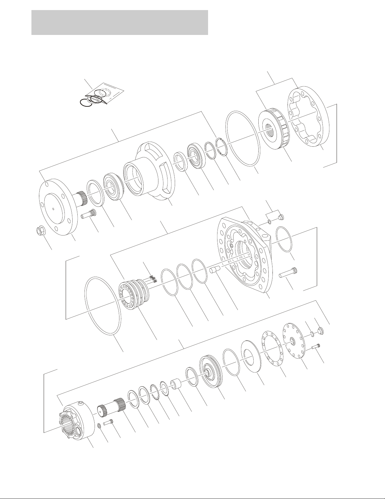
FIGURE 1-2. MOTOR/BRAKE/HUB ASSEMBLY (REAR) (PRIOR TO S/N 0200078291 &
S/N 0200104784 TO PRESENT)
1-6 260MRT 3121802

SECTION 1 FRAME
FIGURE 1-2. MOTOR/BRAKE/HUB ASSEMBLY (REAR) (PRIOR TO S/N 0200078291 & S/N
0200104784 TO PRESENT)
ITEM # PART NUMBER QTY. DESCRIPTION REV.
3160244 Ref. DRIVE MOTOR ASSEMBLY D
1 Not Available 1 Front Housing Assembly (See Items 101 to 108 for
Breakdown)
2 Not Available 1 Rotary Assembly
2A Not Available 1 Rotary without Cam
2B Not Available 1 Cam
3 Not Available 1 Rear Housing Assembly (See Items 201 to 208 for
Breakdown)
4 Use Item 351 2 Seal, Square
5 Not Available 6 Screw, Cap
6Not Used
7 Not Available 1 Brake Assembly (See Items 301 to 327 for Breakdown)
8 Use Item 351 1 Seal, Square
9 7023806 5 Lugnut
10 7023807 5 Stud, Wheel
Ref. FRONT HOUSING ASSEMBLY
101 7022586 1 Shaft
102 Use Item 351 1 Seal, Face
103 7022587 1 Bearing, Front
104 Not Available 1 Casting, Front
105 Use Item 351 1 Seal, Shaft
106 7022588 1 Bearing, Rear
107 Not Available 1 Washer
108 7022589 1 Ring, Split
Ref. REAR HOUSING ASSEMBLY
201 Not Available 1 Ring, Distributor
202 Not Available 9 Spring
203 Use Item 351 1 Seal, Nylon
204 Use Item 351 1 Seal, Nylon
205 Use Item 351 1 Seal, Nylon
206 Not Available 1 Housing, Rear
207 7022590 1 Pin, Stop
208 7022591 1 Plug (O-Ring Supplied with Plug)
Ref. BRAKE ASSEMBLY
301 Not Available 1 Housing, Brake
302 7022592 1 Shaft
303 7022593 1 Shim
304 7022594 1 Shim
305 7022595 15 Disc, Outer Brake
306 7022596 13 Disc, Inner Brake
307 to 313 Not Used
314 7022597 1 Bushing
315 Not Available 8 Washer
316 Not Available 8 Screw, Cap
3121802 260MRT 1-7

SECTION 1 FRAME
FIGURE 1-2. MOTOR/BRAKE/HUB ASSEMBLY (REAR) (PRIOR TO S/N 0200078291 & S/N
0200104784 TO PRESENT) (CONTINUED)
ITEM # PART NUMBER QTY. DESCRIPTION REV.
317 Not Used
318 Use Item 351 1 Ring, Square
319 7022598 1 Piston, Brake
320 Not Used
321 Use Item 351 1 Seal, Outer
322 7022599 1 Washer, Bellville
323 Use Item 351 1 Gasket
324 Not Available 1 Cover, End
325 Use Item 351 1 O-Ring
326 Not Available 12 Screw, Cap
327 7023800 1 Plug
328 to 350 Not Used
— — — — — — — — — —
351 7022585 Seal Kit - (Includes Items 4,8,102,105,203-205,318,321,323 &
325)
1-8 260MRT 3121802

SECTION 1 FRAME
FIGURE 1-2. MOTOR/BRAKE/HUB ASSEMBLY (REAR) (PRIOR TO S/N 0200078291 & S/N
0200104784 TO PRESENT) (CONTINUED)
ITEM # PART NUMBER QTY. DESCRIPTION REV.
3121802 260MRT 1-9

SECTION 1 FRAME
12
13
15
10
11
27
26
25
27
77
76
75
74
72
71
73
78
90
47
59
41
45
135
110
101
106
107
108
109
141
142
102
100
143
112
113
116
111
50
42
40
52
48
91
70
152
151
FIGURE 1-3. MOTOR/BRAKE/HUB ASSEMBLY (REAR) (S/N 0200078291 TO S/N 0200104784
ONLY)
1-10 260MRT 3121802

SECTION 1 FRAME
FIGURE 1-3. MOTOR/BRAKE/HUB ASSEMBLY (REAR) (S/N 0200078291 TO S/N 0200104784
ONLY)
ITEM # PART NUMBER QTY. DESCRIPTION REV.
3160254 Ref. DRIVE MOTOR ASSEMBLY C
1 to 9 Not Used
10 7023279 1 Cylinder Block Assembly
11 Not Serviced 1 Block, Cylinder
12 7023276 1 Piston
13 to 14 Not Used
15 7023278 1 Guide & Keeper Kit
16 to 24 Not Used
25 7023280 1 Cam Assembly
26 Not Serviced 1 Cam
27 7027888 2 O-Ring
28 to 39 Not Used
40 7023281 1 Valving Cover Assembly
41 Not Serviced 1 Cover, Valving
42 7023282 6 Bolt
43 to 44 Not Used
45 Use Item 152 1 O-Ring
46 Not Used
47 7023283 1 Distributor
48 Use Item 152 1 Seal Kit
49 Not Used
50 7023284 1 Plug
51 Not Used
52 7018411 4 Spring
53 to 58 Not Used
59 7023286 1 Pin, Split
60 to 69 Not Used
70 7023287 1 Support Assembly
71 Not Serviced 1 Support, Bearing
72 Use Item 152 1 Seal
73 7023288 1 Bearing
74 7023289 1 Bearing
75 7023302 1 Shim Set
76 7023290 1 Ring
77 7023291 1 Ring, Snap
78 Use Item 152 1 Seal
79 to 89 Not Used
90 7023292 1 Shaft
91 7023303 1 Stud Set
92 7018436 1 Lugnut Set (Not Shown)
93 to 99 Not Used
100 7023293 1 Disc Brake Assembly
101 Not Serviced 1 Body, Brake
102 7023294 8 Bolt
103 to 105 Not Used
106 Use Item 152 1 O-Ring
107 7023295 1 Piston, Brake
3121802 260MRT 1-11

SECTION 1 FRAME
FIGURE 1-3. MOTOR/BRAKE/HUB ASSEMBLY (REAR) (S/N 0200078291 TO S/N 0200104784
ONLY) (CONTINUED)
ITEM # PART NUMBER QTY. DESCRIPTION REV.
108 7023296 1 Washer, Spring
109 7023297 1 Ring, Snap
110 7023298 1 Shaft
111 Use Item 152 1 Seal
112 7018408 1 Bolt
113 Use Item 152 1 Gasket
114 to 115 Not Used
116 7023305 1 Shim
117 to 134 Not Used
135 7023304 1 Brake Disc Kit (Includes Shim Kit)
7026191 1 Brake Shim Kit
136 to 140 Not Used
141 Use Item 152 1 Protector
142 Use Item 152 1 Plug, Dust
143 Use Item 152 1 O-Ring
144 to 151 Not Used
152 7023301 1 Seal Kit - (Includes Items - 27,45,48,72,78,106,111,113,141,
142 & 143)
1-12 260MRT 3121802

SECTION 1 FRAME
FIGURE 1-3. MOTOR/BRAKE/HUB ASSEMBLY (REAR) (S/N 0200078291 TO S/N 0200104784
ONLY) (CONTINUED)
ITEM # PART NUMBER QTY. DESCRIPTION REV.
3121802 260MRT 1-13

SECTION 1 FRAME
251
1
2
4
9
10
101
102
103
104
105
106
107
108
2A
2B
4
201
202
203
204
205
206
208
207
3
5
8
17
18
FIGURE 1-4. MOTOR/HUB ASSEMBLY (FRONT) (PRIOR TO S/N 0200078291 &
S/N 0200112814 TO PRESENT)
1-14 260MRT 3121802

SECTION 1 FRAME
FIGURE 1-4. MOTOR/HUB ASSEMBLY (FRONT) (PRIOR TO S/N 0200078291 & S/N
0200112814 TO PRESENT)
ITEM # PART NUMBER QTY. DESCRIPTION REV.
3160245 Ref. DRIVE MOTOR ASSEMBLY D
1 Not Available 1 Front Housing Assembly (See 101 to 108 for Breakdown)
2 Not Available 1 Rotary Assembly
2A Not Available 1 Rotary without Cam
2B Not Available 1 Cam
3 Not Available 1 Rear Housing Assembly (See 201 to 208 for Breakdown)
4 Use Item 251 2 Seal, Square
5 Not Available 6 Screw, Cap
6 to 8 Not Used
9 7023806 5 Lugnut
10 7023807 5 Stud, Wheel
11 to 15 Not Used
16 7024008 1 Seal, Square
17 7024007 1 Plate, Rear Cover
18 Not Available 8 Screw, Cap
Ref. FRONT HOUSING ASSEMBLY
101 7022586 1 Shaft
102 Use Item 251 1 Seal, Face
103 7022587 1 Bearing, Front
104 Not Available 1 Casting, Front
105 Use Item 251 1 Seal, Shaft
106 7022588 1 Bearing, Rear
107 Not Available 1 Washer
108 Not Available 1 Ring, Split
Ref. REAR HOUSING ASSEMBLY
201 Not Available 1 Ring, Distributor
202 Not Available 9 Spring
203 Use Item 251 1 Seal, Nylon
204 Use Item 251 1 Seal, Nylon
205 Use Item 251 1 Seal, Nylon
206 Not Available 1 Housing, Rear
207 7022590 1 Pin, Stop
208 7022591 1 Plug (O-Ring Supplied with Plug)
209 to 250 Not Used
— — — — — — — — — —
251 7023801 1 Seal Kit (Includes Items - 4,102,105,203-205)
3121802 260MRT 1-15

SECTION 1 FRAME
60
66
92
12
15
10
11
27
26
25
27
77
76
75
74
72
71
73
78
90
47
59
41
45
50
42
40
52
48
91
70
102
FIGURE 1-5. MOTOR/HUB ASSEMBLY (FRONT) (S/N 0200078291 TO S/N 0200112814 ONLY)
1-16 260MRT 3121802

SECTION 1 FRAME
FIGURE 1-5. MOTOR/HUB ASSEMBLY (FRONT) (S/N 0200078291 TO S/N 0200112814 ONLY)
ITEM # PART NUMBER QTY. DESCRIPTION REV.
3160255 Ref. DRIVE MOTOR ASSEMBLY B
1 to 9 Not Used
10 7023279 1 Cylinder Block Assembly
11 Not Serviced 1 Block, Cylinder
12 7023276 1 Piston
13 to 14 Not Used
15 7023278 1 Guide & Keeper Kit
16 to 24 Not Used
25 7023280 1 Cam Assembly
26 Not Serviced 1 Cam
27 7027888 2 O-Ring
28 to 39 Not Used
40 7023281 1 Valving Cover Assembly
41 Not Serviced 1 Cover, Valving
42 7023282 6 Bolt
43 to 44 Not Used
45 Use Item 102 1 O-Ring
46 Not Used
47 7023283 1 Distributor
48 Use Item 102 1 Seal Kit
49 Not Used
50 7023284 1 Plug
51 Not Used
52 7018411 4 Spring
53 to 58 Not Used
59 7023286 1 Pin, Split
60 7023285 1 Back Plate Assembly
61 to 65 Not Used
66 7018435 8 Bolt
67 to 69 Not Used
70 7023287 1 Support Assembly
71 Not Serviced 1 Support, Bearing
72 Use Item 102 1 Seal
73 7023288 1 Bearing
74 7023289 1 Bearing
75 7023302 1 Shim Set
76 7023290 1 Ring
77 7023291 1 Ring, Snap
78 Use Item 102 1 Seal
79 to 89 Not Used
90 7023292 1 Shaft
91 7023303 1 Stud Set
92 7018436 1 Lugnut Set
93 to 101 Not Used
102 7023301 1 Seal Kit - (Includes Items - 27,45,48,72 & 78)
3121802 260MRT 1-17

SECTION 1 FRAME
9
2
0
1
2
0
2
3
0
4
3
0
3
3
0
2
2
0
7
2
0
4
8
4
5
3
2
1
671
3
1
4
1
1
2
1
0
1
1
0
4
1
1
6
1
0
3
1
0
9
1
1
1
1
1
8
1
1
3
1
1
7
1
0
7
1
0
5
1
1
4
1
1
0
1
1
9
1
1
5
1
0
2
1
1
5
1
0
8
3
0
1
O
R
3
0
1
3
0
5
3
0
5
3
0
2
1
0
6
FIGURE 1-6. FRAME MOUNTED COMPONENTS INSTALLATION
1-18 260MRT 3121802

SECTION 1 FRAME
FIGURE 1-6. FRAME MOUNTED COMPONENTS INSTALLATION
ITEM # PART NUMBER QTY. DESCRIPTION REV.
0259805 Ref. ELEVATION SWITCH INSTALLATION E
1 0100011 A/R Compound, Locking
2 0641610 2 Bolt 3/8in-16NC x 1-1/4in
3 0902609 1 Bracket, Limit Switch Mounting
4 4922630 1 Harness, Elevation (See Section 7 for Breakdown)
5 1100110 1 Cam, High Drive Limit Switch
6 3310801 2 Nut #8-32NC
7 3311605 2 Locknut 3/8in-16NC
8 3930820 2 Screw, Machine #8-32NC x 1-1/4in
9 3951603 2 Setscrew 3/8in x 3/8in
10 to 12 Not Used
13 4711600 2 Flatwasher 3/8in Thin
14 4750800 2 Flatwasher #8 Regular
Ref. ELEVATION SWITCH INSTALLATION (AUTO LEVEL LEVELING
JACKS)
0274337 Ref. All Machines except Machines with Level at 6° Slope A
1001118682 Ref. Machines with Level at 6° Slope (Australian Spec Option) (Not
Shown)
A
101 0100011 A/R Compound, Locking
102 0641512 2 Bolt 5/16in-18NC x 1-1/2in
103 0641610 2 Bolt 3/8in-16NC x 1-1/4in
104 1100110 1 Cam, High Drive Limit Switch
105 3200453 1 Mount, Proximity Switch
106 3300474 2 Locknut
107 3310801 2 Nut #8-32NC
108 3311505 2 Locknut 5/16in-18NC
109 3311605 2 Locknut 3/8in-16NC
110 3930334 2 Screw, Panhead
111 3930820 2 Screw, Machine #8-32NC x 1-1/4in
112 3951603 2 Setscrew 3/8in x 3/8in
113 A/R Bracket, Switch Options:
4341007 1 Bracket - 6.75in H x 6in W (17cm H x 15.24 cm W) (All
Machines except Machines with Level at 6° Slope)
A/R Brackets for Machines with Level at 6° Slope (Australian Spec
Option) (Requires Both Brackets) (Not Shown)
0902609 1 Bracket, - 8in H x 5in W (20.3cm H x 12.7 cm W)
4340939 1 Bracket - 8.5in H x 4in W (21.6cm H x 10 cm W)
114 4360502 1 Switch, Proximity Sensor
115 4711500 4 Flatwasher 5/16in Thin
116 4711600 2 Flatwasher 3/8in Thin
117 4750800 2 Flatwasher #8 Regular
118 4922630 1 Cable, 18/2 & Limit Switch
1060680 9ft/2.7m Cable, 18/2
4360548 1 Switch, Limit
4460968 1 Connector, Strain Relief
4460465 2 Socket, Female
119 4923137 1 Harness, Proximity Switch (See Section 7 for Breakdown)
3121802 260MRT 1-19

SECTION 1 FRAME
FIGURE 1-6. FRAME MOUNTED COMPONENTS INSTALLATION (CONTINUED)
ITEM # PART NUMBER QTY. DESCRIPTION REV.
Ref. ALARM INSTALLATIONS
0259816 Ref. Descent Alarm Installation C
0259817 Ref. Motion Alarm Installation C
0273136 Ref. Alarm Installation (S/N 0200112688 to Present) A
201 1 Alarm Options:
0140032 Prior to S/N 0200112688
0140044 S/N112688 to Present
202 0641508 2 Bolt 5/16in-18NC x 1in (Prior to S/N 0200112688)
0641408 2 Bolt 1/4in-20NC x 1in (S/N 0200112688 to Present)
203 Not Used
204 3311505 2 Locknut 5/16in-18NC (Prior to S/N 0200112688)
3311405 2 Locknut 1/4in-20NC (S/N 0200112688 to Present)
205 to 206 Not Used
207 4711500 4 Flatwasher 5/16in Thin (Prior to S/N 0200112688)
4751400 4 Flatwasher 1/4in Regular (S/N 0200112688 to Present)
Ref. LADDER INSTALLATION
0259654 Ref. All Machines except Machines with Level at 6° Slope
Software
1001118677 Ref. Machines with Level at 6° Slope (Australian Spec Option) A
D
301 4 Bolt Options:
0641838 Bolt 1/2in-13NC x 4-3/4in (Prior to S/N 0200192485)
0641824 Bolt 1/2in-13NC x 3in (S/N 0200192485 to Present)
302 3311805 4 Locknut 1/2in-13NC
303 1 Ladder Options:
4846116 Ladder - 25in/63.5cm Height (All Machines except Machines
with Level at 6° Slope)
2930001 Ladder - 30in/72cm Height (Machines with Level at 6° Slope)
(Australian Spec Option)
304 2 Plug, Cap Options:
3520071 Prior to S/N 0200192485
1001109533 S/N 0200192485 to Present
305 4711800 4 Flatwasher 1/2in Thin (S/N 0200076557 to Present)
1-20 260MRT 3121802

SECTION 1 FRAME
FIGURE 1-6. FRAME MOUNTED COMPONENTS INSTALLATION (CONTINUED)
ITEM # PART NUMBER QTY. DESCRIPTION REV.
3121802 260MRT 1-21

SECTION 1 FRAME
FIGURE 1-7. LEVELING JACKS INSTALLATION (PRIOR TO S/N 0200141689)
1-22 260MRT 3121802

SECTION 1 FRAME
FIGURE 1-7. LEVELING JACKS INSTALLATION (PRIOR TO S/N 0200141689)
ITEM # PART NUMBER QTY. DESCRIPTION REV.
0259757 Ref. LEVELING JACKS INSTALLATION I
1 0100011 A/R Compound, Locking
2 0641508 20 Bolt 5/16in-18NC x 1in
3 0641528 4 Bolt 5/16in-18NC x 3-1/2in
4 0641608 16 Bolt 3/8in-16NC x 1in
5 0641816 2 Bolt 1/2in-13NC x 2in
6 0641820 8 Bolt 1/2in-13NC x 2-1/2in
7 0641828 16 Bolt 1/2in-13NC x 3-1/2in
8Not Used
9 1 Jack Cylinder Assembly Options: (See Section 5 for Breakdown)
Use 1684217 Prior to S/N 0200105371 (was p/n 1683966)
1684217 S/N 0200105371 to S/N 0200141689
10 2080053 16 Fastener 5/16in-18NC
11 Not Used
12 3310801 16 Nut #8-32NC
13 3311805 10 Locknut 1/2in-13NC
14 3440420 8 Pin, Roll 1/8in x 1-1/4in
15 3572384 1 Plate, Front Cover
16 3572385 1 Plate, Rear Cover
17 3572388 1 Plate, Top Cover
18 3841326 4 Rod
19 3930820 16 Bolt #8-32NC x 1-1/4in
20 4061003 4 Cover
21 4160116 4 Spring
22 Not Used
23 4420037
24 4420039
25 Use 4420051
26 to 28 Not Used
29 4641150 2 Leveling Jack Control Valve Assembly (See 101 to 104 for
30 4711500 20 Flatwasher 5/16in Thin
31 4711600 16 Flatwasher 3/8in Thin
32 4711800 20 Flatwasher 1/2in Thin
33 4740415 4 Washer, Special
34 4750800 16 Flatwasher #8 Regular
35 4846146 2 Weldment, Leveling Jack
36 0270543 1 Indicator, Level (Not Shown - Located at Platform)
37 1704786 4 Decal - Max Load
38 4922454 2 Harness - Leveling Jack (N.O.) (Not Shown - See Section 7 for
39 4922455 2 Harness - Leveling Jack (N.C.) (Not Shown - See Section 7 for
40 4922456 1 Harness - Leveling Jack (Not Shown - See Section 7 for Break-
41 to 52 Not Used
53 3572324 2 Cover, Rear Axle (S/N 0200128810 to S/N 0200141689)
54 3572326 1 Cover, Center Frame (S/N 0200128810 to S/N 0200141689)
24in/61cm
6ft/1.8m
10ft/3m
Tape, Insulation (Not Shown)
Tape, Non-Skid
Tape, Safety (was p/n 4420052)
Breakdown)
Breakdown)
Breakdown)
down)
— — — — — — — — — —
3121802 260MRT 1-23

SECTION 1 FRAME
FIGURE 1-7. LEVELING JACKS INSTALLATION (PRIOR TO S/N 0200141689) (CONTINUED)
ITEM # PART NUMBER QTY. DESCRIPTION REV.
2902206 2 Kit - Leveling Jack Sub Assembly (Includes Items - 1,3,4,7,9,10,14
thru 21,24,29,31 thru 35,38,39 and Hydraulic Fittings & Hoses)
4641150 Ref. LEVELING JACK CONTROL VALVE ASSEMBLY B
101 0561407 1 Valve, Jack Control
102 2220883 2 Plug
7024822 2 Orifice
103 4641151 2 Cartridge, Relief Valve
7021653 Seal Kit - 4641151 Valve (1 Per Cartridge)
104 4641152 2 Valve, 4-Way
7017454 Cartridge without Coil
7012903 2 Seal Kit - 4641152 Valve (1 Per Cartridge)
7012943 4 Coil (2 Per Cartridge)
1-24 260MRT 3121802
 Loading...