


Operation & Safety
An Oshkosh Corporation Company
Manual
Original Instructions
Keep this manual with machine at all times.
Models
G5-18A
&
2505H
S/N 0160053000 & After including
0160051045, 0160051047,
0160051049, 0160051194 &
0160051359
31200743
Original
May 3, 2013

CALIFORNIA PROPOSITION 65
BATTERY WARNING
Battery posts,
terminals and related
accessories contain
lead and lead compounds,
chemical known to the
State of California
to cause cancer and
reproductive harm.
WASH HANDS
AFTER HANDLING!
CALIFORNIA PROPOSITION 65
EXHAUST WARNING
Diesel Engine exhaust and
some of its constituents
are known to the State of
California to cause cancer,
birth defects and other
reproductive harm.

Revision Log
Revision Log
May 3, 2013 - A - Original Issue of Manual.
REVISION LOG
a31200743

Read This First
Read This First
This manual is a very important tool! Keep it with the machine at all times.
The purpose of this manual is to provide owners, users, operators, lessors, and
lessees with the precautions and operating procedures essential for the safe and
proper machine operation for its intended purpose.
Due to continuous product improvements, JLG Industries, Inc. reserves the right to
make specification changes without prior notification. Contact JLG Industries, Inc.
for updated information.
Operator Qualifications
The operator of the machine must not operate the machine until this manual has
been read, training is accomplished and operation of the machine has been
completed under the supervision of an experienced and qualified operator.
Operation within the U.S.A. requires training per OSHA 1910.178.
Operators of this equipment must possess a valid, applicable driver’s license, be in
good physical and mental condition, have normal reflexes and reaction time, good
vision and depth perception and normal hearing. Operator must not be using
medication which could impair abilities nor be under the influence of alcohol or any
other intoxicant during the work shift.
In addition, the operator must read, understand and comply with instructions
contained in the following material furnished with the telehandler:
• This Operation and Safety Manual
• Telehandler Safety Manual (ANSI only)
• All instructional decals and plates
• Any optional equipment instructions furnished
The operator must also read, understand and comply with all applicable Employer,
Industry and Governmental rules, standards and regulations.
Modifications
Modifications to this machine may affect compliance with Industry Standards
and/or Governmental Regulations. Any modification must be approved by
JLG.
b 31200743

Read This First
This product must comply with all safety related bulletins. Contact JLG Industries,
Inc. or the local authorized JLG representative for information regarding safetyrelated bulletins which may have been issued for this product.
JLG Industries, Inc. sends safety related bulletins to the owner of record of this
machine. Contact JLG Industries, Inc. to ensure that the current owner records are
updated and accurate.
JLG Industries, Inc. must be notified immediately in all instances where JLG
products have been involved in an accident involving bodily injury or death of
personnel or when damage has occurred to personal property or the JLG product.
FOR:
• Accident Reporting and Product Safety Publications
• Current Owner Updates
• Questions Regarding Product Applications and Safety
• Standards and Regulations Compliance Information
• Questions Regarding Product Modifications
CONTACT:
Product Safety and Reliability Department
JLG Industries, Inc.
13224 Fountainhead Plaza
Hagerstown, MD 21742
USA
In USA:
Toll Free: 1-877-JLG-SAFE (1-877-554-7233)
Outside USA:
Phone: +1-717-485-6591
E-mail:
ProductSafety@JLG.com
c31200743
Read This First
1
ULTRA LOW
SULFUR DIESEL
FUEL ONLY
S < 15 mg/kg
1001125387 A
OAH2300
Other Publications Available
Service Manual..........................................................................................31200926
Illustrated Parts Manual.............................................................................31200725
Note: The following standards may be referenced in this manual:
ANSI is compliant to ANSI/ITSDF B56.6
AUS is compliant to AS 1418.19
CE is compliant to EN1459
Refer to the machine Serial Number Plate to identify the applicable compliance
standard.
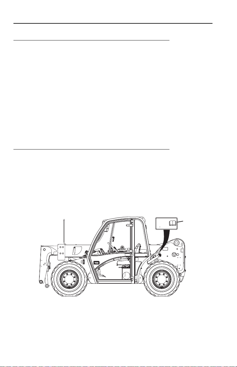
Machine Configuration
Two configurations of each machine are included in this manual. Determine if
machine is equipped with Ultra Low Sulfur Fuel Decal (1) as indicated below.
• If equipped with the Ultra Low Sulfur decal, all specific references to this machine
configuration will be referred to as Ultra Low Sulfur (ULS) from this point forward.
•If not equipped with the Ultra Low Sulfur decal, all specific references to this
machine configuration will be referred to as Low Sulfur (LS) from this point
forward.
d 31200743

Table of Contents
TABLE OF CONTENTS
Revision Log
Read This First
Operator Qualifications ...................................................... b
Modifications ...................................................................... b
Other Publications Available .............................................. d
Machine Configuration ....................................................... d
Table of Contents
Section 1 - General Safety Practices
1.1 Hazard Classification System ..............................................1-1
Safety Alert System and Safety Signal Words................1-1
1.2 General Precautions ............................................................1-1
1.3 Operation Safety ..................................................................1-2
Electrical Hazards ...........................................................1-2
Tip Over Hazard..............................................................1-3
Travel Hazard ................................................................. 1-6
Load Falling Hazard ........................................................1-7
Lifting Personnel .............................................................1-8
Driving Hazards on Slopes .............................................1-9
Pinch Points and Crush Hazards ..................................1-10
Fall Hazard....................................................................1-12
Chemical Hazards.........................................................1-13
Table of Contents
Section 2 - Pre-Operation and Inspection
2.1 Pre-Operation Check and Inspection................................... 2-1
2.2 Safety Decals....................................................................... 2-4
ANSI (G5-18A, if equipped) ............................................ 2-4
ISO (2505H) (G5-18A, if equipped) ................................2-7
2.3 Walk-Around Inspection..................................................... 2-10
2.4 Warm-Up and Operational Checks ....................................2-12
Warm-Up Check ...........................................................2-12
Operational Check ........................................................2-12
2.5 Operator Cab .....................................................................2-13
2.6 Windows ............................................................................2-14
Cab Door Window (if equipped)....................................2-14
Rear Window ................................................................2-15
i31200743

Table of Contents
Section 3 - Controls and Indicators
3.1 General................................................................................ 3-1
3.2 Controls ............................................................................... 3-2
Park Brake...................................................................... 3-4
Parking Procedure.......................................................... 3-5
Ignition ............................................................................ 3-6
Transmission Control Lever............................................ 3-7
Load Stability Indicator - LSI (2505H)............................. 3-8
LSI Override Switch (2505H)........................................ 3-10
Steering Column Adjuster (if equipped)........................ 3-11
Instrument Panel .......................................................... 3-12
Joystick......................................................................... 3-14
Right Hand Console ..................................................... 3-16
Accessory Control Lever (if equipped) ......................... 3-18
Reversing Fan (if equipped) ......................................... 3-19
3.3 Steer Modes ...................................................................... 3-20
Steer Mode Change ..................................................... 3-20
3.4 Operator Seat.................................................................... 3-21
Operator Presence (CE & AUS) ................................... 3-21
Adjustments.................................................................. 3-22
Seat Belt ....................................................................... 3-23
3.5 Boom Angle and Extension Indicators .............................. 3-24
Section 4 - Operation
4.1 Engine ................................................................................. 4-1
Starting the Engine ......................................................... 4-1
Battery Boosted Starting................................................. 4-2
Normal Engine Operation ............................................... 4-3
Shut-Down Procedure .................................................... 4-3
4.2 Operating with a Non-Suspended Load .............................. 4-4
Lift Load Safely............................................................... 4-4
Before Picking Up a Load............................................... 4-4
Transporting a Load ....................................................... 4-5
Leveling Procedure......................................................... 4-5
Placing a Load................................................................ 4-6
Disengaging a Load........................................................ 4-6
4.3 Operating with a Suspended Load (ANSI & CE)................. 4-7
Lift Load Safely............................................................... 4-7
Picking Up a Suspended Load ....................................... 4-7
Transporting a Suspended Load .................................... 4-8
Leveling Procedure......................................................... 4-8
Placing a Suspended Load............................................. 4-9
Disengaging a Suspended Load .................................... 4-9
ii 31200743

4.4 Road Operation (2505H) ...................................................4-10
4.5 Loading and Securing for Transport ..................................4-11
Tiedown ........................................................................4-11
Lifting ............................................................................4-12
Section 5 - Attachments and Hitches
5.1 Approved Attachments ........................................................5-1
5.2 Unapproved Attachments ....................................................5-1
5.3 JLG Supplied Attachments ..................................................5-2
5.4 Telehandler/Attachment/Fork Capacity................................5-4
5.5 Use of the Capacity Chart....................................................5-5
Capacity Indicator Locations ...........................................5-5
Sample Capacity Chart (ANSI & CE)..............................5-6
Sample Capacity Chart (AUS) ........................................ 5-7
Example ..........................................................................5-8
5.6 Attachment Installation ........................................................5-9
Standard Quick Attach ....................................................5-9
Universal Quick Attach (UQC) ......................................5-12
5.7 Hydraulic Operated Attachment.........................................5-14
5.8 Adjusting/Moving Forks......................................................5-15
5.9 Attachment Operation ........................................................5-16
Carriage with Forks .......................................................5-18
Fork Mounted Hook (ANSI & CE) .................................5-19
Side Tilt Carriage .......................................................... 5-20
Side Shift Carriage ........................................................5-22
Bucket ...........................................................................5-24
Grapple Bucket .............................................................5-26
5.10 Hitches ...............................................................................5-28
Adjustable Auto Hitch....................................................5-29
Pin Hitch - CUNA C.......................................................5-30
EEC Manual Pin Hitch ..................................................5-31
Table of Contents
Section 6 - Emergency Procedures
6.1 Towing a Disabled Product ..................................................6-1
Moving Short Distances ..................................................6-1
Moving Longer Distances ............................................... 6-1
6.2 Emergency Lowering of Boom.............................................6-2
6.3 Emergency Exit from Enclosed Cab .................................... 6-2
iii31200743

Table of Contents
Section 7 - Lubrication and Maintenance
7.1 Introduction.......................................................................... 7-1
Clothing and Safety Gear ............................................... 7-1
7.2 General Maintenance Instructions....................................... 7-2
7.3 Service and Maintenance Schedule.................................... 7-3
10 & 1st 50 & 50 Hour Maintenance Schedule............... 7-3
1st 250, 250 & 500 Hour Maintenance Schedule........... 7-4
1000 & 1500 Hour Maintenance Schedule..................... 7-5
7.4 Lubrication Schedules ......................................................... 7-6
250 Hour Lubrication Schedule ...................................... 7-6
7.5 Operator Maintenance Instructions ..................................... 7-8
Fuel System.................................................................... 7-8
Engine Oil ..................................................................... 7-10
Hydraulic Oil ................................................................. 7-11
Tires.............................................................................. 7-12
Air Intake System ......................................................... 7-14
Engine Cooling System ................................................ 7-16
Battery .......................................................................... 7-17
Brake System ............................................................... 7-18
Windshield Washer System (if equipped)..................... 7-19
Section 8 - Additional Checks
8.1 General................................................................................ 8-1
8.2 Load Stability Indicator System (2505H) ............................. 8-1
Section 9 - Specifications
9.1 Product Specifications ......................................................... 9-1
Fluids .............................................................................. 9-1
Capacities....................................................................... 9-3
Tires................................................................................ 9-3
Performance ................................................................... 9-4
Dimensions..................................................................... 9-5
Declaration of Vibration (CE).......................................... 9-7
Noise Emission Level (CE)............................................. 9-7
Machine Towing Capacity .............................................. 9-7
Index
Inspection, Maintenance and Repair Log
iv 31200743

Section 1 - General Safety Practices
DANGER
OW0010
WARNING
OW0021
CAUTION
OW0031
SECTION 1 - GENERAL SAFETY PRACTICES
1.1 HAZARD CLASSIFICATION SYSTEM
Safety Alert System and Safety Signal Words
DANGER indicates an imminently hazardous situation which, if not avoided, will
result in death or serious injury.
WARNIN G indicates a potentially hazardous situation which, if not avoided, could
result in death or serious injury.
CAUTION indicates a potentiality hazardous situation which, if not avoided, may
result in minor or moderate injury.
1.2 GENERAL PRECAUTIONS
WARNING
Before operation, read and understand this manual. Failure to comply with the
safety precautions listed in this manual could result in machine damage, property
damage, personal injury or death.
1-131200743
Section 1 - General Safety Practices
OW0040
10 FT
(3 M)
1.3 OPERATION SAFETY
Note: The manufacturer has no direct control over machine application and
operation. Therefore, safety issues listed in this manual are non-exhaustive. The
user and operator are responsible for conforming with good safety practices.
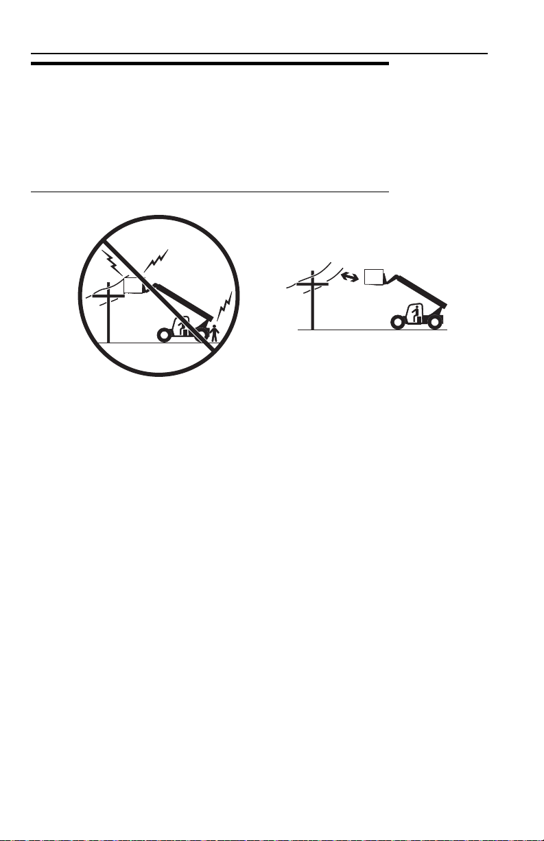
Electrical Hazards
• This machine is not insulated and does not provide protection from contact or
being near electrical current.
• NEVER operate the telehandler in an area where overhead power lines,
overhead or underground cables, or other power sources may exist without
ensuring the appropriate power or utility company de-energizes the lines.
• Always check for power lines before raising the boom.
• Follow employer, local and governmental regulations for clearance from
powerlines.
1-2 31200743
Section 1 - General Safety Practices
OW0050
OW0080
OW0100
4 FT
(1,2 M)
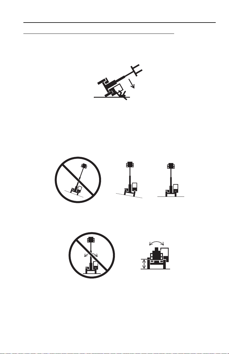
Tip Over Hazard
General
• For additional load requirements, refer to the appropriate capacity chart.
• Never use an attachment without the appropriate JLG approved capacity chart
installed on the telehandler.
• Understand how to properly use the capacity charts located in cab.
• DO NOT exceed rated lift capacity.
• Be sure that the ground conditions are able to support the machine.
• DO NOT raise boom unless frame is level (0 degrees), unless otherwise noted
on capacity chart.
• DO NOT level machine with boom/attachment above 4 ft (1,2 m).
(AUS - DO NOT level machine with load more than 11.8 in (300 mm) above
ground surface.)
1-331200743

Section 1 - General Safety Practices
OH2291
OH20911
OH2221
• MAINTAIN proper tire pressure at all times. If proper tire pressures are not
maintained, this machine could tip over.
• Refer to manufacturer’s specifications for proper fill ratio and pressure
requirements for tires equipped with ballast.
• Always wear the seat belt.
• Keep head, arms, hands, legs and all other body parts inside operator’s cab at all
times.
If the telehandler starts to tip over:
• DO NOT JUMP
• BRACE YOURSELF and STAY WITH THE MACHINE
• KEEP YOUR SEAT BELT FASTENED
• HOLD ON FIRMLY
• LEAN AWAY FROM THE POINT OF IMPACT
1-4 31200743
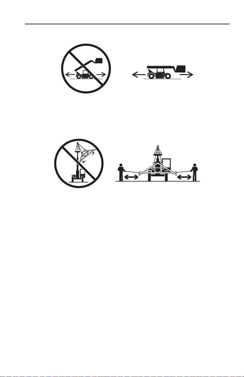
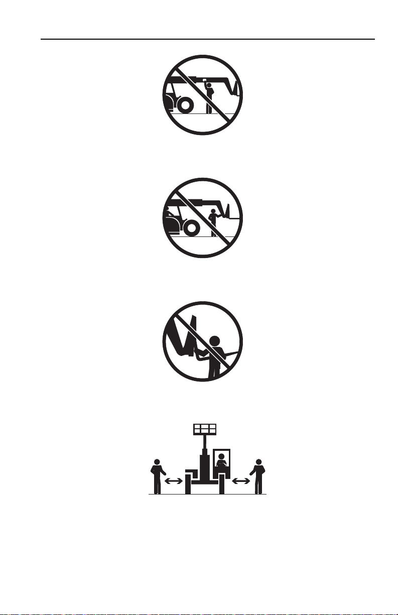
Non-Suspended Load
OW0060
O
W0150
• DO NOT drive with boom raised.
Suspended Load
Section 1 - General Safety Practices
• Tether suspended loads to restrict movement.
• Weight of all rigging (slings, etc.) must be included as part of load.
• Beware of wind. Wind can cause a suspended load to swing and cause
dangerous side loads - even with tag lines.
• DO NOT attempt to use telehandler frame-leveling to compensate for load swing.
• Keep heavy part of load closest to attachment.
• Never drag the load; lift vertically.
When driving with a suspended load:
• Start, travel, turn and stop slowly to prevent load from swinging.
• DO NOT extend boom.
• DO NOT raise the load more than 11.8 in (300 mm) above ground surface or
the boom more than 45°.
• DO NOT exceed walking speed.
1-531200743

Section 1 - General Safety Practices
OAL2030
2-Wheel Front Steer 4-Wheel Circle Steer 4-Wheel Crab Steer
Travel Hazard
• Steering characteristics differ between steer modes. Identify the steer mode
settings of the telehandler being operated.
• DO NOT change steer modes while traveling. Steer modes must be changed
while telehandler is stationary.
• Visually verify proper wheel alignment after each steer mode change.
• Ensure that adequate clearance is provided for both rear tail swing and front fork
swing.
• Look out for and avoid other personnel, machinery and vehicles in the area. Use
a spotter if you DO NOT have a clear view.
• Before moving be sure of a clear path and sound horn.
• When driving, retract boom and keep boom/attachment as low as possible while
maintaining visibility of mirrors and maximum visibility of path of travel.
• Always look in the direction of travel.
• Always check boom clearances carefully before driving underneath overhead
obstructions. Position attachment/load to clear obstacles.
• When driving in high speed, use only front wheel steer (if steering modes are
selectable).
1-6 31200743

Section 1 - General Safety Practices
OW0130
Load Falling Hazard
• Never suspend load from forks or other parts of carriage.
• DO NOT burn or drill holes in fork(s).
• Forks must be centered under load and spaced apart as far as possible.
1-731200743

Section 1 - General Safety Practices
OW0170
O
W0190
Lifting Personnel
• When lifting personnel, USE ONLY an approved personnel work platform, with
proper capacity chart displayed in the cab.
• DO NOT drive machine from cab when personnel are in platform.
1-8 31200743

Section 1 - General Safety Practices
OW0200
Driving Hazards on Slopes
To maintain sufficient traction and braking capabilities, travel on slopes as follows:
• When unloaded, drive with forks pointed downhill.
• When loaded, drive with the forks pointed uphill.
• For additional travel requirements, refer to the appropriate capacity chart.
• To avoid overspeeding the engine and drivetrain when driving down slopes,
downshift to a lower gear and use the service brake as necessary to maintain a
slow speed. DO NOT shift into neutral and coast downhill.
• Avoid excessively steep slopes or unstable surfaces. To avoid tip over DO NOT
drive across excessively steep slopes under any circumstances.
• Avoid turning on a slope. Never engage “inching” or shift to “Neutral” when going
downhill.
• DO NOT park on a slope.
1-931200743

Section 1 - General Safety Practices
OW0210
OW0220
O
W0230
Pinch Points and Crush Hazards
Stay clear of pinch points and rotating parts on the telehandler.
• Stay clear of moving parts while engine is running.
• Keep clear of steering tires and frame or other objects.
• Keep clear from under boom.
1-10 31200743
Section 1 - General Safety Practices
OW0240
OW0250
OW0260
OW0960
• Keep clear of boom holes.
• Keep arms and hands clear of attachment tilt cylinder.
• Keep hands and fingers clear of carriage and forks.
• Keep others away while operating.
1-1131200743

Section 1 - General Safety Practices
OW0280
OW0290
Fall Hazard
• Enter using the proper hand holds and steps provided. Always maintain 3-point
contact when mounting or dismounting. Never grab control levers or steering
wheel when mounting or dismounting the machine.
• DO NOT get off the machine until the shutdown procedure on page 4-4 has been
performed.
• DO NOT carry riders. Riders could fall off machine causing death or serious
injury.
1-12 31200743

Section 1 - General Safety Practices
OW0300
OW0950
Chemical Hazards
Exhaust Fumes
• DO NOT operate machine in an enclosed area without proper ventilation.
• DO NOT operate the machine in hazardous environments unless approved for
that purpose by JLG and site owner. Sparks from the electrical system and the
engine exhaust can cause an explosion.
Flammable Fuel
• DO NOT fill the fuel tank or service the fuel system near an open flame, sparks
or smoking materials. Engine fuel is flammable and can cause a fire and/or
explosion.
Hydraulic Fluid
• DO NOT attempt to repair or tighten any hydraulic hoses or fittings while the
engine is running or when the hydraulic system is under pressure.
• Stop engine and relieve trapped pressure. Fluid in the hydraulic system is under
enough pressure that it can penetrate the skin.
• DO NOT use your hand to check for leaks. Use a piece of cardboard or paper to
search for leaks. Wear gloves to protect hands from spraying fluid.
1-1331200743

Section 1 - General Safety Practices
This Page Intentionally Left Blank
1-14 31200743
Section 2 - Pre-Operation and Inspection
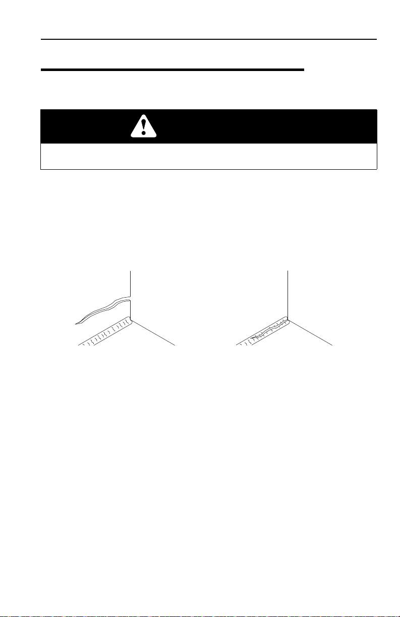
OAH1000
PARENT METAL CRACK WELD CRACK
SECTION 2 - PRE-OPERATION AND INSPECTION
2.1 PRE-OPERATION CHECK AND INSPECTION
Note: Complete all required maintenance before operating unit.
WARNING
FALL HAZARD. Use extreme caution when checking items beyond your normal
reach. Use an approved ladder.
The pre-operation check & inspection, performed at beginning of each work shift or
at each change of operator, should include the following:
1. Cleanliness - Check all surfaces for leakage (oil, fuel or battery fluid) or foreign
objects. Report any leakage to the proper maintenance personnel.
2. Structure - Inspect the machine structure for dents, damage, weld or parent
metal cracks or other discrepancies.
3. Safety Decals - Ensure all safety decals are legible and in place. Clean or
replace as required. See page 2-4 for details.
4. Operation and Safety Manuals - Operation & Safety Manual and AEM Safety
Manual (ANSI only) are located in cab manual holder.
5. Walk-Around Inspection - See page 2-10 for details.
6. Fluid Levels - Check fluids, including fuel, brake fluid, hydraulic oil, engine oil
and coolant. When adding fluids, refer to Section 7 - Lubrication and
Maintenance and Section 9 - Specifications to determine proper type and
intervals. Before removing filler caps or fill plugs, wipe all dirt and grease away
from the ports. If dirt enters these ports, it can severely reduce component life.
7. Attachments/Accessories - Ensure correct capacity charts are installed on the
telehandler. If provided, reference the Operation & Safety Manual of each
attachment or accessory installed for specific inspection, operation and
maintenance instructions.
2-131200743

Section 2 - Pre-Operation and Inspection
8. Operational Check - Once the walk-around inspection is complete, perform a
warm-up and operational check (see page 2-12) of all systems in an area free
of overhead and ground level obstructions. See Section 3 - Controls and
Indicators for more specific operating instructions.
WARNING
If telehandler does not operate properly, immediately bring machine to a stop,
lower boom and attachment to ground and stop the engine. Determine cause and
correct before continued use.
2-2 31200743

Section 2 - Pre-Operation and Inspection
This Page Intentionally Left Blank
2-331200743
Section 2 - Pre-Operation and Inspection
OAH2231
8005870C
8005870
1701500
1701500
1706302
1702300
1702300
4100181
4100181
1706301A
1706301
1001139578
1706301A
1706301
(in engine
compartment)
1001081395
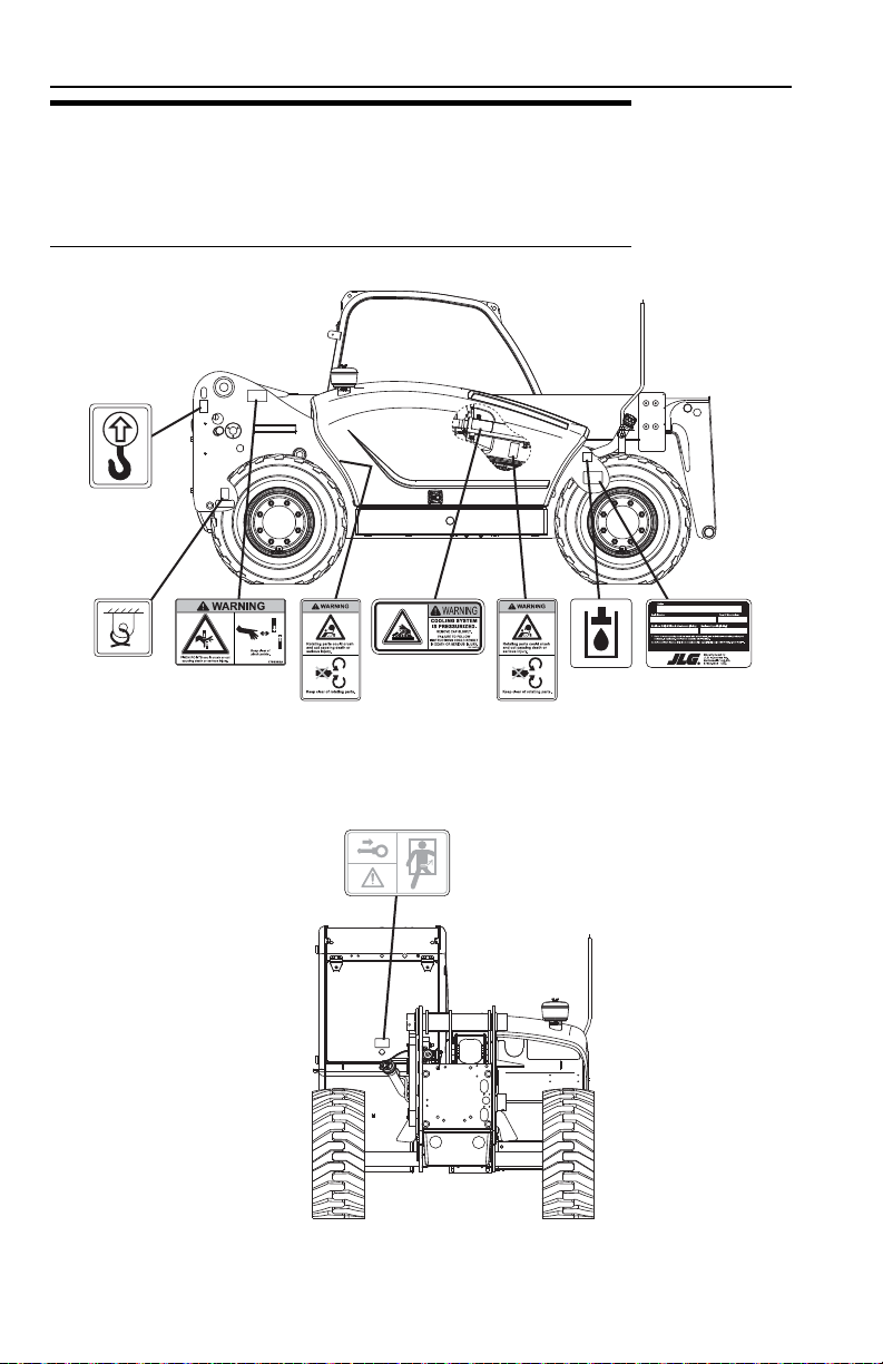
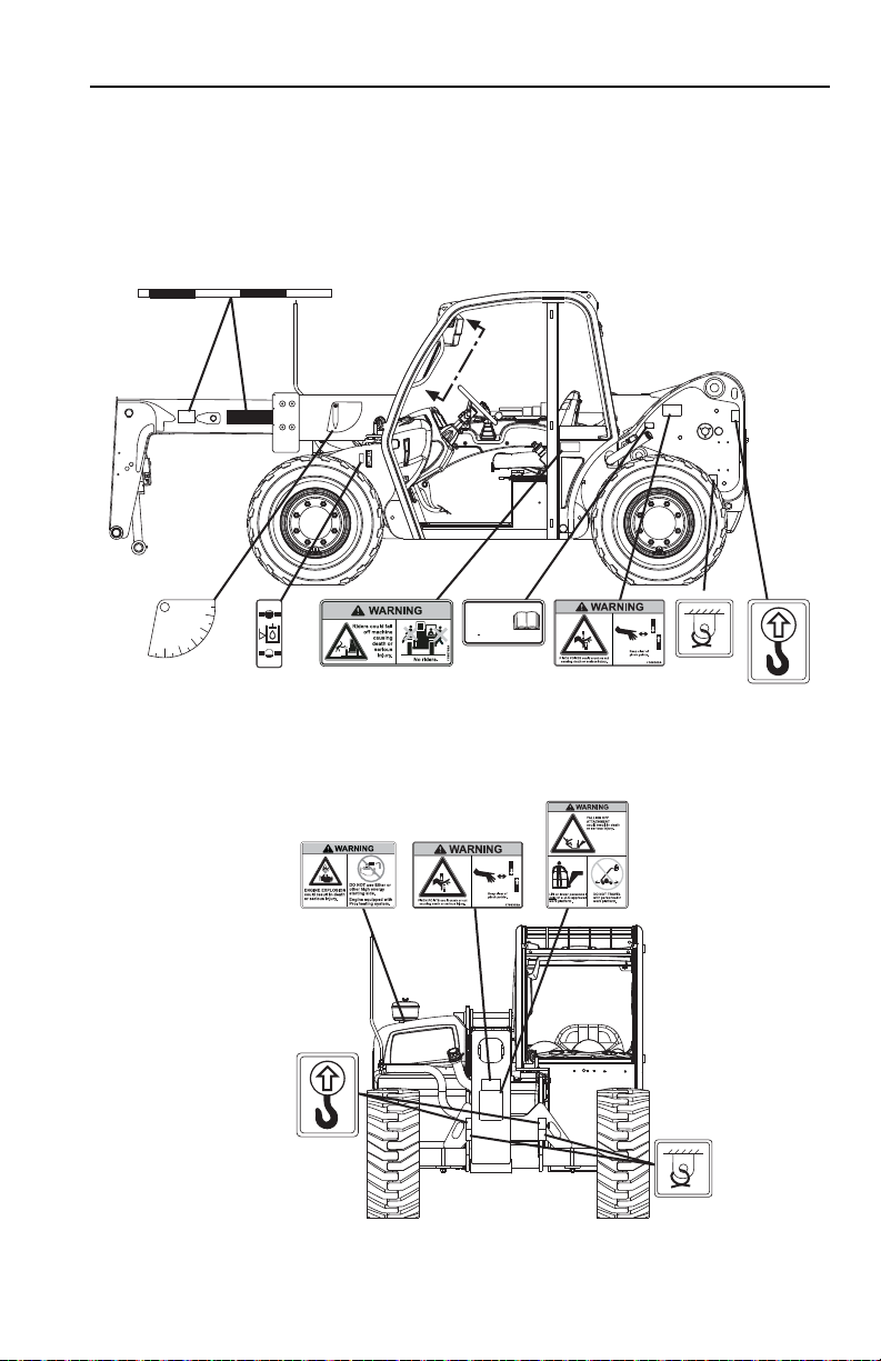
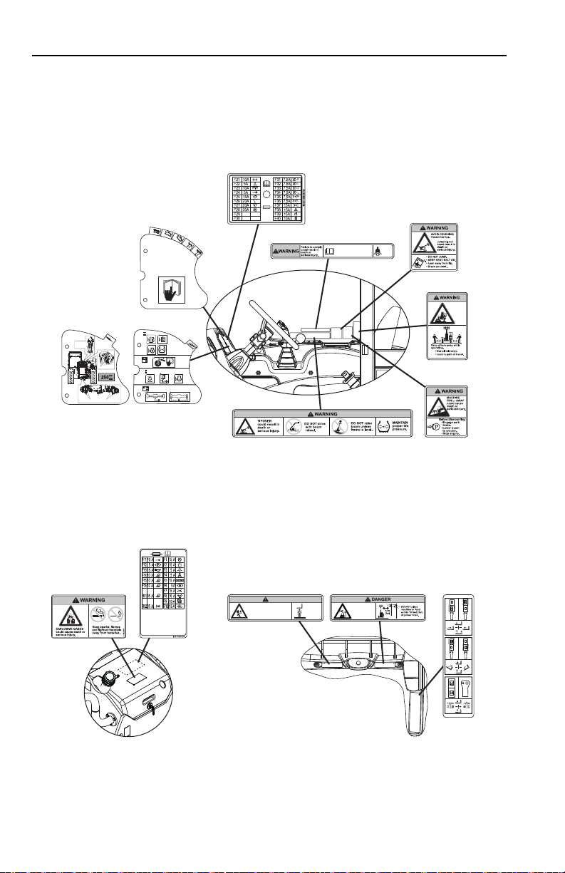
2.2 SAFETY DECALS
Ensure all DANGER, WARNING, CAUTION and instructional decals and proper
capacity charts are legible and in place. Clean and replace as required.
ANSI (G5-18A, if equipped)
2-4 31200743
Section 2 - Pre-Operation and Inspection
OAH2241
B
A
B C D E
A
1001099783
-10
0
10
20
30
40
50
60
7
0
8
0
4105262
1702300
1702300
1701500
1701500
1706302
1706768
91563220
91563220 REV A
1001125387
ULTRA LOW
SULFUR DIESEL
FUEL ONLY
S < 15 mg/kg
1001125387 A
1706300
1706300C
1706302
1706298A
1706298
1701500
1701500
1702300
1702300
A
A
2-531200743
Section 2 - Pre-Operation and Inspection
OAL3830
1706299A
CONTACTING
POWERLINES
willresult in death
orserious injury.
1706299
1706850A
CRUSHING HAZARD
Keepothers
awaywhile
operating.
Loweringboom or falling load could
causedeath or serious injury.
WARNING
1706850
1001101071B
1001101071
1706296
1001156576
Fasten
seat
belt.
1706303A
Operatormust be trained and
mustread and understand
allcapacity charts, operator
andsafety manuals.
1706303
1706306A
1706306
1706851A
1706851
1706304A
RUN-OVER
HAZARD
couldcause
deathor
serious
injury.
1706304
Axle Trunnions
Axle Kingpins (Both Axles)
Boom Pivot
Tilt Cylinder &
Carriage Pivot
1001100107
1001146038
D
50
10
50
D
250
1
2
3
4
5
XXXXX
XXX
1706767A
1706767
1001156577
(behind chart plate)
VIEW A-A
VIEW OF BATTERY COVER
CAPACITY
CHARTS
2-6 31200743

Section 2 - Pre-Operation and Inspection
OAH2251
8005870C
8005870
3931579
20 - 2603207
30 - 1001081158
(GERMANY)
20
1701500
1701500
1702300
1702300
1001081395 (ANSI)
1001098487 (CE)
1001107655 (AUS)
4100181
4100181
8005671
8005671
1706285
1706285
3700016
3700016
8005670
20 - 2603207
30 - 1001081158
(GERMANY)
20
1706292
1001139942
1001139069
3700016
1001138051
(IF EQUIPPED - BELGIUM,
GERMANY, ITALY, SPAIN)
JLG MANUFACTURING EUROPE BVBA
1001138051
HOMOLOGATION NUMBER:
NUMERO DI OMOLOGAZIONE:
GENEHMIGUNGS NUMMER:
NUMERO IDENTIFICAZIONE:
VEHICLE IDENTIFICATION NUMBER:
FAHRZEUG-IDENTIFIZIERUNGS-NUMMER:
ALLOWED TOTAL WEIGHT:
MASSA TOTALEAMMISSIBILE:
ZUL. GESAMTGEWICHT:
ALLOWED FRONTAXLE WEIGHT:
CARICOAMMISSIBILE SULLASSEANTERIORE:
ZUL.ACHSLAST VORN:
ALLOWED REARAXLE WEIGHT:
CARICOAMMISSIBILE SULLASSE POSTERIORE:
ZUL.ACHSLAST HINTEN:
Kg
Kg
Kg
PERMISSIBLE TOWABLE MASS:
MASSA RIMORCHIABILEAMMISSIBILE:
TECHNISCH ZULAESSIGEANHAENGELAST:
-:UNBRAKED TOWABLE MASS
MASSA RIMORCHIABILE NON FRENATA:
UNGEBREMSTEANHAENGELAST:
-:INDEPENDENTLY-BRAKED TOWABLE MASS
MASSA RIMORCHIABILE CON FRENATURA INDIPENDENTE:
ANHAENGELAST FUER UNABHAENGIGE BREMSUNG:
-:INERTIA-BRAKED TOWABLE MASS
MASSA RIMORCHIABILE CON FRENATURAAD INERZIA:
AUFLAUFGEBREMSTEANHAENGELAST:
-TOWABLE MASS FITTED WITHANASSISTED BRAKING
SYSTEM:
(HYDRAULIC OR PNEUMATIC)
MASSA RIMORCHIABILE CON FRENATURAASSISTITA:
(IDRAULICA O PNEUMATICA)
Kg
Kg
Kg
Kg
TYPE/MODEL:
TIPO/MODELLO:
TYP/MODELL:
TIPO/MODELO:
NÚMERO DE HOMOLOGACIÓN:
NÚMERO DE IDENTIFICACIÓN:
MASA TOTALAUTORIZADA:
CARGAAUTORIZADA SOBRE EL EJE DELANTERO:
CARGAAUTORIZADA SOBRE EL EJE TRASERO:
MASA REMOLCABLEADMISIBLE:
MASA REMOLCABLE NO FRENADA:
MASA REMOLCABLE CON FRENADO INDEPENDIENTE:
MASA REMOLCABLE FRENADA POR INERCIA:
HYDRAULSCH ODER PNEUMATISCH GEBREMSTE
ANHAENGELAST:
MASA REMOLCABLE CON FRENADOASISTID:
(HIDRÁULICO-NEUMÁTICO)
YEAR OF MANUFACTURE:
ANNO DI FABRICAZIONE:
BAUJAHR:
AÑO DE FABRICACIÓN:
ISO (2505H) (G5-18A, if equipped)
2-731200743

Section 2 - Pre-Operation and Inspection
OAH2262
1701500
1701500
1702300
1702300
1706292
1706282
1706098B
1706098
B C D E
A
1001099783
-10
0
10
20
30
40
50
60
7
0
8
0
4105262
1702300
1702300
1701500
1701500
B
A
91563220
91563220 REV A
1001125387
ULTRA LOW
SULFUR DIESEL
FUEL ONLY
S < 15 mg/kg
1001125387 A
1001092878
3700016
20 - 2603207
30 - 1001081158
(GERMANY)
20
TBD
L
WA
04
dB
1
1705084
(CE & AUS)
1706292
3700016
3700016
1706209
ONPOFF
P
(IF EQUIPPED
FOR ULS)
A
A
2-8 31200743

Section 2 - Pre-Operation and Inspection
OAL3840
1001101071B
1001101071
1001127546 A
1001127546
(CE & AUS)
1706284
1001092877
1706281
1001156576
Axle Trunnions
Axle Kingpins (Both Axles)
Boom Pivot
Tilt Cylinder &
Carriage Pivot
1001100107
1001146038
D
50
10
50
D
250
1
2
3
4
5
XXXXX
XXX
8005671
8005671
1706287
1706289
1706283
1706293
1706288
XXXXX
XXXXX:XXXX
1001156577
(behind chart plate)
VIEW A-A
VIEW OF BATTERY COVER
CAPACITY
CHARTS
EN15830
CHARTS (CE)
2-931200743

Section 2 - Pre-Operation and Inspection
OAH2270
1
2
18
3
4
7
12
15
13
16
17
19
5
6
9
8
10
14
11
2.3 WALK-AROUND INSPECTION
Begin your walk-around inspection at item 1, as noted below. Continue to your right
(counterclockwise when viewed from top) checking each item in sequence.
INSPECTION NOTE: On all components, make sure there are no loose or missing
parts, that they are securely fastened and no visible leaks or excessive wear exists
in addition to any other criteria mentioned. Inspect all structural members including
attachment for cracks, excessive corrosion and other damage.
1. Boom Sections and Lift, Tilt, Extend/Retract, Compensating (Slave) Cylinders
• Check front, top, side and rear wear pads for presence of grease.
• Pivot pins secure; hydraulic hoses undamaged, not leaking.
2. Battery Compartment
properly secured.
- Cables tight, no visible damage or corrosion. Cover
2-10 31200743
-

Section 2 - Pre-Operation and Inspection
3. Wheel/Tire Assembly - Properly inflated and secured; no loose or missing lug
nuts. Inspect for worn tread, cuts, tears or other discrepancies.
4. Mirrors
5. Cab and Electrical
6. Wheel/Tire Assembly
7. Rear Axle
8. Wheel Chock
9. Main Control Valve
10. Boom Prop
11. LSI Sensor
12. Wheel/Tire Assembly
13. Air Precleaner
14. Boom Sensor
15. Engine Compartment
16. Mirrors
17. Wheel/Tire Assembly
- Clean and undamaged.
-
• General appearance; no visible damage.
• Frame level indicator(s) and window glass undamaged and clean.
• Gauges, switches, joystick, foot controls and horn operational.
• Check seat belt for damage, replace belt if frayed or cut webbing, damaged
buckles or loose mounting hardware.
- Properly inflated and secured; no loose or missing lug
nuts. Inspect for worn tread, cuts, tears or other discrepancies.
- Steer cylinders undamaged, not leaking; pivot pins secure;
hydraulic hoses undamaged, not leaking.
(if equipped) - See inspection note.
- See inspection note.
(2505H) - See inspection note.
(2505H) - See inspection note.
- Properly inflated and secured; no loose or missing lug
nuts. Inspect for worn tread, cuts, tears or other discrepancies.
(if equipped) - Check and clean as required.
(2505H) - See Inspection Note.
-
• Drive belts, check condition and replace as required.
• Engine mounts - See inspection note.
• Engine cover properly secured.
- Clean and undamaged.
- Properly inflated and secured; no loose or missing lug
nuts. Inspect for worn tread, cuts, tears or other discrepancies.
18. Front Axle
undamaged, not leaking.
19. Attachment
- Steer cylinders undamaged, not leaking; hydraulic hoses
- Properly installed, see “Attachment Installation” on page 5-9.
2-1131200743

Section 2 - Pre-Operation and Inspection
2.4 WARM-UP AND OPERATIONAL CHECKS
Warm-Up Check
During warm-up period, check:
1. Heater, defroster and windshield wiper (if equipped).
2. Check all lighting systems (if equipped) for proper operation.
3. Adjust mirror(s) for maximum visibility.
WARNING
CUT/CRUSH/BURN HAZARD. Keep engine cover closed while engine is
running.
Operational Check
When engine warms, perform an operational check:
1. Service brake and parking brake operation.
2. Forward and reverse travel.
3. Steering in both directions with engine at low idle (steering lock to lock will not
be reached). Check in each steering mode.
4. Horn and back-up alarm. Must be audible from inside operators cab with engine
running.
5. All joystick functions - operate smoothly and correctly.
6. Perform any additional checks described in Section 8.
2-12 31200743

Section 2 - Pre-Operation and Inspection
2.5 OPERATOR CAB
The telehandler is equipped with an open or enclosed ROPS/FOPS cab.
WARNING
Never operate telehandler unless the overhead guard and cab structure are in
good condition. Any modification to this machine must be approved by JLG to
assure compliance with ROPS/FOPS certification for this cab/machine
configuration. If damaged, the CAB CANNOT BE REPAIRED. It must be
REPLACED.
2-1331200743

Section 2 - Pre-Operation and Inspection
OAL1670
1
2
3
4
2.6 WINDOWS
Keep all windows and mirrors clean and unobstructed.
Cab Door Window (if equipped)
• Cab door (1) must be closed during operation.
• During operation the cab door window (2) must either be latched open or closed.
• Open the cab door window using lever (3) and secure it in the latch.
• Rotate knob (4) inside the cab or outside the cab to unlatch the window.
2-14 31200743

Section 2 - Pre-Operation and Inspection
5
6
OAM2110
Rear Window
• Lift lever (5) and push to open rear window (6).
• Lift lever and pull to close.
2-1531200743

Section 2 - Pre-Operation and Inspection
This Page Intentionally Left Blank
2-16 31200743

Section 3 - Controls and Indicators
SECTION 3 - CONTROLS AND INDICATORS
3.1 GENERAL
This section provides the necessary information needed to understand control
functions.
3-131200743

Section 3 - Controls and Indicators
OAH2130
2
3
5
6
7
9
11
12
16
18
8
10
15
1
4
14
15
13
17
3.2 CONTROLS
1. Park Brake Lever (2505H): See page 3-4.
2. Accelerator Pedal
speed.
3. Ignition Switch
4. Service Brake Pedal
speed.
5. Tilt Steering Column
6. Quick Attach Switch
hydraulically lock or unlock an attachment.
7. Transmission Control Lever
8. Park Brake Switch
LSI Override Switch
9. Instrument Panel
3-2 31200743
: Pressing down the pedal increases engine and hydraulic
: Key activated. See page 3-6.
: The further the pedal is depressed, the slower the travel
(if equipped): See page 3-11.
(if equipped): Used in conjunction with the joystick to
: See page 3-7.
(G5-18A): See page 3-4.
(2505H): See page 3-10.
: See page 3-12.

Section 3 - Controls and Indicators
10. Steering Wheel: Turning the steering wheel to the left or right steers the
machine in the corresponding direction. Three steering modes are available.
See “Steer Modes” on page 3-20.
11. Horn Button
12. Frame Level Indicator
condition of the telehandler.
13. Accessory Control Lever
14. LSI Indicator
: Depress button to sound horn.
: Enables operator to determine the left to right level
(if equipped): See page 3-18.
(2505H): See page 3-8.
15. Power Outlet
16. Joystick
17. Longitudinal Level Indicator
back level condition of the telehandler.
18. Right Hand Console
: 12V receptacle.
: See page 3-14.
(AUS): Enables operator to determine the front to
: See page 3-16.
3-331200743

Section 3 - Controls and Indicators
OAL1382
1
Park Brake
Park Brake Switch (G5-18A)
Park brake switch (1) controls the application and release of the park brake.
Indicator light on instrument panel illuminates to indicate brake is applied.
• Depress top of switch to engage park brake. With park brake applied,
transmission will not engage forward or reverse.
• Depress bottom of switch to disengage park brake.
WARNING
MACHINE ROLL-AWAY HAZARD. Always move park brake switch to "ON"
position, lower boom to ground and stop engine before leaving cab.
WARNING
CRUSH HAZARD. Turning engine off applies the park brake. Applying park
brake or turning engine off while traveling will cause unit to stop abruptly and
could cause load loss. To stop the machine in an emergency, either apply the
park brake or turn off engine.
3-4 31200743

Section 3 - Controls and Indicators
OAL1261
2
Park Brake Lever (2505H)
Park brake lever (2) controls the application and release of the park brake. Indicator
light on instrument panel illuminates to indicate brake is applied.
• Pull lever up to engage park brake. With park brake applied, transmission will not
engage forward or reverse.
• Lift detent ring and push lever down to disengage park brake.
WARNING
MACHINE ROLL-AWAY HAZARD. Always move park brake lever to "ON"
position, lower boom to ground and stop engine before leaving cab.
WARNING
CRUSH HAZARD. Turning engine off applies the park brake. Applying park
brake or turning engine off while traveling will cause unit to stop abruptly and
could cause load loss. To stop the machine in an emergency, either apply the
park brake or turn off engine.
Parking Procedure
1. Using service brake, stop telehandler in an appropriate parking area.
2. Follow “Shut-Down Procedure” on page 4-3.
3-531200743

Section 3 - Controls and Indicators
OAL1282
0
1
2
P
Ignition
• Position P: Not active, reserved for future use.
• Position 0: Engine off.
•Position 1: Voltage available for all electrical functions. Hold in position until
engine preheat indicator on instrument panel goes out. Prohibits rotating switch
to position 2 in the event the engine does not start. Rotate key to position 0 then
back to position 2 to re-engage starter.
• Position 2: Engine start.
• Not active, reserved for future use.
3-6 31200743

Section 3 - Controls and Indicators
OAL1292
N
F
R
1
Transmission Control Lever
Transmission control lever (1) engages forward or reverse travel.
• Lift and push lever forward for forward travel; lift and pull lever rearward for
reverse travel. Move lever to centered position for ‘Neutral’.
• When traveling in REVERSE, the back-up alarm will automatically sound.
• Drive in reverse and turn only at slow rates of speed.
• Do not increase engine speed with the transmission in forward or reverse and
the service brake depressed in an attempt to get quicker hydraulic performances.
This could cause unexpected machine movement.
WARNING
TIP OVER/CRUSH HAZARD. Bring telehandler to a complete stop before
shifting transmission control lever. A sudden change in direction of travel could
reduce stability and/or cause load to shift or fall.
3-731200743

Section 3 - Controls and Indicators
OAL3021
9
15
14
11
12
10
13
Load Stability Indicator - LSI (2505H)
WARNING
TIP OVER HAZARD. The LSI considers only longitudinal stability limitations,
observe all operating parameters. Failure to follow operating parameters of the
telehandler could damage the equipment and/or cause tip over.
The LSI (9) provides visual and audible indication of forward stability limitations
when machine is static on firm, level surface.
• Green LED (10) will illuminate when LSI power is on.
• When approaching forward stability limitations LEDs progressively illuminate,
green (11), then orange (12) and finally red (13).
• If the red LED illuminates the warning buzzer also sounds.
The LSI has two modes:
Active Mode (CE & AUS)
• As the telehandler reaches forward stability limitations and the red LED (13)
illuminates, the automatic function cut-out is activated. All boom functions
are disabled except for boom retract (CE & AUS) and boom lift (CE). Retract
boom to re-enable functions.
• In some instances the LSI system may slow down or stop boom functions if
operated close to forward stability limitations. When LEDs begin to flash,
certain functions can not be operated. Retract boom and/or return the
joystick to neutral position for a short period to allow system to reset and
LEDs to stop flashing before proceeding with operation.
3-8 31200743

Section 3 - Controls and Indicators
Passive Mode (CE)
• The orange LED (15) illuminates when the following occurs:
• The park brake is not applied and transmission control lever is in the
forward or reverse position.
• When approaching forward stability limitations, visual and audible indication
is provided and the automatic function cut-out and/or slow down feature is
disabled.
• Travel in accordance with the requirements set forth in Section 1 - General
Safety Practices.
• Test LSI (14) at the beginning of each work shift. See Section 8 - Additional
Checks.
• When placing a load, ensure axles are not fully steered in either direction.
WARNING
TIP OVER HAZARD. If the green, orange and red LEDs flash and warning
buzzer sounds, retract and lower boom immediately. Determine cause and
correct before continued use.
3-931200743

Section 3 - Controls and Indicators
OAL1332
1
LSI Override Switch (2505H)
The LSI override switch (1) momentarily disables the automatic function cut-out.
• Depress and hold top of switch up to 30 seconds while operating joystick to
momentarily disable the automatic function cut-out.
• Release switch to re-enable the automatic function cut-out.
WARNING
TIP OVER HAZARD. Exceeding lift capacity of the telehandler could damage the
equipment and/or cause tip over.
3-10 31200743

Section 3 - Controls and Indicators
OAL1342
1
Steering Column Adjuster (if equipped)
The steering column adjustment lever (1) controls the steering column position.
•Follow “Shut-Down Procedure” on page 4-3.
• Turn lever counterclockwise to unlock.
• Place steering column in the desired position.
• Turn lever clockwise to lock steering wheel.
WARNING
TIP OVER/CRUSH HAZARD. Bring telehandler to a complete stop and
shutdown engine before adjusting steering column. A sudden change in direction
of travel could reduce stability and/or cause load to shift or fall.
3-1131200743

Section 3 - Controls and Indicators
OAH2122
1
2
10 KPH
127° F
1127 RPM
3
5
6
7
8
13
9
10
11
12
4
10 KPH
127° F
1127 RPM
Instrument Panel
NOTICE
EQUIPMENT DAMAGE. When a red indicator illuminates (except park brake),
immediately bring machine to a stop, lower boom and attachment to ground and
stop the engine. Determine cause and correct before continued use.
1. Turn Signal Indicator (if equipped): Illuminates when turn signal is active.
2. High Beam Indicator
3. Check Engine Indicator
(if equipped): Illuminates when high beam lights are on.
: Illuminates when maintenance is required. See Service
Manual for details.
4. Low Fuel Indicator
5. Fuel Gauge
6. Engine Warning Indicator
: Illuminates when fuel level is low.
: Indicates amount of fuel in fuel tank.
: Illuminates when engine is in a critical state.
Determine cause and correct before continued use.
7. Engine Pre-Heat Indicator
out when start temperature has been reached.
8. Steer Mode Indicators
9. System Distress Indicator
: Illuminates with ignition key in position P. Light goes
: Illuminates active steering mode.
: Illuminates when an issue with the fuel level or
machine system is present. Flashes when an issue with the machine charge
system is present.
10. Park Brake Indicator
: Illuminates when park brake is applied.
3-12 31200743

Section 3 - Controls and Indicators
Display Screen
11. Speed
12. Engine Coolant Temperature and Fault Codes
: Telehandler travel speed displayed in miles per hour (mph) or
kilometers per hour (kph).
:
a. Engine Coolant Temperature - Normally shown. Displays engine coolant
temperature.
b. Fault Codes - Replaces the engine coolant temperature. Displays fault
codes of engine and machine systems.
13. Engine Speed, Battery Voltage and Operating Hours
the three items.
a. Engine Speed - Displays engine speed in revolutions per minute (rpm).
b. Battery Voltage - Displays voltage supplied by battery.
c. Operating Hours - Displays total hours of telehandler operation.
: Display rotates showing
3-1331200743

Section 3 - Controls and Indicators
OAL1352
2
3
1
Joystick
Refer to lift/loader joystick pattern switch (see page 3-17) on right hand console to
verify control pattern before operating.
Lift Joystick Pattern
The joystick (1) controls the boom, attachment tilt and auxiliary hydraulic functions.
Boom Functions
• Move the joystick back to lift boom; move joystick forward to lower boom; move
joystick right to extend boom; move joystick left to retract boom.
• The speed of boom functions depends upon the amount of joystick travel in
corresponding direction. Increasing engine speed will also increase function
speed.
• For two simultaneous boom functions, move the joystick between quadrants. For
example; moving the joystick forward and to the left will lower and retract boom
simultaneously.
Attachment Function
Tilt control is enabled by the left button (2).
• While depressing button move joystick right to tilt down; move joystick left to tilt
up.
Auxiliary Hydraulic Functions
The right button (3) enables function of attachments that require hydraulic supply for
operation. See Section 5 - Attachments and Hitches for approved attachments and
control instructions.
WARNING
TIP OVER/CRUSH HAZARD. Rapid, jerky operation of controls will cause rapid,
jerky movement of the load. Such movements could cause the load to shift or fall
or could cause the machine to tip over.
3-14 31200743

Section 3 - Controls and Indicators
OAL1362
2
3
Loader Joystick Pattern
The joystick (1) controls the boom, attachment tilt and auxiliary hydraulic functions.
Boom Functions
• Move the joystick back to lift boom; move joystick forward to lower boom
• Extend/retract is enabled by the left button (2). While depressing button move
joystick right to extend boom; move joystick left to retract boom.
• The speed of boom functions depends upon the amount of joystick travel in
corresponding direction. Increasing engine speed will also increase function
speed.
• For two simultaneous boom functions, move the joystick between quadrants. For
example; moving the joystick forward and to the left will lower boom and tilt
attachment up simultaneously.
Attachment Function
Tilt control is enabled by the joystick.
• Move joystick right to tilt down; move joystick left to tilt up.
Auxiliary Hydraulic Functions
The right button (3) enables function of attachments that require hydraulic supply for
operation. See Section 5 - Attachments and Hitches for approved attachments and
control instructions.
WARNING
TIP OVER/CRUSH HAZARD. Rapid, jerky operation of controls will cause rapid,
jerky movement of the load. Such movements could cause the load to shift or fall
or could cause the machine to tip over.
3-1531200743

Section 3 - Controls and Indicators
OAH2280
1
2
3
4
5
6
7
8
18
9
10
11
12
13
14
15
16
17
Right Hand Console
1. Road Use Operation Switch (2505H): During road use operation, 2-wheel front
steer mode must be active. Depress right side of switch to lock steer mode and
joystick functions.
Note: Activate this function before traveling on public roads. See “Road
Operation (2505H)” on page 4-10.
2. Steer Select Switch
4-Wheel Circle Steer, 2-Wheel Front Steer and 4-Wheel Crab Steer. See
page 3-20.
3. Boom Work Light Switch
4. Front Work Light Switch
5. Rear Work Light Switch
Note: Accessory control lever (if equipped) must be on to enable work light
switches.
6. Front Wiper Switch
switch for fast speed; middle position for slow speed; left side to turn off.
7. Front Windshield Washer Switch
hold to activate washer fluid.
: Three position switch. Three steer modes available:
(if equipped): On/Off switch.
(if equipped): On/Off switch.
(if equipped): On/Off switch.
(if equipped): Three position switch. Depress right side of
(if equipped): Depress right side of switch and
3-16 31200743

Section 3 - Controls and Indicators
8. Skylight and Rear Wiper Switch (if equipped): Three position switch. Move
switch to middle position to turn wipers on; depress and hold right side of switch
to activate washer fluid; depress left side of button to turn off.
9. Reversing Fan Switch
10. Auxiliary Hydraulic Pressure Relief Switch
pressure. See page 5-14.
11. Beacon Light Switch
12. Front/Rear Auxiliary Hydraulic Switch
enable front auxiliary hydraulics. Depress back of switch to enable rear auxiliary
hydraulics.
13. Hazard Light Switch
(if equipped): See page 3-19.
: Relieves auxiliary hydraulic circuit
(if equipped): On/Off switch.
(if equipped): Depress front of switch to
(if equipped): On/Off switch.
14. Lift/Loader Joystick Pattern Switch
joystick pattern. Depress right side of switch to activate loader joystick pattern.
Heater and Air Conditioning Controls (if equipped)
15. Fan Speed Switch
16. Air Conditioning Switch
17. Temperature Control Switch
18. Air Louver
(if equipped): Four individually adjustable air louvers.
(if equipped): Four position rotary switch.
(if equipped): On/Off switch.
: Depress left side of switch to activate lift
(if equipped): Adjustable rotary switch.
3-1731200743

Section 3 - Controls and Indicators
OAL1303
2
3
7
5
6
4
1
8
Accessory Control Lever (if equipped)
The accessory control lever (1) enables the work lights and operates the turn
signals, parking lights and headlights.
Tur n S ignals
• Push the lever forward (2) to activate the left turn signal.
• Pull the lever back (3) to activate the right turn signal.
• The lever must be manually returned to the center position to deactivate either
turn signal. The lever will not cancel automatically after a turn.
Parking Lights, Headlights and Work Lights
• Turn the twist grip (4) of the lever counterclockwise to the first position (5) to turn
on the parking lights and enable the work light switches (8).
• Turn the twist grip to the second position (6) to turn on the headlights.
• Raise/lower the lever to switch between low and high beam.
• Turn the twist grip clockwise to the OFF position (7) to turn all lights off.
3-18 31200743

Section 3 - Controls and Indicators
OAH2290
2
1
Reversing Fan (if equipped)
The reversing fan enables the operator to clear debris from the engine cover grill (2).
Two modes of operation are available at any engine speed.
1. Timed
2. Manual
- Depress right side of switch (1) to activate. Fan will reverse
automatically every 20 minutes for a duration of 5 seconds. Depress left side of
switch to deactivate.
- With switch (1) already activated, depress right side of switch again to
immediately activate a fan reversal cycle.
Note: It is recommended to operate the reversing fan to remove debris prior to
opening the engine cover.
3-1931200743

Section 3 - Controls and Indicators
OAL2030
2-Wheel Front Steer 4-Wheel Circle Steer 4-Wheel Crab Steer
OAL2060
123
OAM2400
4 5
3.3 STEER MODES
Three steer modes are available for operator use.
Note: 2-Wheel Front Steer mode is required for travel on public roads.
Steer Mode Change
1. Bring machine to a stop using service brake while either circle steer mode (1) or
crab steer mode (3) is selected.
2. Turn the steering wheel until the left rear wheel (4) is aligned with the side of the
machine.
3. Select front steer mode (2).
4. Turn the steering wheel until the left front wheel (5) is aligned with the side of
the machine.
5. Wheels are now aligned. Select desired steer mode.
3-20 31200743

Section 3 - Controls and Indicators
OAL3850
3
2
4
1
3.4 OPERATOR SEAT
Operator Presence (CE & AUS)
The operator seat (1) is equipped with an operator presence switch. If the switch
detects a loss of pressure during operation, after a two second delay one of the
following will occur:
1. With the park brake (2) disengaged and the transmission in neutral (3):
• Horn sounds continuously.
• Upon returning to seated position, horn will cease.
2. With the park brake (2) disengaged and transmission in forward or reverse (3):
• Horn sounds continuously, transmission shifts to neutral and boom joystick
(4) is disabled.
• Upon returning to seated position, horn will cease and boom joystick is
enabled. Return transmission to neutral to allow system to reset prior to
reengaging forward or reverse travel.
3-2131200743

Section 3 - Controls and Indicators
OAL1270
1
2
3
Adjustments
Prior to starting engine adjust seat for position and comfort.
1. Suspension
clockwise to increase stiffness. Turn counterclockwise to reduce stiffness.
2. Fore/Aft
3. Seat Belt
seat belt is available.
: Use knob to adjust suspension to the appropriate setting. Turn
: Pull up on handle to move seat fore and aft.
: Always fasten seat belt during operation. If required, a 3 in (76 mm)
3-22 31200743

Section 3 - Controls and Indicators
OH20912
Seat Belt
Fasten seat belt as follows:
1. Grasp both free ends of the belt making certain that belt webbing is not twisted
or entangled.
2. With back straight in the seat, couple the retractable end (male end) of the belt
into the receptacle (buckle) end of the belt.
3. With belt buckle positioned as low on the body as possible, pull the retractable
end of the belt away from the buckle until it is tight across the lap.
4. To release belt latch, depress red button on the buckle and pull free end from
buckle.
3-2331200743

Section 3 - Controls and Indicators
B
A
2 1
OAH2380
3.5 BOOM ANGLE AND EXTENSION INDICATORS
• The boom angle indicator (1) is located on the left side of the boom. Use this
indicator to determine the boom angle when using the capacity chart (see “Use
of the Capacity Chart” on page 5-5).
• Boom extension indicators (2) are located on the left side of the boom. Use these
indicators to determine boom extension when using the capacity chart (see “Use
of the Capacity Chart” on page 5-5).
3-24 31200743

Section 4 - Operation
SECTION 4 - OPERATION
4.1 ENGINE
Starting the Engine
This machine can be operated under normal conditions in temperatures of 0°F to
104°F (-20°C to 40°C). Consult JLG for operation outside this range or under
abnormal conditions.
If equipped for cold weather, -20°F to 0°F (-30°C to -20°C), see page XX for
hydraulic warm-up procedure.
1. Make sure all controls are in “Neutral” and all electrical components (lights,
heater, defroster, etc.) are turned off. Apply park brake.
2. Turn the ignition switch to position 1 and wait until engine pre-heat indicator
goes out.
3. Turn ignition switch to position 2 to engage starting motor. Release key
immediately when engine starts. If engine fails to start within 20 seconds,
release key and allow starting motor to cool for two minutes before trying again.
4. After engine starts, observe indicators. If indicators remain on for more than five
seconds, stop engine and determine cause before restarting engine.
5. Warm up engine at approximately 1/2 throttle.
Note: Engine will not start unless transmission control lever is in “Neutral” and park
brake is applied.
WARNING
ENGINE EXPLOSION. Do not spray ether into air intake for cold weather
starting.
WARNING
UNEXPECTED MOVEMENT HAZARD. Always ensure that transmission control
lever is in neutral and the service brake is applied before releasing park brake.
Releasing park brake in either forward or reverse could cause the machine to
move abruptly, causing an accident.
4-131200743

Section 4 - Operation
OW0530
Battery Boosted Starting
If battery-boost starting (jump-start) is necessary, proceed as follows:
• Never allow vehicles to touch.
• Ensure booster vehicle engine is running.
• Connect the positive (+) jumper cable to positive (+) post of discharged battery.
• Connect the opposite end of positive (+) jumper cable to positive (+) post of
booster battery.
• Connect the negative (-) jumper cable to negative (-) post on booster battery.
• Connect opposite end of negative (-) jumper cable to ground point on machine
away from discharged battery.
• Follow standard starting procedures.
• Remove cables in reverse order after machine has started.
WARNING
BATTERY EXPLOSION HAZARD. Never jump start or charge a frozen battery
as it could explode. Keep sparks, flames and lighted smoking materials away
from the battery. Lead acid batteries generate explosive gases when charging.
Wear safety glasses.
4-2 31200743

Section 4 - Operation
Normal Engine Operation
• Observe instrument panel frequently to be sure all systems are functioning
properly.
• Be alert for unusual noises or vibration. When an unusual condition is
noticed, park machine in safe position and perform shut-down procedure. Report
condition to your supervisor or maintenance personnel.
• Avoid prolonged idling. If the engine is not being used, turn it off.
Shut-Down Procedure
When parking the telehandler, park in a safe location on flat level ground and away
from other equipment and/or traffic lanes.
1. Apply the park brake.
2. Shift the transmission to “Neutral.”
3. Lower forks or attachment to the ground.
4. Operate engine at low idle for 3 to 5 minutes. DO NOT over rev engine.
5. Shut off engine and remove ignition key.
6. Exit telehandler properly
7. Turn off electrical master switch (if equipped).
8. Block wheels (if necessary).
4-331200743

Section 4 - Operation
4.2 OPERATING WITH A NON-SUSPENDED LOAD
Lift Load Safely
• You must know the weight and load center of every load you lift. If you are not
sure of the weight and load center, check with your supervisor or with the
supplier of the material.
WARNING
TIP OVER HAZARD. Exceeding lift capacity of the telehandler could damage the
equipment and/or cause tip over.
• Know the rated load capacities (see Section 5) of the telehandler to determine
the operating range in which you can safely lift, transport and place a load.
Before Picking Up a Load
• Note the conditions of the terrain. Adjust travel speed and reduce amount of load
if conditions warrant.
• Avoid lifting double-tiered loads.
• Make sure load is clear of any adjacent obstacles.
• Adjust spacing of forks so they engage the pallet or load at maximum width. See
“Adjusting/Moving Forks” on page 5-15.
• Approach load slowly and squarely with fork tips straight and level. NEVER
attempt to lift a load with just one fork.
• NEVER operate telehandler without a proper and legible capacity chart in the
operator cab for the telehandler/attachment combination you are using.
4-4 31200743

Section 4 - Operation
OW0540
Transporting a Load
• After engaging the load and resting it against the backrest, tilt the load back to
position it for travel. Travel in accordance with the requirements set forth in
Section 1 - General Safety Practices and Section 5 - Attachments and Hitches.
• Maintain a slow speed when transporting a load.
Leveling Procedure
1. Position machine in best location to lift or place load.
2. Apply parking brake and move transmission control lever to NEUTRAL.
3. Observe level indicator to determine whether machine must be leveled prior to
lifting load.
4. Move boom/attachment to 4 ft (1,2 m) off ground.
(AUS - Move boom so forks are no more than 300 mm (11.8 in) above ground
surface.)
Important things to remember:
• Never raise the boom/attachment more than 4 ft (1,2 m) above ground unless
telehandler is level.
(AUS - Never raise the forks more than 300 mm (11.8 in) above ground surface
unless telehandler is level.)
• The combination of side tilt and load could cause the telehandler to tip over.
4-531200743

Section 4 - Operation
Placing a Load
Before placing any load be sure that:
• The landing point can safely support the weight of the load.
• The landing point is level; front to back and side to side.
• Use the capacity chart to determine safe boom extension range. See “Use of the
Capacity Chart” on page 5-5.
• Align forks at the level load is to be placed, then extend boom slowly until load is
just above area where it is to be placed.
• Lower the boom until the load rests in position and the forks are free to retract.
Disengaging a Load
Once the load has been placed safely at the landing point, proceed as follows:
1. With the forks free from the weight of the load, the boom can be retracted
and/or the telehandler can be backed away from under the load if surface will
not change level condition of telehandler.
2. Lower the carriage.
3. The telehandler can now be driven from the landing location to continue work.
4-6 31200743

Section 4 - Operation
4.3 OPERATING WITH A SUSPENDED LOAD (ANSI & CE)
Lift Load Safely
• You must know the weight and load center of every load you lift. If you are not
sure of the weight and load center, check with your supervisor or with the
supplier of the material.
WARNING
TIP OVER HAZARD. Exceeding lift capacity of the telehandler could damage the
equipment and/or cause tip over.
• Know the rated load capacities (refer to Section 5) of the telehandler to
determine the operating range in which you can safely lift, transport and place a
load.
Picking Up a Suspended Load
• Note the conditions of the terrain. Adjust travel speed and reduce amount of load
if conditions warrant.
• Avoid lifting double-tiered loads.
• Make sure load is clear of any adjacent obstacles.
• NEVER operate telehandler without a proper and legible capacity chart in the
operator cab for the telehandler/attachment combination you are using.
• Only use approved lifting devices rated for the lifting of the load.
• Identify the proper lifting points of the load, taking into consideration the center of
gravity and load stability.
• Ensure to always properly tether loads to restrict movement.
• Refer to See “Use of the Capacity Chart” on page 5-5. for proper lifting guidelines
in addition to the appropriate capacity chart in the operator cab.
4-731200743

Section 4 - Operation
OW0130
OZ3160
Transporting a Suspended Load
• Travel in accordance with the requirements set forth in Section 1 - General
Safety Practices and Section 5 - Attachments and Hitches.
• For additional requirements, refer to the appropriate capacity chart in the
operator cab.
Important things to remember:
• Ensure the boom is fully retracted.
• Never raise the load more than 11.8 in (300 mm) above ground surface or the
boom more than 45°.
• The combination of frame leveling and load could cause the telehandler to tip
over.
• The guide persons and operator must remain in constant communication (verbal
or hand) and be in visual contact with the operator at all times.
• Never place the guide persons between the suspended load and the telehandler.
• Only transport the load at walking speed, 0.9 mph (0.4 m/s), or less.
Leveling Procedure
1. Position machine in best location to lift or place load.
2. Apply parking brake and move transmission control lever to NEUTRAL.
3. Observe level indicator to determine whether machine must be leveled prior to
lifting load.
4. Move boom so load is no more than 11.8 in (300 mm) above ground surface
and boom/or boom is raised no more than 45°.
4-8 31200743

Section 4 - Operation
Placing a Suspended Load
Before placing any load be sure that:
• The landing point can safely support the weight of the load.
• The landing point is level; front to back and side to side.
• Use the capacity chart to determine safe boom extension range. See “Use of the
Capacity Chart” on page 5-5.
• Align load at the level load is to be placed, then position boom slowly until load is
just above area where it is to be placed.
• Ensure that the guide persons and operator remain in constant communication
(verbal or hand) when placing the load.
Disengaging a Suspended Load
• Never place the guide persons between the suspended load and the telehandler.
• Once at the destination of the load, ensure to bring the telehandler to a complete
stop and apply the park brake prior to disengagement of the lifting devices and
tethers.
4-931200743

Section 4 - Operation
OAL2070
2
1
4.4 ROAD OPERATION (2505H)
1. Preparation
a. Remove load from attachment.
b. Remove any large amounts of dirt from machine.
c. Check lights and mirrors and adjust if necessary.
Note: Be sure to follow all local and federal/provincial traffic regulations.
2. Lower boom. Lowest part of attachment should be approximately 12 in (30 cm)
above the ground.
3. Fully tilt attachment back.
4. Place protective shield over front bucket edge: remove or reposition carriage
forks toward the machine and secure to the carriage.
5. Change steer mode to front wheel steering (1). See “Steer Mode Change” on
page 3-20.
6. Activate road use operation switch (2) to lock steer mode and joystick controlled
functions.
7. Machine is now ready for road operation.
4-10 31200743

Section 4 - Operation
OAH2390
1702300
1701500
1701500
1702300
4.5 LOADING AND SECURING FOR TRANSPORT
Tiedown
1. Using a spotter, load the telehandler with boom as low as possible.
2. Once loaded, apply parking brake and lower boom until boom or attachment is
resting on deck. Move all controls to “Neutral,” stop engine and remove ignition
key.
3. Secure machine to deck by passing chains through the designated tie down
points as shown in the figure.
4. Do not tie down front of boom.
Note: The user assumes all responsibility for choosing the proper method of
transportation and tie-down devices, making sure the equipment used is capable of
supporting the weight of the vehicle being transported and that all manufacturer’s
instructions and warnings, regulations and safety rules of their employer, the
Department of Transportation and/or any other local, state or federal/provincial laws
are followed.
WARNING
TELEHANDLER SLIDE HAZARD. Before loading telehandler for transport,
make sure deck, ramps and telehandler wheels are free of mud, snow and ice.
Failure to do so could cause telehandler to slide.
4-1131200743

Section 4 - Operation
Lifting
• When lifting machine, it is very important that the lifting device and equipment is
attached only to designated lifting points. If machine is not equipped with lifting
lugs contact JLG Product Safety for information.
• Make adjustments to the lifting device and equipment to ensure the machine will
be level when elevated. The machine must remain level at all times while being
lifted.
• Ensure that the lifting device and equipment is adequately rated and suitable for
the intended purpose. See Section 9 - Specifications for machine weight or
weigh machine.
• Remove all loose items from machine prior to lifting.
• Lift machine with smooth, even motion. Set machine down gently. Avoid quick or
sudden motions that could cause shock loads to machine and/or lifting devices.
4-12 31200743

Section 5 - Attachments and Hitches
SECTION 5 - ATTACHMENTS AND HITCHES
5.1 APPROVED ATTACHMENTS
To determine if an attachment is approved for use on the specific telehandler you
are using, perform the following prior to installation.
• The attachment type, weight, dimensions and load center must be equal to or
less than the data shown on a capacity chart located in the operator cab.
• The model on the capacity chart must match the model telehandler being used.
• Hydraulically powered attachments must only be used on machines equipped
with auxiliary hydraulics.
• Hydraulically powered attachments that require auxiliary electrics must only be
used on machines equipped with auxiliary hydraulics and electrics.
If any of the above conditions are not met, do not use the attachment. The
telehandler may not be equipped with the proper capacity chart or the attachment
may not be approved for the model telehandler being used. Contact JLG or the local
distributor for further information.
5.2 UNAPPROVED ATTACHMENTS
Do not use unapproved attachments for the following reasons:
• Range and capacity limitations for “will fit,” homemade, altered, or other
non-approved attachments cannot be established.
• An overextended or overloaded telehandler can tip over with little or no warning
and cause serious injury or death to the operator and/or those working nearby.
• The ability of a non-approved attachment to perform its intended function safely
cannot be assured.
WARNING
Use only approved attachments. Attachments which have not been approved for
use with your telehandler could cause machine damage or an accident.
5-131200743

Section 5 - Attachments and Hitches
5.3 JLG SUPPLIED ATTACHMENTS
Applicable Standard
Part
Attachment
Carriage, 50 in (1270 mm)
Carriage, 1200 mm
Side Shift Carriage, 48 in (1220 mm) 1001104022 X X X
Side Tilt Carriage, 48 in
(1220 mm)
Fork, Pallet 2x4x48 in
(50x100x1220 mm)
Fork, Lumber 1.5x6x60 in
(38x150x1525 mm)
Fork, Block 2x2x48 in
(50x50x1220 mm)
Fork, Pallet 45x100x1070 mm 1001007537 X X X
Fork, Pallet 50x100x1200 mm 2340041 X X X
Fork, Pallet 50x100x1525 mm 1001007539 X X X
Fork, Pallet 50x120x1200 mm 1001117945 X X X
Bucket, Light Material 1.0 yd
Bucket, Light Material 1.7 yd
Bucket, Grapple 1.0 yd
Fork Mounted Hook
3
(0,8 m3)
3
(1,3 m3)
3
(0,8 m3)
Number
1001112793 X X X
1001097283 X X X
1001101981 X X
1170028 X X
1001104008 X X
1001099613 X X X
1001099458 X X X X
1001099457 X X X X
2340037 X X X X
1001099615 X X X
1001101979 X X
1001099614 X X X
1001101978 X X
1001099831 X X X
1001101977 X X
91565094 X X X
2700118 X X X
G5-18A
ANSI AUS CE STD UQC
2505H
Quick
Coupler
5-2 31200743

Section 5 - Attachments and Hitches
This Page Intentionally Left Blank
5-331200743

Section 5 - Attachments and Hitches
OAL1740
3
1
XXXXXXXX
XXXX X XX
XXXX X XXX
XXXXXXXX
XXXX X XX
XXXX X XXX
2
5.4 TELEHANDLER/ATTACHMENT/FORK CAPACITY
Prior to installing the attachment verify it is approved and the telehandler is equipped
with the proper capacity chart. See “Approved Attachments” on page 5-1.
To determine the maximum capacity of the telehandler and attachment, use the
smallest of the following capacities:
• Capacity stamped on the attachment identification plate (1).
• Fork capacities and load centers are stamped on the side of each fork (2)
(if equipped). This rating specifies the maximum load capacity that the individual
fork can safely carry at the maximum load center (3). Total attachment capacity is
multiplied by the number of forks on the attachment (if equipped), up to the
maximum capacity of the attachment.
• Maximum capacity as indicated on the proper capacity chart. See “Approved
Attachments” on page 5-1.
• When the load rating of the telehandler differs from the capacity of the forks or
attachment, the lower value becomes the overall load capacity.
Use the proper capacity chart to determine maximum capacity at various machine
configurations. Lifting and placing a load may require use of more than one capacity
chart based on machine configuration.
Other than block forks, all forks should be used in matched pairs, block forks used in
matched sets.
Never use an attachment without the appropriate JLG approved capacity chart
installed on the telehandler.
WARNING
5-4 31200743

Section 5 - Attachments and Hitches
OAL1730
B
A
-1
0
10
20
30
40
5
0
60
70
80
BOOM
EXTENSION
INDICATOR
BOOM
ANGLE
INDICATOR
ATTACHMENT
IDENTIFICATION
PLATE
FORK
WEIGHT
STAMP
5.5 USE OF THE CAPACITY CHART
To properly use the capacity chart (see page 5-6), the operator must first determine
and/or have the following:
1. An approved attachment. See “Approved Attachments” on page 5-1.
2. The proper Capacity Chart(s).
3. Weight of the load being lifted.
4. Load placement information:
a. HEIGHT where the load is to be placed.
b. DISTANCE from the front tires of the telehandler to where the load is to be
placed.
5. On the capacity chart, find the line for the height and follow it over to the
distance.
6. The number in the load zone where the two cross is the maximum capacity for
this lift. If the two cross at a division between zones, the smaller number must
be used.
The number in the load zone must be equal to or greater than the weight of the load
to be lifted. Determine the limits of the load zone on the capacity chart and keep
within these limits.
Capacity Indicator Locations
5-531200743

Section 5 - Attachments and Hitches
OAL1771
XX
XX
XX
XX
XX
XX
XX
XX
XX
XX
X
XX XX XX XX XX XX XX
XX
XXXX XXXX
0°
10°
20°
30°
40°
50°
60°
70°
B
D
A
C
E
1
XX
+
= XXX XX MAX
XXXX
XXXX XX
XXXX XX
XXXX XX
XXXX XX
XXXX XX
XXX
This Capacity Chart may be used with this model ONLY.
The telehandler model is indicated on the boom or chassis.
Model XXXX is used for demonstration purposes only.
Boom Angle
Load zones indicate the
maximum weight that
may be safely lifted.
Load center must
be equal to or less
than value shown.
Attachment type,
weight and
dimensions must
be equal to or less
than the data
shown.
Boom
Extension
Indicator
(arc)
Quick Attach Type
Blank = Standard
Quick Attach
UQC = Universal
Quick Attach
Sample Capacity Chart (ANSI & CE)
Note: This is a sample capacity chart only! DO NOT use this chart, use the one
located in your operator cab.
TIP OVER HAZARD. All loads shown on rated capacity chart are based on
machine being on firm ground with frame level (see page 4-5); the forks being
positioned evenly on carriage; the load being centered on forks; proper size tires
being properly inflated; and the telehandler being in good operating condition.
5-6 31200743
WARNING

OAL2150
XX
XX
XX
XX
XX
XX
XX
XX
XX
XX
X
XX XX XX XX XX XX XX
XX
XXXX XXXX
0°
10°
20°
30°
40°
50°
60°
70°
B
D
A
C
E
1
XX
+
= XXX XX MAX
XXXX
XXXX XX
XXXX XX
XXXX XX
XXXX XX
XXXX XX
XXX
XXXXXXXXXX
X° MAX
XXXMM
MAX
XXXMM MAX
X° MAX
XXXMM MAX
X° MAX
X° MAX
X° MAX
X° MAX
TRAVELING (PICK & CARRY)
REQUIRES FIRM SURFACE WITH LOAD ON FORKS.
MAX TRAVEL SPEED XXKM/H. BOOM FULLY RETRACTED.
LIFTING (STATIONARY)
REQUIRES FIRM SURFACE WITH LOAD ON FORKS.
SPECIFICATIONS FOR SAFE USE
1. TIRE SIZES: (XX XX, XXXXX)
2. TIRE PRESSURE: (XXXX XX)
3. IN-SERVICE WIND SPEED: (XXM/S, XXKM/H)
4. GROUND CONDITIONS:
- FIRM SURFACES FOR BOTH LIFTING
AND TRAVELING.
- SLOPE AND LOAD LISTED ABOVE FOR
BOTH CONFIGURATIONS.
5. STANDARD USED: (XX XXXXXXXX).
This Capacity Chart may be
used with this model ONLY.
The telehandler model is
indicated on the boom or
chassis. Model XXXX is
used for demonstration
purposes only.
Boom
Extension
Indicator (arc)
Load zones indicate
the maximum
weight that may be
safely lifted.
Load center
must be equal
to or less than
value shown.
Attachment type,
weight and
dimensions must
be equal to or less
than the data
shown.
Specifications
For Safe Use
Lifting
Information
Traveling
Information
Boom
Angle
Quick Attach Type
Blank = Standard
Quick Attach
UQC = Universal
Quick Attach
Section 5 - Attachments and Hitches
Sample Capacity Chart (AUS)
Note: This is a sample capacity chart only! DO NOT use this chart, use the one
located in your operator cab.
TIP OVER HAZARD. All loads shown on rated capacity chart are based on
machine being on firm ground with frame level (see page 4-5); the forks being
positioned evenly on carriage; the load being centered on forks; proper size tires
being properly inflated; and the telehandler being in good operating condition.
WARNING
5-731200743

Section 5 - Attachments and Hitches
OAL1801
20
18
16
14
12
10
8
6
4
2
0
12 10 8 6 4 2 0
XX
XXXX XXXX
0°
10°
20°
30°
40°
50°
60°
70°
B
D
A
C
E
1
XX
+
= XXX XX MAX
XXXX
1850
LBS
2000 LBS
3000 LBS
4400 LBS
5500 LBS
Example 2
Example 1
Example 3
Example 4
Example
A contractor owns a model xxxxx telehandler with a fork carriage. He knows this
attachment may be used with his model since:
• The attachment style, weight, dimensions and load center match the attachment
data on the capacity chart.
• The capacity chart is clearly marked for model xxxxx and corresponds with
machine configuration being used.
Below are examples with various conditions the contractor may encounter and
whether or not the load may be lifted.
Load Weight Distance Height OK to Lift
1 2500 lb (1134 kg) 6 ft (1,8 m) 4 ft (1,2 m) Yes
2 2000 lb (907 kg) 9.5 ft (2,9 m) 8 ft (2,4 m) NO
3 3000 lb (1361 kg) 4 ft (1,2 m) 9 ft (2,7 m) Yes
4 5250 lb (2381 kg) 2 ft (0,6 m) 16 ft (4,9 m) NO
Note: This is a sample capacity chart only! DO NOT use this chart, use the one
located in your operator cab.
5-8 31200743

Section 5 - Attachments and Hitches
OAL1811
1
2
3
5
4
6
3
4
6
MECHANICAL
HYDRAULIC
5.6 ATTACHMENT INSTALLATION
Standard Quick Attach
1. Attachment
2. Attachment Pin Recess
3. Attachment Pin
4. Lock Pin
5. Retainer Pin
6. Quick Attach
(mechanical quick attach)
(attachment tilt control in cab, see page 3-14 or 3-15)
WARNING
CRUSH HAZARD. Always be certain that carriage or attachment is properly
positioned on boom and is secured by lock pin and retainer pin. Failure to ensure
proper installation could permit carriage/attachment/load to disengage.
5-931200743

Section 5 - Attachments and Hitches
OAL1820
OA
L1830
OAL1840
OA
L1850
Mechanical Quick Attach
This installation procedure is designed for one-person operation. Prior to exiting cab,
perform “Shut-Down Procedure” on page 4-3.
1. Tilt quick attach forward to provide clearance.
Check to be sure lock pin and retainer pin are
out.
2. Align attachment pin with recess in attachment.
Raise boom slightly to engage attachment pin in
recess.
3. Tilt quick attach back to engage attachment.
4. Insert lock pin and secure with retainer pin.
5. If attachment is equipped, connect auxiliary hydraulic hoses. See “Hydraulic
Operated Attachment” on page 5-14.
5-10 31200743

Section 5 - Attachments and Hitches
OAL2160
OA
L2170
OAL2180
OAL1472
1
2
OAL1930
ENGAGED DISENGAGED
Hydraulic Quick Attach
This installation procedure is designed for one-person operation.
1. Tilt quick attach forward to provide clearance.
Check to be sure lock pin is disengaged.
2. Align attachment pin with recess in attachment.
Raise boom slightly to engage attachment pin in
recess.
3. Tilt quick attach back to engage attachment.
4. Press and hold switch (1) and button
(2), at the same time move the joystick
right to engage or left to disengage the
quick attach.
5. Raise boom to eye level and visually
check that the quick attach pin protrudes
through the hole. If the pin does not
protrude through the hole, place the
attachment on the ground and return to
step 2.
6. If attachment is equipped, connect auxiliary hydraulic hoses. See “Hydraulic
Operated Attachment” on page 5-14.
5-1131200743

Section 5 - Attachments and Hitches
OAL1870
1
2
3
5
6
4
Universal Quick Attach (UQC)
1. Attachment
2. Attachment Recess
3. Engaging Edge
4. Lock Pin
5. Lock Pin Handle
6. Universal Quick Attach
(attachment tilt control in cab, see page 3-14 or 3-15)
WARNING
CRUSH HAZARD. Always be certain that carriage or attachment is properly
positioned on boom and is secured by lock pin. Failure to ensure proper
installation could permit carriage/attachment/load to disengage.
5-12 31200743

Section 5 - Attachments and Hitches
OAL1880
OA
L1890
OA
L1900
OA
L1910
This installation procedure is designed for one-person operation. Prior to exiting cab,
perform “Shut-Down Procedure” on page 4-3.
1. Tilt quick attach forward to provide clearance.
Check to be sure lock pin handles and pins are
pulled up.
2. Align engaging edge with recess in attachment.
Raise boom slightly to engage edge in recess.
3. Tilt quick attach back to engage attachment.
4. Lower lock pin handles to engage lock pins.
5. If attachment is equipped, connect auxiliary hydraulic hoses. See “Hydraulic
Operated Attachment” on page 5-14.
5-1331200743
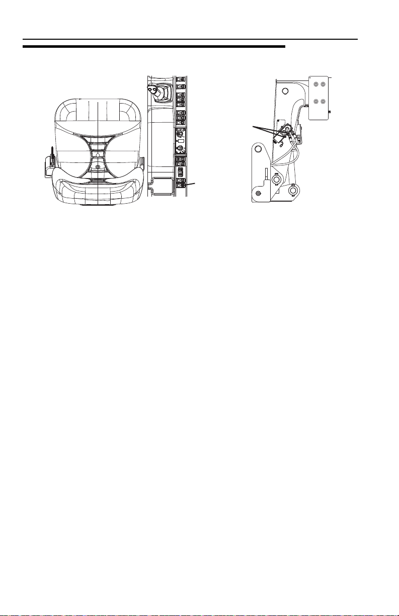
Section 5 - Attachments and Hitches
OAL1920
2
1
OAL2080
5.7 HYDRAULIC OPERATED ATTACHMENT
1. Install attachment (see page 5-9 or 5-12).
2. Press and hold auxiliary hydraulic pressure relief switch (1) for two seconds to
relieve pressure at both auxiliary fittings (2).
3. Perform “Shut-Down Procedure” on page 4-3.
4. Connect attachment hoses to both auxiliary fittings.
5-14 31200743

Section 5 - Attachments and Hitches
5.8 ADJUSTING/MOVING FORKS
Carriages may have different locations where forks can be positioned. Two different
methods can be used for repositioning, depending upon the carriage structure.
Note: Apply a light coating of appropriate lubricant to ease sliding of forks or fork
bar.
To slide forks:
1. Ensure attachment is properly installed. See “Attachment Installation” on
page 5-9 or “Universal Quick Attach (UQC)” on page 5-12.
2. Elevate attachment to approximately 5 ft (1,5 m) and tilt carriage forward until
fork heel is free from attachment.
3. Stand at the side of the carriage. To slide fork toward the center of the carriage,
push the fork near the fork eye. To slide fork toward the edge of the carriage,
pull the fork near the fork eye. To avoid pinching, do not place fingers or thumb
between the fork and carriage structure.
If removing fork bar is necessary:
1. Rest forks on ground.
2. Remove fork bar.
3. Reposition forks.
4. Reinstall the fork bar and fork bar retaining mechanism(s).
5-1531200743

Section 5 - Attachments and Hitches
5.9 ATTACHMENT OPERATION
• Capacities and range limits for the telehandler change depending on the
attachment in use.
• Separate attachment instructions must be kept in manual holder in cab with this
Operation & Safety Manual. An additional copy must be kept with the attachment
if it is equipped with a manual holder.
Note: Operations described within this section reference the Lift joystick pattern.
Refer to page 3-15 if using Loader joystick pattern.
NOTICE
EQUIPMENT DAMAGE. Some attachments may contact the front tires or
machine structure when the boom is retracted and the attachment is rotated.
Improper use of attachment may result in attachment or machine structural
damage.
NOTICE
EQUIPMENT DAMAGE. Avoid contact with any structure or object when lifting a
load. Maintain clearance around boom structure and load. Failure to maintain
clearance may result in attachment or machine structural damage.
5-16 31200743

Section 5 - Attachments and Hitches
This Page Intentionally Left Blank
5-1731200743
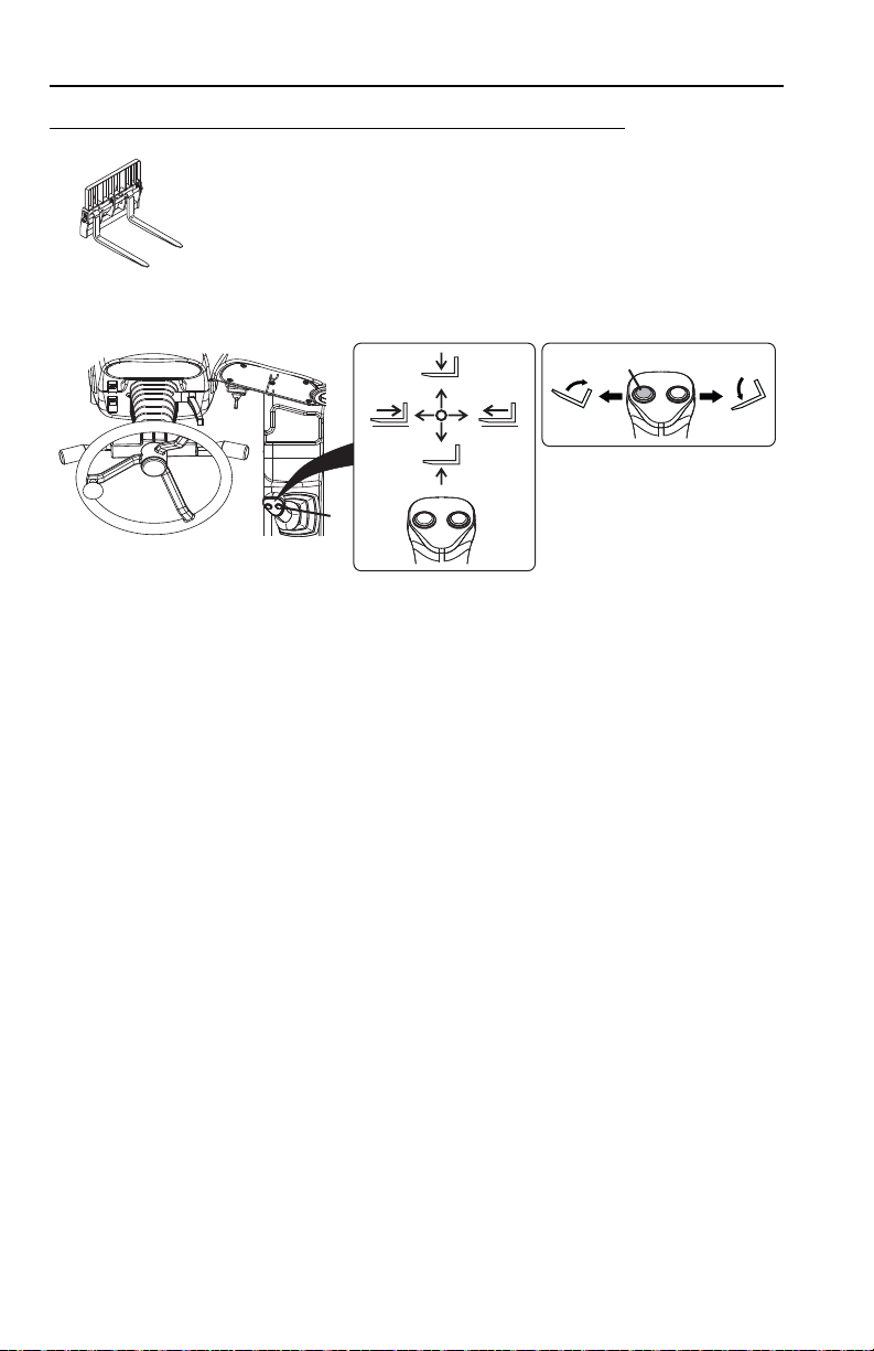
Section 5 - Attachments and Hitches
OY0690
OAL1601
1
2
Carriage with Forks
Use Carriage Attachment Capacity Chart
To determine maximum capacity, refer to “Telehandler/
Attachment/Fork Capacity” on page 5-4.
The joystick (1) controls lift/lower and the extend/retract movement of the boom.
The tilt button (2) enables fork tilt.
• While pressing and holding button move joystick left to tilt up.
• While pressing and holding button move joystick right to tilt down.
Installation Procedure:
• Refer to “Attachment Installation” on page 5-9.
Equipment Damage Precautions:
• Do not use forks as a lever to pry material. Excessive prying forces could
damage forks or machine structure.
• Do not attempt to lift loads that are attached or connected to another object.
5-18 31200743

Section 5 - Attachments and Hitches
OY0640
OAL1961
1
2
Fork Mounted Hook (ANSI & CE)
Use Appropriate Carriage Capacity Chart
To determine maximum capacity, refer to “Telehandler/
Attachment/Fork Capacity” on page 5-4.
Suspend loads in accordance with requirements set forth in Section
1 - General Safety Practices.
The joystick (1) controls lift/lower and the extend/retract movement of the boom.
The tilt button (2) enables fork mounted hook tilt.
• While pressing and holding button move joystick left to tilt up.
• While pressing and holding button move joystick right to tilt down.
Installation Procedure:
• Ensure carriage is properly installed. Refer to “Attachment Installation” on
page 5-9.
• Secure the fork mounted hook to the forks by sliding the fork mounted hook onto
the parent forks and install the retaining pin behind the vertical shank of the fork.
Operation:
• Pallet or lumber forks of an appropriate load rating must be used. Do not use with
cubing or block forks.
• Weight of fork mounted hook and rigging must be included as part of total load
being lifted.
• Do not use fork mounted hook with attachments capable of rotating (i.e. side tilt
and swing carriages) without disabling the rotation features.
5-1931200743

Section 5 - Attachments and Hitches
OAL1550
OAL1601
1
2
OAL1950
3
Side Tilt Carriage
Use Side Tilt Carriage Attachment Capacity Chart
To determine maximum capacity, refer to “Telehandler/
Attachment/Fork Capacity” on page 5-4.
The joystick (1) controls lift/lower and the extend/retract movement of the boom.
The tilt button (2) enables fork tilt.
• While pressing and holding button move joystick left to tilt up.
• While pressing and holding button move joystick right to tilt down.
To Side Tilt:
The auxiliary hydraulic button (3) enables carriage side tilt.
• While depressing button move joystick right to side tilt right.
• While depressing button move joystick left to side tilt left.
Installation Procedure:
• Refer to “Attachment Installation” on page 5-9.
5-20 31200743

Section 5 - Attachments and Hitches
WARNING
CRUSH HAZARD. Do not use side tilt to push or pull objects or load. Failure to
comply could cause object or load to fall.
Equipment Damage Precautions:
• Do not use forks as a lever to pry material. Excessive prying forces could
damage forks or machine structure.
• Do not attempt to lift loads that are attached or connected to another object.
5-2131200743

Section 5 - Attachments and Hitches
OAL1540
OAL1601
1
2
OAL2210
3
Side Shift Carriage
Use Side Shift Carriage Attachment Capacity Chart
To determine maximum capacity, refer to “Telehandler/
Attachment/Fork Capacity” on page 5-4.
The joystick (1) controls lift/lower and the extend/retract movement of the boom.
The tilt button (2) enables fork tilt.
• While pressing and holding button move joystick left to tilt up.
• While pressing and holding button move joystick right to tilt down.
To Side Shift:
The auxiliary hydraulic button (3) enables carriage side shift.
• While depressing button move joystick right to side shift right.
• While depressing button move joystick left to side shift left.
Installation Procedure:
• Refer to “Attachment Installation” on page 5-9.
5-22 31200743

Section 5 - Attachments and Hitches
WARNING
CRUSH HAZARD. Do not use side shift to push or pull objects or load. Failure to
comply could cause object or load to fall.
Equipment Damage Precautions:
• Do not use forks as a lever to pry material. Excessive prying forces could
damage forks or machine structure.
• Do not attempt to lift loads that are attached or connected to another object.
5-2331200743

Section 5 - Attachments and Hitches
OZ0730
OAL1611
1
2
Bucket
Use Appropriate Bucket Capacity Chart
To determine maximum capacity, refer to “Telehandler/
Attachment/Fork Capacity” on page 5-4.
The joystick (1) controls lift/lower and the extend/retract movement of the boom.
The tilt button (2) enables bucket tilt.
• While pressing and holding button move joystick left to tilt up.
• While pressing and holding button move joystick right to tilt down.
Installation Procedure:
• Refer to “Attachment Installation” on page 5-9.
Operation:
• Raise or lower boom to appropriate height for loading material from stockpile.
• Align telehandler with face of stockpile and drive slowly and smoothly into pile to
load bucket.
• Tilt bucket up far enough to retain load and back away from pile.
• Travel in accordance with requirements set forth in Section 1 - General Safety
Practices.
• Tilt bucket down to dump load.
5-24 31200743
 Loading...